Domain Engineering: A Conceptual Model of the
Software Application Architecture
Sanjay Bhagwan Sonar,
PhD
Associate Professor
Dept. of Computer Science and IT
Rai University, Ahmedabad
Gujarat, India
Vimal N. Pandya,
PhD
Director
Navgujarat College of Computer Applications
Gujarat University, Ahmedabad
Gujarat, India
ABSTRACT
Domain is the business functional workout area to be designed in the mode of discrete component, domain workout area is a conceptual representation of the business logic and rules and real situation objects in the domain, here domain is also called conceptual model of the requirement engineering. In software development requirements must start with domain modeling and business workout area is formulated by the domain modeling for software application architecture. Before requirements can be defined the application domain must be defined. Here domain is the initial conceptual model of the requirement engineering. Domain classify with vertical and horizontal method to prove number of modules in hierarchical mechanism with interface in vertical method and functionalities of the each modules is defined in horizontal method. Domain engineering directly support to the acquiring business rule, logic and functionalities. As well as define the requirement elicitation and specification using tools and techniques of the domain engineering. Using this the physical objectization is extracted. In this paper we outline the basic facets of objectization from domains.
General Terms
Domain work out area, Clustering of base domain for discrete work, define functionality of each domain by business logic
Keywords
Domain, Sub-Domain, Co-Domain, Ethnography, Heuristics, Brainstorming, Composition, Segmentation, Objectization.
1.
INTRODUCTION
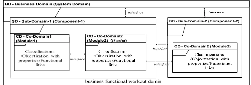
[image:1.612.98.513.492.633.2]In real situation, the present businesses terms are based on the discrete component mode, based on business rule and logic divided into discrete component as the bases on the interfacing topologies also these components are divided into modules/ functionalities as the bases of the requirements of the business logic[2] Here business workout area of the domain engineering is represented by visual representation which encompasses classes or real situation objects in the domain. The domain model representations the hierarchy of the sub-domain and co-domain is called vertical representation of the domains, where classifications, functionalities, attributions, interfaces and binding of the domains is called horizontal domain according to the business functionalities [1],[11] Here, We have designed the business domain as the business functional workout area and Sub-domains are the discrete component of the business as well as component is divided into co-domain (modules), and all functionality are carried out by the almost in co-domain. At last the base domain is clustered for sub-domain to define discrete work out segments in base domain in as a vertical form, and each sub-domain horizontally bifurcated for define functionalties to identify actual objectization[13].
Fig. 1 Conceptual Domain models
The above figure 1 denote the domains system in the business model, as like BD- business domain is the main system domain which cover all business functional workout area. The functional world view of the business and BD has discrete sub-domain and each sub-domain has discrete co-domain.
This partition of the domain decomposition is based on the functional dependency as the requirements of the business.
Here Base Domain (BD), Sub-Domain (SD) and Co-Domain (CD)
SD = {CD1, CD2, CD3 ….,CDn}, CD ح SD
Here BD contains more than one SDs and SD contains more than one CDs, here SD is subset of BD and CD is subset of SD.
2.
OBJECTIVES
The Domain modeling is the prerequisite task of the requirement engineering, according to the domain model, we can define the actual functional requirements of the business. Therefore domain engineering is the subset of the requirement engineering. The following objectives are measured for proceed the system from domain engineering to objectization.
1.
Design Base domain of the system2.
Identification the sub-domain and co-domain from thebase domain according to business logic/functionalities
3.
Design interface oriented architecture of the eachdomain for identification of discrete component and module
4.
Functionalities of the each co-domain5.
Pre requisite of the requirement engineering6.
Definition of the requirement elicitation7.
Graphical representation of the domains8.
Genericity in all domain objects for commonness.3.
EXPERIMENTAL DESIGN AND
PROCEDURE
Here we design the procedure of the domain engineering process from business work-out area to domain interfacing as the basis of business functional requirements. The domain decomposition is segmented in vertical and horizontal mechanism of the sub-domain and co-domain.
3.1
Vertical mechanism of the domain
The vertical decomposition of the domain is segmented in hierarchical form of the sub-domain and co-domain according the business logic. The following procedural task denote vertical domain system3.1.1 Identify Business rule/logic workout domain
3.1.2 Identity/Define domain Decomposition (sub-domains/Components)
3.1.3
Design
sub/Co-domain
Interface/Composition
3.1.1 Identify Business rule/logic workout
domain
Business functional logic is a formal condition and Model of real business objects of business rule that describes a specific procedure. The rules are workflow includes tasks, procedural steps, input and output information tools, definitions and constraints that apply to an organization. Domain logic is the initial task of the software applications architecture, and identification of the software modules and objectization in each module. Also prescribes how business objects interact with one another, and implements the routes and the methods by which business objects are accessed and updated. Business
logic determines how this rule is implemented as a process,
like the application of Interest rate on fix-deposit is a business rule but the calculations [8],[15],[18].
The business rules for ATM transaction is as like,
1. The Customer having the particular bank debit card.
2. Customer is getting its PIN by SMS by its enrolled mobile number from the bank.
3. Each Customer transaction must be atomic
The business logic for ATM transaction is as like,
1. Verify the card and PIN of the customer as authorized customer.
2. Verify the account Number of the customer validation.
3. Verify the required Balance of the customer in account for withdrawal.
4. Verify the minimum balance of the customer in particular account.
5. Generate appropriate message for the customer.
6. Update the withdrawal amount from the account if balance is sufficient.
7. Update the log file.
8. Update the transaction file of the bank.
9. ATM-machine Count the notes.
10. Issues the amount to the customer by the machine for allocated time period.
11. Generate the withdrawal slip for the customer if wanted by the customer.
12. Consistent state
3.1.1.1
The
domain
extracts
tools
and
techniques.
1. Ethnography (observation technique to understand
operational processes)
2. Heuristics (Artificial logic applied also backward
and forward passes are applied)
3. Workshops (Collaborations of the stack holders,
JAD (Joint Application Developers/Members)
4. Brainstorming (Dynamic/Creative ideas for the
solution, made conclusion for problem)
5. Prototyping (Applied systems development method
for the solutions of problems)
6. Interview and questionnaires (asking questions
related to the domain work out area)
7. Survey and document review (Observation and
documents verification as manual)
8. Group center (JAD members (clients, users and
developers) center points) [1],[15],[19].
3.1.1.2 Additional tasks for extraction mining
tools and techniques
.
It can be useful to attach to a mined rule additional informational and workflow attributes, such as: [1],[15].
1. Reviewer text annotations
2. Rule type (I/O, calculation, validation, security)
4. Workflow status (extracted, working, accepted, rejected)
5. Transition (valid, requires modification, duplicate, complete)
6. Transition (valid, requires modification, duplicate, complete)
7. Transition (valid, requires modification, duplicate, complete)
8. Reviewer Identity
9. Program derived from
10. Code segment location (start, end)
11. Code segment text
12. Input and output data elements
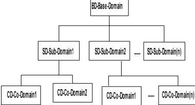
3.1.1.3. Vertical Domain Approach:
Top-Down
Hare different types of approaches have the sense for designing the domain models from its own characteristics. Here the Top-down approach is suitable for designing the vertical domain. Top down approach is the hierarchical approach of the domain decomposition, like following figure 2[8],[10]
[image:3.612.92.524.68.715.2]Fig. 2 Vertical approach of the domain
decomposition
3.1.2
Identitification / Define domain
Decomposition (sub-domains)
[image:3.612.329.529.158.318.2]The following figure 3 presentation the conceptual decomposition of the base domain into sub-domain as a segmentation, this segmentation is find out by the above domain extraction tools and techniques. Also implies mining tools for designing the sub-domain and interface with cardinality between the sub-domains.
Fig. 3 Sub-domain conceptual representation
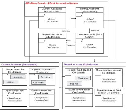
The following figure 4 represents practical example of the sub-domain decomposition The following figure 4 represents practical example of the sub-domain decomposition of the bank accounting system, here bank have different
types of atomic accounts and each account is maintained separately [2]
[image:3.612.91.281.355.458.2] [image:3.612.105.510.504.704.2]In the above figure 4 there are four different account designed as sub-domain of the system. And also two co-domains defined in the sub-domain current account and loan account. Here each sub-domain is interacted with other sub or co-domain in the boundary of the base co-domain. Each sub co-domain separately interacted with other sub or co-domain based on the business functional requirements. The identification of the sub-domain is based on the functional requirements to be discrete work-out area of the system. The functional dependency between sub-domain to sub-domain or to co-domain is designed by the business logic of the system. The business rule and logic would be the central point in functional dependency to decompose the base domain into sub-domain vertically. Here the cardinality of interface between the domains is also depended on the functional dependency to applying the business requirements of the system.
3.1.3 Define sub-domain/co-domain
interfaces
Domain interfaces in between sub-domain to sub-domain and co-domain interaction purely basis on the functional dependency in business logic of the requirements of system. Interface is required for the information inserting, deleting, displaying, printing, viewing, verifying, transferring, modifying, accessing, etc. For this task, the sub-domain interacts with other one or more than one Sub or Co-domain as business rule/logic. The following figure 5 denotes the interfaces from sub-domains. By the business requirements, the functional dependency of the interface is that, all fixed deposit customers only can get overdraft and loan from the bank, as same, all saving account customers only can take loan from the bank. According to the business logic, system indentifies customer status of the deposit and saving account before issuing the loan and overdraft therefore previously conceptual interface will be as below.
Fig.5 Sub-Domain & co-domain interface
The above figure 5 denotes interface between sub-domains is conceptual model, according to the business logic, and each sub-domain interact with other atomic sub-domain or also interact with co-domain.3.2
Horizontal mechanism of the
domain
3.
2.1
Identify/Define
Co-Domain
from
decomposed Sub-domains.
Fig. 6 Co-Domain representations from decomposed sub-domain
Each sub-domain has individual co-domains like current account co-domain is Ultima current account, Supreme current account, Premium current account, Apex current account, and Regular current account and Flexi current account. As same deposit sub-domain co-domain like Regular fixed deposit, Recurring fixed deposit, Super Saver Facility etc.
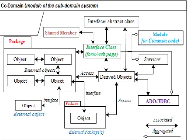
3.2.2 Define conceptual functionality of the
co-domain.
The following figure 7 denotes conceptual classes and packages for the co-domain current account, to covers physical functionalities of the co-domain. Here if co-domain does not exist? Then all functionalities are covered in the sub-domain in the system. The basic functionalities are defined in
the sub/co-domain by packages, abstract class, derived class, interface class, shared members, module class, external class interaction with internal class, and JDBC for database connection class etc, This functions are associated and aggregated with each other as the basis of business logic with high cohesion and low coupling. Functionality should nearly loosely couple as based on the high cohesion and low coupling. The conceptual classes’ terms are designed by [2],[8]
1. Symbol: words or images or actors are representations
are conceptual classes.
2. Intension: The definition of the conceptual classes.
Fig. 7 Conceptual Classes of the Sub / Co-domain
3.3
Requirement Mining
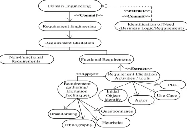
Here identification of needs are extracted from the domain engineering, and functional requirements are elicited using requirements elicitation tools and requirements gathering techniques support to identify actor, use cases, initial objects and PDL for define functional requirements of the system, as prescribed business model. The following tasks are carried out by the requirement engineering
1.
Requirement Elicitation2.
Requirement Specification3.
Requirement Validation3.3.1
Requirement Elicitation
Fig. 8 Requirement Elicitation Process
In above figure 8 denote the JAD members use the above requirement elicitation tools for identifies actual functionalities from the each co-domain or sub-domain according to requirement elicitation techniques. Here requirement elicitation tools that realize for the functional requirements of the system. The following requirements elicitation activities/tools described to extracts the functional requirements of the system. The objectization is defined and designed from the requirement elicitation tools [8],[12]
•
Identify initial objects
Identify initial objects, apply the following heuristics,
1. Recurring noun from the use cases
2. Define actors which are interact with other actor(s) 3. Identify cases which are operated by the actor(s) 4. Identify interface/form/module which is interact
with other object/actor 5. Identify Data sources and sink
6. Identify user interaction task like master form/home page/MDI form/form
•
Identify actors
Identify actors from the use case model, apply the
following heuristics,
1. Identify tangible entities from the task
2. Extract tangible entities from the use case realization
3. Identify use case interaction entities. 4. Identified transitions occurred by the actor 5. Identify the entities specialization or generalization 6. Identify interface/ boundary objects which are
interact with tangible entity(s)
7. Identify control or link objects from the use case synchronization/ automation
•
Identify use cases (carried out by an
actor(s))
Identify use cases, apply the following heuristics,
1. Identify transition/ interaction from one entity to other entity
2. Identify internal and external interface of the objects/entities
3. Identify operation/functionality between objects/entities
4. Design scenario for the objects transition, to Identify cases
5. Identify synchronization/ automation/threads from the operation
6. Identify the interface classes/objects to be operated by other entities
•
Define PDL (Programmable
Development Language)
3.3.2
Requirement Specification and Validation
Fig. 9 Requirement Elicitation Process
The requirements are specified by the JAD members (customer, users, and developers) of the system from the each co-domain, JAD members jointly design the requirements specifications of the system. Especially requirements elicitation tools designed graphically for the requirement specification, as well as use case scenarios are also designed for the specifications [1],[8]
3.3.3
Requirement Validation
After the requirements elicitation and specification, the requirements are validated by the JAD members using the following task checking for the accurate functional requirements of the business model. The following tasks are to be carried out for the requirements validation as the functional requirements of the system.
1. Basic source/sink are covered
2. Verify business logic
3. Maintain actor interaction
4. Maintain system interaction
5. Define interaction design
6. Define actors which are converter in to the database
7. Accuracy in automated and synchronized operations
8. Validity check, Consistency check, Completeness check And realism check
9. Applied task as like Review, Prototyping, Automated consistency Analysis And Test case generation for actualization
4. CONCLUSION
Here present businesses term is based on the discrete component mode, that directly support to the present pure object oriented programming languages, here domain model and requirement model support them. The domain engineering decomposes the system into different sub-domain as vertical hierarchical form according the business requirements. Same horizontal domain designs the conceptual model of the functionalities of the each co-domain. After the both domain is identified, the requirements is mined for actual objectization according to business goal/logic using different task of the domain engineering and requirement engineering. Here requirement elicitation is enquired by above task of the domain specifications. The domain engineering directly support to the JAD member for identification and definition of the requirements engineering and achieve the application requirements of the business.
5. ACKNOWLEDGMENTS
6. REFERENCES
[1] Bernd Bruegge, Allen H. Dutoit. “Object Oriented Software Engineering, Using UML, Patterns, and Java”, Second Edition, Pearson Education, 2010
[2] Craig Larman. “Applying UML and Patterns”, 3rd Addition, Pearson Education Inc 2005
[3] Civello F, “Roles for composite Objects in Object Oriented Analysis and Design”, OOPSLA, ACM SIGSOFT Vol. 28 No. 10, pp 376-393
[4] Desmond Francis D’ Souza and Alan Cameron Wills, “Objects, Components, and Framework with UML”, 2nd Addition, Addition-Wesley Object Technology Series 1999
[5] G. Kotonya and I. Somerville, “Requirements Engineering”, Processes and Techniques, John Wiley Sons
[6] Geri Schneider, Jason P. Winters. “Applying Use Cases”, 2nd Addition, Addition-Wesley Object Technology Series 1998
[7] Grady Booch. “Object Solutions”, 2nd Addition, Addition-Wesley Object Technology Series 1996
[8] Ian Somerville, “Software Engineering”, 6th Edition, Pearson Education, 2005
[9] Juhani Livari, “Object Oriented as Structural, Functional and behavioral Modeling”: A comparison of six methods for Object Oriented Analysis, Department of Computer Science and Information science, University of Jyvdskyla
[10]Jim Arlow, Ila Neustadt. “UML and the Unified Process”, 2nd Addition, Addition-Wesley, Object Technology Series, 2002
[11]M. Mattsson and J Bosch “Object oriented frameworks”
Composition problems, causes and solutions In Building Application Frameworks: Object-Oriented Foundations
of Framework Design, pp. 467-487, M. Fayad, D. Schmidt, R. Johnson editors, Wiley Press, 2000
[12]M. Davis, “Software Requirements”: Objects, Functions, & States, Prentice Hall, Englewood Cliffs, 1993
[13]Meyer B., “Applying Design by Contract”, IEEE Computer, Oct 1992
[14]N. Bouassida, H. Ben-Abdallah, and F. Gargouri, A. Ben-Hamadou:” A stepwise Framework Design Process”, IEEE International Conference on Systems Man and Cybernetics, 07-09 October, Hammamet, Tunisia, 2002
[15]P. Loucopoulos and V. Karakostas, “System Requirements Engineering”, McGraw-Hill 3rd Addition 2007
[16]R. H Thayer and M Dortman “System and Software Requirements Engineering”, Tutorial, IEEE Computer Society Press
[17]Yun-Tung Lau, “The Art of Objects” Object-oriented Design and Architecture, Addison-Wesley object technology series, Addison-Wesley, 2001
[18]Wirfs - Brock, R. and Wilkerson, B. “Object Oriented Design” A Responsibility- Driven Approach. In Proceedings of OOPSLA '89 Conference, SIGPLAN Not (ACM) 24, 10, (New Orleans, Louisiana, October 1989), pages 71-76
[19]R. H Thayer and M Dortman “System and Software Requirements Engineering”, Tutorial, IEEE Computer Society Press