ISSN Online: 2327-6053 ISSN Print: 2327-6045
DOI: 10.4236/msce.2018.64006 Apr. 12, 2018 39 Journal of Materials Science and Chemical Engineering
Simulation of Particle Agglomeration in
Turbulent Flow
Peiling Yan, Deshuai Sun
*, Yang Yu, Xiankun Shen, Yanfei Qi
College of Chemical Engineering, Qingdao University, Qingdao, China
Abstract
Turbulence agglomeration is an effective way to promote agglomeration of particles. The coupling of classic Eulerian-Eulerian two-fluid model with pop-ulation balance model was used to simulate the agglomeration process. The simulation results show that turbulence agglomeration could reduce 56% of emission of fine particles less than 10 μm. Smallest particles less than 2 μm were easily be removed, while the removal values of particles with medium size was very low. The suitable spacing of vanes was benefit to remove the fine particles from gas flow. Small angle of the vanes could improve the removal of fine particles.
Keywords
Fine Particles, Turbulence, Vane Spacing, Vane Angle
1. Introduction
In recent years, the prevention and controlling of fine particle pollutant have become the focus of the whole society. Due to the larger surface area of fine par-ticles, they are easy to enrich the toxic heavy metals, acidic oxides, organic pol-lutants, bacteria and viruses in air. When they enter into the body by respiration, they can deposit in the lungs, and therefore harm seriously the cardiovascular system [1] [2].
The fine particles in air are mainly from the combustion of fossil fuels. They are difficult to be removed completely by conventional dust collector because of the small size [3]. Particle agglomeration technology is a potential method to improve the removal efficiency of fine particles using the conventional dust col-lector. Several external fields and some chemical agents were applied to make fine particles to “grow” into large particles agglomeration which can be filtered easily. The agglomeration methods mainly include acoustic agglomeration, How to cite this paper: Yan, P.L., Sun,
D.S., Yu, Y., Shen, X.K. and Qi, Y.F. (2018) Simulation of Particle Agglomeration in Turbulent Flow. Journal of Materials Science and Chemical Engineering, 6, 39-46. https://doi.org/10.4236/msce.2018.64006
DOI: 10.4236/msce.2018.64006 40 Journal of Materials Science and Chemical Engineering chemical agglomeration, heat agglomeration, turbulence agglomeration, electric agglomeration, vapor phase change agglomeration and etc.
Turbulence agglomeration technology is wildly used in industry. The velocity gradient in flow can energy to promote the collision and agglomeration of fine particles with larger particles, which is a simple and low cost technology. At present, many scholars have carried out extensive experimental and theoretical research on turbulence technology. The agglomeration experiment of fly ash particles in turbulent flow introducing by gas jet found that increasing Reynolds number and velocity of the jet in the main air flow could improve the efficiency of particle removal [4]. And the removal efficiency of particle less than 1 μm is very high [4]. Fluent is a commercial CFD package widely used in the simulation of gas solid two phase flow. The results from simulation using CFD software in-dicated the increasing gas velocity could enhance the effect of turbulence on the particles and increase the collision probability in a turbulence condensers com-posed of Z-type turbulent vanes [5]. Zhang et al. changed the configuration of the turbulent element and found these elements should not be arranged too densely or too distantly [6].
Gas jet was introduced into the agglomeration room to form a local turbu-lence to help particle agglomeration [7] [8]. In order to strengthen the effect of turbulence, one vanes assembly were provided along the overall direction of flow. The aim of this paper was to investigate the effect of vane on fine particle agglomeration in turbulent flow using the numerical simulation method.
2. Mathematical Model
2.1. The 2D Model of Fine Particles Agglomeration Chamber
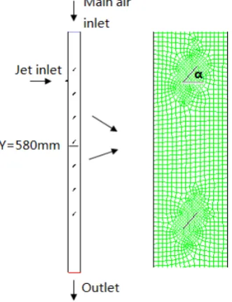
To obtain the effect of the gas jet on the fine particle agglomeration, an experi-ment-scale agglomeration chamber was setup according to our previous work [9]. The agglomeration chamber was a round, transparent pipe with an inner diameter of 50 mm and a length of 1000 mm. The two ends of the tube were sealed by plates. The vain assembly was fixed inside the chamber. The size of the vane is 15 × 15 mm, and the distance of vane was 100 mm. A round, jet nozzle, with an inner diameter of 2.0 mm, was located in the chamber wall at 150 mm below the main inlet nozzle. In simulation process, a 2D model was selected.The physical model of the agglomeration chamber was meshed by unstruc-tured grid in Fluent 15.0 pre-processing software Gambit, and the grid indepen-dence was verified. It was found that increasing the number of grids had little effect on the flow field in the agglomeration chamber. Therefore, the grids (68180) and the mesh sizes were considered to meet the requirements of the calculation accuracy. Figure 1 illustrated the chamber configuration and the CFD grid of partial enlargement.
2.2. Two-Phase Fluid Model
DOI: 10.4236/msce.2018.64006 41 Journal of Materials Science and Chemical Engineering
Figure 1. Agglomeration chamber structure diagram and local grid diagram.
interpenetrating into and interacting with each other in the whole domain under consideration [10]. Momentum and continuity equations were solved for each phase. Due to the low centration of fine particles, standard k-ε model was se-lected to calculate two-phase flow [11].
2.3. Population Balance Model
In order to improve the accuracy, this paper introduces the population balance model based on Euler two fluid model (PBM), to calculate the particle move-ment and the distribution of polydisperse particles [12]. Therefore the popula-tion balance concept is a well-established method to calculate the size distribu-tion of the dispersed phase. In the process of turbulence agglomeradistribu-tion, PBM is used to describe the variation of particles numbers, which assumes that the new agglomerations generate after the collision between particles. The PBM equation can be expressed as follow.
0 0
[image:3.595.293.459.77.293.2]1
[ ( , )] ( ', ') ( ', ) ( ', ) ' ( , ') ( , ) ( ', ) ' 2
v
n v t v v v n v v t n v t dv v v n v t n v t dv
t α α
∞
∂
= − − −
∂
∫
∫
(1)where ∂[ ( , )]n v t is the number concentration in the volume interval v to v+dv at time t. a v v( , ') is the aggregation kernel between two particle with
volumes of v and v'. n v t( , ) is the size distribution function. The PBM
equa-tion is an integral equaequa-tion solved by the means of discrete method in this paper [13].
2.4. Turbulent Aggregation Kernel
iner-DOI: 10.4236/msce.2018.64006 42 Journal of Materials Science and Chemical Engineering tial particles (St~0), finite inertial particles and great inertial particles (St~∞).
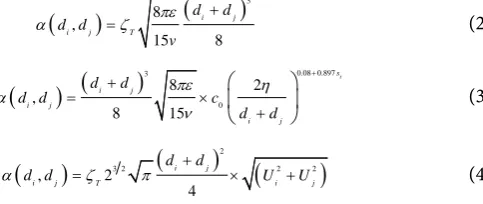
These particles were influenced by different flow forces, which results in the dif-ferent turbulent aggregation kernel as Equation (2) to Equation (4).
(
)
(
)
3 8 , 15 8 i ji j T
d d d d
v
πε
α =ζ + (2)
(
) (
)
0.08 0.897 3 0 8 2 , 8 15 t s i j i j i j d dd d c
d d πε η α ν + + = × +
(3)
(
)
3 2(
)
2(
2 2)
, 2
4
i j
i j T i j
d d
d d U U
α =ζ π + × + (4)
where di, dj is the diameter of particle i and j, respectively. ζT is a pre-factor
that takes into account the capture efficiency coefficient of turbulent collision. εis the shear rate. η was turbulence length scale. Uiis the mean squared velocity
for particle i [14].
2.5. Simulation Conditions
The aerosol inlet boundary is velocity condition inlet, in which the velocity of main gas was 0.8 m/s. And the outlet boundary was pressure condition. The par-ticle density was 1838 kg/m3, and the initial particle fraction was 0.03%. The
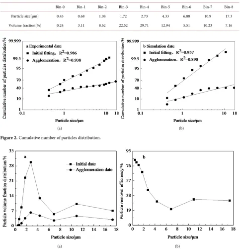
ve-locity of gas jet was 22 m/s. The simulation solution was solved using Phase Coupled SIMPLE. The initial particle size was in range of 0.43 - 17 μm, which was divided into nine intervals, as shown in Table 1.
3. Results and Discussions
3.1. Effect of Turbulent Agglomeration
[image:4.595.292.534.126.228.2]When the gas containing fine particles flowed across the vanes, the small scale turbulence around the vane entrained the smaller particles, and then increased the retention time. Therefore, they could be captured easily by larger particles, resulting inthe decrement of the number of fine particle. Figure 2 described the cumulative number distribution of the particles. From Figure 2(a), it was found 88% of particles was less than 2 μm (PM2) for the initial distribution, although the mass of these particles was very small. After agglomeration of particles, the number of these smaller particles decreased to 45%. For particles with the di-ameter less than 10 μm (PM10), agglomeration could reduce 41% of emission [9]. Figure 2(b) showed the simulation results, and suggested the percent of PM10 decreased about 56%. The simulated data were slightly higher than the experimental value.
DOI: 10.4236/msce.2018.64006 43 Journal of Materials Science and Chemical Engineering
Table 1. Initial particle diameter distribution.
Bin-0 Bin-1 Bin-2 Bin-3 Bin-4 Bin-5 Bin-6 Bin-7 Bin-8
Particle size[μm] 0.43 0.68 1.08 1.72 2.73 4.33 6.88 10.9 17.3
Volume fraction[%] 0.24 3.11 8.62 22.52 29.71 12.94 5.51 10.23 7.16
[image:5.595.56.540.85.588.2](a) (b)
Figure 2. Cumulative number of particles distribution.
[image:5.595.62.533.359.586.2](a) (b)
Figure 3. Effect of oblique vane on particle agglomeration.
DOI: 10.4236/msce.2018.64006 44 Journal of Materials Science and Chemical Engineering
[image:6.595.257.492.293.476.2]Figure 4. Effect of vane interval on particle removal efficiency.
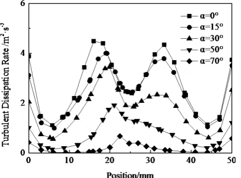
Figure 5. Effect of vane angle on particleremoval efficiency dis-sipation rate.
[image:6.595.255.498.529.708.2]DOI: 10.4236/msce.2018.64006 45 Journal of Materials Science and Chemical Engineering
3.2. Effect of Vanespacing on Particle Agglomeration
The spacing of vanes could affect the vortex of the turbulent flow. Figure 4 gave the effect of vane spacing on the number removal efficiency. When the spacing of vanes was 50 mm and 100 mm, the removal efficiency of particles with all size were up to the best values. Subsequently, the removal value decreased with the increment of the spacing of vane. The suitable spacing of vanes was benefit to form the contiguous vortex of the turbulent flow, which could entrain conti-nuously the small particles. The excessive spacing could harm the continuity of the structure of vortex, which decreased the agglomeration of particles in turbu-lent flow [6].
3.3. Effect of Vane Angle on Particle Agglomeration
Figure 5 showed the effect of vane angles on the removal efficiency of particle. The removal efficiency of the particles decreased with increasing the angle of vanes. For the lowest efficiency at 7 μm, the values decreased from 32% to 13%. This indicated the vane angle affected obviously the strength of turbulent flow, as shown in Figure 6.
Figure 6 revealed the turbulence dissipationrate at the cross section of Y = 580 mm. It can be seen the turbulence dissipation rate decreased with the incre-ment of the vane angles. There were two maximum peaks when the vane angles was in range of 0˚ - 30˚, suggesting the best entrainment of fine particles. Therefore, the higher removal efficiency could be observed. This result was con-sistent with the reports of Zhang et al. [6].
4. Conclusions
1) For fine particles from fly ash, 88% of particles was less than 2 μm accord-ing to the cumulative number distribution. Turbulence could encourage the ag-glomeration of fine particles. After agag-glomeration of particles, the number con-centration of PM 10 could reduce 41% of emission according to experimental data. The simulation data indicated the percent of PM 10 decreased about 56%. Smallest particles less than 2 μm were easily be removed, while the removal val-ues of particles with medium size was very low.
2) The suitable spacing of vanes was benefit to remove the fine particles from gas flow. When the spacing of vanes was 50 mm and 100 mm, the removal effi-ciency of particles with all size were up to the maximum values. Small angle of the vanes could improve the removal of fine particles.
Acknowledgements
DOI: 10.4236/msce.2018.64006 46 Journal of Materials Science and Chemical Engineering
References
[1] Yuan, Z.L., Li, W.L., Wei, X., Fan, F.X. and Shen, X.L. (2005) Study of the Sound Wave Effect on the PM2.5 Suspended in the Air by Numerical Method. Proceedings of the CSEE, 25, 121-125.
[2] Chen, D.L., Wu, K. and Mi, J.C. (2016) Experimental Investigation of Aerodynamic Agglomeration of Fine Ash Particles from a 330 MW PC-Fired Boiler. Fuel, 165, 86-93. https://doi.org/10.1016/j.fuel.2015.10.036
[3] Sun, D.S., Fang, L. and Liu, Y.L. (2014) Influence of Surfactant Sparys on Agglome-ration of Inhalable Particle. Adv. Mater. Res, 1044-1045, 344-347.
[4] Sun, D.S. and Guo, Q.J. (2010) Effect of Gas Jet on Agglomeration of Inhalable Par-ticles. Int. J. Chem. Reactor Eng, 8, 47-54. https://doi.org/10.2202/1542-6580.1961
[5] Liu, Z., Liu, H.X., Feng, X.X., Zhang, W.F., Li, H.L. and Xing, Z.Z. (2012) Simula-tion for the Flow Field of the Turbulence Coalescence Device and the Trajectory of Particles. Proceeding of the CSEE, 32, 71-75.
[6] Zhang, P.F., Mei, J.C. and Pan, Z.M. (2016) Influences of Elemental Arrangement and Particle Concentration on Fine Particle Amalgamation. Proceeding of the CSEE, 36, 1625-1632.
[7] Qin, T.T., Sun, D.S. and Liu, Y.L. (2015) Numerical Simulation into Agglomeration Process of Inhalable Particle in Double Gas-Jets. International Conference on Ma-terial, Mechanical and Manufacturing Engineering, 24, E114-E114.
https://doi.org/10.2991/ic3me-15.2015.51
[8] Yang, Z.N. and Guo, Q.J. (2011) Agglomeration of Coal Combustion Fly Ash In-halable Particles in Presence of Gas-Solid Jet Flow. J. Chem. Eng. Chin. Univ, 25, 225-230.
[9] Yu, Y., Sun, D.S., Yan, P.L. and Shen, X.K. (2017) Removal of Fine Particles with the Coupling of Turbulent and Chemical Agglomeration. Chin. J. Environ. Eng, 11, 209-215.
[10]Ishii, M. (1975) Thermo-Fluid Dynamic Theory of Two-Phase flow. Eyrolles, Paris. [11]Wang, F. and Mao, Z. (2005) Numerical and Experimental Investigation of
Liq-uid-Liquid Two-Phase Flow in Stirred Tanks. J. Ind. Eng. Chem. Res, 44, 5776-5787.
https://doi.org/10.1021/ie049001g
[12]Qian, J.H., Yang, M.G., Cao, Y.S., Gao, B. and Wang, H.Y. (2014) CFD-PBM Coupled Calculation on Liquid Solid Two Phase Flow Field in a Vortex Pump. Fluid Mach, 4, 23-27.
[13]Zhao, H.B., Zheng, C.G., Liu, Z.H. and Chen, Y.M. (2003) Microscalehydromechan-ical Model of Particulate Matter Originating from Coal-Combustion-Boiler. J. Hua-zhong Univ. of sci. & Tech. (Nature Science Edition), 31, 72-75.