State Based Static and Dynamic Formal Analysis of UML
State Diagrams
Fahad Alhumaidan
Department of Computer Science, College of Computer Sciences and Information Technology, King Faisal University, Hofuf, KSA. Email: [email protected]
Received March 28th, 2012; revised April 25th, 2012; accepted May 11th, 2012
ABSTRACT
Design and specification is a serious issue in software engineering because of the semantics involved in transforming the real world problems to computer software systems. Unified Modeling Language (UML) has been accepted as a de facto standard for design and specification of object oriented systems. Unfortunately, UML structures lack defining se- mantics of a system. Formal methods are proved powerful, particularly, at requirement specification and design level. For a moment, formal methods are not welcomed because of much use of mathematics in formal languages. Therefore, a linkage between UML and formal methods is required to overcome the above deficiencies. In this paper, a new ap- proach is developed by integrating UML and Z specification focusing on state diagram considering both the syntax and semantics. It is believed that this new approach will be effective and useful both at academics and industrial level. The resultant formal models of the approach are analyzed and validated using Z/Eves tool.
Keywords: UML; State Diagram; Formal Methods; Z Notation; Validation and Verification
1. Introduction
In software engineering, requirements analysis and design specification is a challenging task because transformation of real world issues to verifiable computer models has made it a really hard problem. Formal description of sys- tem’s requirements plays a vital role at initial phases of software engineering. Formal specification is the mathe- matical description of a system that may be used to con- struct the consistent system in a systematic and unambi- guous way. If we are able to describe formal specification of a system then it can easily be proved and demonstrated the correctness of the required system using computer verification tools. Formal description of a system has obvious advantages over the existing traditional ap- proaches, for example, an incorrect and inconsistent de- sign can be changed and modified before its implementa- tion reducing the software construction cost. Formal methods, based on discrete mathematics such as logic, set theory or graphs, are mathematical techniques used to describe formal description ensuring quality of software systems. But formal methods are not as used at industrial level as their benefits are observed. This is because, for a moment, the software industry people do not have much mathematical background as required in real software engineering.
The Unified Modeling Language (UML) is a standard
set of notations and diagrams for specifying, visualizing and constructing artifacts of software systems as well as for business modeling and other non-software systems [1]. UML is a multi-lingual graph based de facto standard used for design and development of object oriented (OO) sys- tems, despite the fact that its semantics is still semi-formal and allows ambiguities in design of a system [2]. Fol- lowing are few major issues in modeling using UML diagrams being hybrid and visual language:
UML structures are based on graphical notations and are prone to causing errors.
The hidden semantics of UML allow ambiguities at the design level of computer software systems.
The same system needed to be developed can be de- scribed by multiple notations or diagrams which may cause inconsistency or ambiguity in design of it. UML model may have multiple interpretations that
means, the recipient of the design may not find what the author(s) has put in the diagrams.
lizing UML diagrams to get full benefit at design level capturing complete functionality of the system to be de- veloped. This integration of formal notations and UML diagrams will result an approach for complete, consistent and correct modeling of a system. Z notation is a formal language, having computer tool support, used to describe and analyze the systems increasing confidence at an ab- stract level of specification. In this paper, state diagram is transformed to Z specification following syntax and se- mantics rules for modeling of statics and dynamics of a system. This work is part of our ongoing project on inte- gration UML and formal methods [5]. There exists a few work formalizing UML and formal methods presented in the next section in which mostly it is focused on syntax of the diagrams. In our work, instead of defining only syn- tactical mapping between UML and Z we have proposed and developed a conceptual model by capturing its se- mantics hidden under the diagrams. The major objectives of this research are:
Identifying and proposing an integration of UML and formal approaches to be useful in modeling of com- plex software systems
Investigating and providing syntactical and seman- tics-based relationships between most commonly used UML diagrams and Z notation
Analyzing and proving correctness of the proposed integration of above approaches
Developing an approach to provide an automated tool support to transform the UML abstract models to Z specification
For rest of the paper: In Section 2, related work is dis- cussed. Approach used is presented in Section 3. Integra- tion of state diagram and Z notation is given in Section 4. Finally conclusion and future work are discussed in Sec- tion 5.
2. Related Work
Although there exits a lot of work [6-10] on integration of approaches but there does not exists much work on linking UML diagrams with formal approaches. This is because the hidden semantics under the UML diagrams cannot be transformed easily into formal notations. It is mentioned that only closely related work is discussed in this section. For example, [11] have developed Alloy Constraint Ana- lyzer tool supporting the description of a system whose state space involves relational structures which are com- plex in nature. By the tool it is possible to analyze and develop a model by investigating the consequences of given constraints by an incremental approach. An ap- proach is demonstrated using XML which is in fact a transformation tool to analyze visualize Timed Commu- nicating Object Z (TCOZ) models into various UML diagrams animating specification with a multi-paradigm
programming language as discussed in [12]. It is de- scribed a way of creating tables and SQL code for Z specifications according to UML diagrams in [13]. A case study is discussed by a formal verification method for Cooperative Composition Modeling Language (CCML) in [14]. In another work, a relationship is investigated between Petri-nets and Z notation in [15]. An integration of B and UML is presented in [16]. It is investigated the reliability issues using fuzzy logic and petri-nets in [17]. The mathematical induction technique is used to prove correctness of recursive programs in [18]. Formalization of the UML is proposed by focusing on basic constructs of class structures by taking simple case studies in [19]. A tool is developed in [20] which takes UML class diagram in the form of petal files, ASCII format files generated by Rational Rose, and evaluates it automatically and pro- duces a list of comments. Activity model is proposed by ontology based formal method in [21]. A comparison of UML, state-charts, Z, petri nets and fuzzy logic is pre- sented by taking a simple case study on commerce system in [22]. Some other work is listed in [23-25].
3. Tools and Methods
An introduction to approaches used in this research is presented. First merits and demerits of UML are listed. Then introduction to formal methods is given. The rea- soning of formalizing UML with Z specification is pro- vided.
3.1. UML
UML has various benefits for modeling of systems. For example, UML is a semi-formal language in which each element of the language is strongly defined [26]. That is you are confident when modeling a particular facet of a system, it will not be misleading. UML is a concise and easy to understand language [27]. The entire language is made up of simple and straightforward concepts and no- tations. It is comprehensive language and describes all important aspect of a system. Although UML is not a formal language but it has enough expressive power to handle massive and complex systems [28]. It is the result of best practices in modeling of systems using object- oriented concepts and has proved a successful modeling practice. UML has become a de facto standard for mod- eling of systems using object oriented technology [29].
3.2. Formal Approaches
Formal methods are based on mathematical techniques and notations for specification, development and verifi- cation of software systems particularly in the area of software engineering [30]. Use of formal methods for software design is motivated by the belief that appropriate mathematical analysis can contribute to the reliability and robustness of software design [31]. In addition, the use of formal methods in the development of high integrity safety or security systems is highly recommended [32]. Formal methods can be used at different levels of mod- eling and specification [33] as described below.
At a basic level of applying formal methods, formal specification may be described and then program can be developed in an informal way. This is assumed as most cost-effective option in applications of formal methods for systems development.
Formal development and verification may be used to produce a program in a formal manner. At this level of applications, proofs of properties from the specifi- cation to a program may be conducted. This is con- sidered as most appropriate level of applications in high integrity systems including safety or security systems.
Theorem proving techniques can be used to conduct proofs which are fully machine checked in a formal manner. Of course this is expensive way but is only applied if the cost of failure is high.
Formal methods may be classified in terms of property oriented and model oriented methods [34]. Property ori- ented methods are used to describe software in terms of properties, constraints and invariants whereas model ori- ented methods are used to construct a model of a system [35]. Although there are various tools and techniques available for formal notations but at the current stage of their development in formal methods, it needs an integra- tion of formal techniques and traditional approaches for the complete design and description of a system.
3.3. Z Notation
Z notation is a model oriented specification language based on set theory and first order predicate logic used at an abstract level [36]. In this research, Z is selected to link with UML because of a natural relationship which exists between these approaches. The Z is based upon set theory including standard set operators, comprehensions, Carte- sian products and power sets. On the other hand, the logic of Z is formulated using first order predicate calculus. Z allows organizing a system into smaller components known as schemas which are helpful at design level for managing a system. The schema also defines a way in which the state of a system can be described and hence can be used for modeling the dynamics of a system as well. A
promising aspect of Z is its stepwise refinement that is verifiable and can be used from an abstraction into an executable code.
3.4. Z/Eves Tools
The Z/Eves is used in this research because it is one of the powerful tools used for the analysis of Z specification [37]. The Z/Eves mathematical toolkit includes the declaration of all the constants of the standard mathematical toolkit and provides useful theorems about these constants. The Z/Eves is used to analyze the system’s schema expansion, precondition calculation domain checking, syntax and type checking, and general theorem proving. Any speci- fication written in a formal notation does not mean that it is correct, complete and meaningful. It is user responsi- bility to make an appropriate use of the tools insuring correctness of the model. The remarkable feature of for- mal specifications which outclass all other traditional means of informal specification is that a formal specifi- cation can be checked and analyzed for the presence of typographical and syntactical errors. The Z/Eves tool provides various exploration techniques to prove the properties of the system.
4. State Based Formal Analysis
In this section, formal analysis of UML state diagram is presented. At first, approach used in this research is dis- cussed. Then dynamic behavior is described based on the static definition of state diagram.
4.1. Proposed Approach
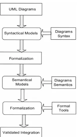
Although formal methods have a well-defined syntax and semantics but these are at the early stage of development and, hence, it needs an integrated tool support for the complete and consistent development of software systems. UML has become a de facto standard for design of object oriented systems. Therefore, it needs to define a rela- tionship between UML diagrams and formal techniques which is analyzed and established in this research.
Figure 1. Proposed integration of UML and formal meth-ods.
4.2. Formal Models
A set of definitions used in the formal model is presented in this section. The state identifier and event are repre- sented as S and Event respectively both as set types. For simple specification, the basic set types are used. In the definition of a transition from one state to another the guard is defined as a Boolean type. A state can have three possible values that are active, passive or null represented as Active, Passive and null respectively. The type of state can be simple, concurrent, non-concurrent, initial or final.
[S, Event]
Boolean ::= True False
Status ::= Active Passive Null
Type ::=Simple Concurent Nonconcurent Initial
Final
In modeling using sets, we do not impose any restric- tion upon the number of elements and a high level of abstraction is supposed. Further, we do not insist upon any effective procedure for deciding whether an arbitrary element is a member of the given collection or not. As a consequent, our sets S and Event are sets over which we cannot define any operation of set theory. For example, cardinality to know the number of elements in a set cannot be defined. Similarly, the subset, union, intersection or complement operations over the sets are not defined.
The state diagram is a collection of states related by certain types of relations. In the definition of a state, state identifier, its type, status and set of regions is required. Region is defined as a power set of sequence of states. The state is represented by a schema which consists of four
components described above. All these components are encapsulated and put in the Schema State given below. The invariants over the schema are defined in the second part of schema.
È_State______________________ ®name: S
®type: Type ®status: Status ®regions: F(seq S) Ç_______________ ®regions = 0Þ type = Simple
®# regions = 1 Þ type = Nonconcurent ®# regions > 1 Þ type = Concurent Ð__________________________
Invariants:
In the state diagram, if there is no region in a state then it is a simple state.
If there is exactly one region in a state then it is termed as non-concurrent composite state.
If there are two or more regions in a state then it is concurrent composite state.
The collection of states is represented by the schema States which consists of four variables. The mapping substates from State to power set of State describes type of a state.
È_States______________________ ®start: State
®states: F State
®substates: State §F State ®target: State
Ç_______________ ®start ä states
®start ë target ®start ä dom substates ®states ë0
®As: State | s e dom substates ¥ s e states
®As: State | s e states ¥ s ë start ¦ s ë target ¦ s . typ ë®Simple Þ s e dom substates
®target ä states
®target ä dom substates
Ð__________________________
Invariants:
The start state is not in the collection of states. The start state is not the target state.
The start state does not belong to domain of substates mapping that is it has no sub-state.
The set of states is non-empty.
For any state, s, if it is in the states and is not the start or target state and not the simple state then it belongs to domain of sub-states.
The target state does not belong to states.
The target state of the state diagram does not belong to domain of the sub-states.
fired. The transition consists of three components that are event, guard and action. Action is, in fact, a sequence of events in the definition of the transition. The transition is defined by a schema Transition in Z notation which con- sists of three variables which are event, guard and action as given blow.
È_Transition____________________ ®event: Event
®guard: Boolean ®action: seq Event
Ð__________________________
The complete state diagram is represented by the schema StateDiagram as given below. The schema con- sists of set of states of all possible events and the transition function. The transition function takes a state and se- quence of events and returns a new state.
È_StateDiagram__________________ ®States
®events: F Event
®transitions: State x Transition § State Ç_______________
®As1: State | s1 e states ¦ s1 . type ë Final
® ¥ Es2: State; tran: Transition | (s2, tran)e dom ®transitions ¥ s1 = s2
®As3: State; tran: Transition | (s3, tran)e dom transi-tions
® ¥ Es4: State | s4 e states ¥ s3 = s4 ®Aev: Event | ev e events
® ¥ Es1, s2: State; tran: Transition ® | (s1, tran)e dom transitions
® ¦ s2 e ran transitions ¦ transitions (s1, tran) = s2
® ¥ ev = tran . event v ev e ran tran . action ®As3, s4: State; tran: Transition
® | (s3, tran)e dom transitions
® ¦ s4 e ran transitions ¦ transitions (s3, tran) = s4
® ¥ Eev: Event | ev e events ¥ ev = tran . event v ev e ® ran tran . action
®As5: State; tran: Transition
® | (s5, tran)e dom transitions ¦ s5 . type ë Final ® ¥ Es6: State | s6 e states ¥ transitions (s5, tran) = s6
Ð__________________________
Invariants:
For every non final state in the state diagram, there is a transition which can be fired over it.
For every state over which a transition is fired, it must be in the collection of states of the state diagram. For every event in the set of possible events, there
must be two states and a transition over these states such that the event is in the transition and it is included in the sequence of events called action which must be executed after the guard condition of the transition is
true.
For any two states s1 and s2, there exists an event e such that transitions (s1, e) = s2.
For every non-final state there is a transition which acts on it and results a new state, that is, the transition function is defined over every non-final state. In the state diagram, it is possible that when a transition is fired, it may result the same state. The reflexive relation is satisfied over such states. That means there exists a collection of states in the state diagram over which the reflexive relation is required to be defined. Similarly, it is also possible that when a transition is fired from one state s1 to another state s2 there exists an inverse transition which can be fired from s2 to s1 that is there exists a collection of states over which the symmetric relation is defined. Finally, when a transition is fired from one state s1 to another state s2 and then a new transition is fired from s2 to s3 then a composite transition can be fired from s1 to s3 that is the transitive relation exits over the state diagram.
All of these possible relations are defined by a schema StatesRelations given below. The schema consists of four components that are state diagram, reflexive, symmetric and transitive relations. All of these components are put in the first part and invariants are defined over the relations in the second part of the schema for the well-defined-ness.
È_StatesRelations________________ ®StateDiagram
®reflexive: State j State ®symmetric: State j State ®transitive: State j State Ç_______________ ®As: State | s e states ® ¥ (s, s)e reflexive
® Û(Etran: Transition | (s, tran)e dom transi-tions
® ¥ transitions (s, tran) = s) ®As1, s2: State | s1 e states ¦ s2 e states ® ¥ (s1, s2)e symmetric
® Û(Etran1, tran2: Transition
® | (s1, tran1) e dom transitions ¦ (s2, tran2) e ®dom transitions ¥ transitions (s1, tran1) = s2 ¦ tran ®sitions (s2, tran2) = s1)
®As1, s3: State | s1 e states ¦ s3 e states
® ¥ (s1, s3)e transitiveÛ(Es2: State; tran1, tran2: ®Transition | (s1, tran1) e dom transitions ¦ s2 e states
® ¦ (s2, tran2) e dom transitions ¥ transitions ®(s1, tran1) = s2 ¦ transitions (s2, tran2) = s3)
Ð__________________________
Invariants:
reflexive over it if there exists a transition which re- sults the same state after firing the transition.
Two states are in the collection of symmetric states if there exists two transitions where each one is an in- verse of the other.
A state is in the collection of transitive states if it is one of the three states over which transitivity is defined to describe the transitive relations.
To identify and define the loops, sub-states and super- states a schema ComputingStates is described below. The schema consists of five components namely state dia- gram, input state, loops, sub-states and super-states. The state diagram is given as input in the schema for all the functions computing loops, sub-states and super-states of a given state. The loops variable returns all the states over which transition function returns the same state. The subs! variable computes all the possible sub-states, if exist, of a given state. And similarly the sups! variable evaluates all the possible super-states, if exist, of a given state.
È_ComputingStates_______________ ®StateDiagram
®state?: State ®loops!: F State ®subs!, sups!: F State Ç_______________ ®state? e states
®loops!
® = { s: State; tran: Transition
®| (s, tran)e dom transitions ¦ transitions (s, tran) = s ¥s}
®subs! = { s: State; tran: Transition
® | (state?, tran)e dom transitions ¦ transitions ®(state?, tran) = s ¥ s }
Ð_________________________
Invariants:
The input state must belong to collection of all the states of the state diagram.
The loops are computed by taking a state and the transitions which return the same state.
The sub-states of a given state are calculated by using the recursive definition of the transition function. The super-states of a given state are calculated by
using the recursive definition of the inverse of the sequence of transition functions by changing the source and target states with each other.
In this section, a sequence of possible transitions and events of the state diagram is described when moving from one state to another of the diagram. The specifica- tion is given using the schema Protocol which consists of four components named as state diagram, sequence of transitions, start state and target state. From start state the protocol is initiated, at end state it is ended. And the se-
quence of transitions is used to move from start to end state. The algorithm of moving from start to final state is given below in addition to few invariants required.
È_Protocol___________________ ®StateDiagram
®protocol: seq Transition ®start: State
®target: State
Ç_______________
®start e states ¦ target e states ¦ 1 ø # protocol ®Es: State; tran: Transition; evts: seq Event ® | (start, tran)e dom transitions
® ¦ transitions (start, tran) = s ¦ tran . guard = True ® ¦ start . status = Active ¦ s . status = Passive ® ¦ 1 ø # evts ¦ tran . event = evts 1
® ¦(Ai: N| i e 1 .. # evts - 1 ¦ i + 1 ø # evts ® ¥ ((tran . action, i)e applies$to
® ¦ evts (i + 1) = tran . action i))¥ protocol 1 = tran
®Ai: N| i e dom protocol ¦ 2 ø i ¦ i ø # protocol - 1 ®¥ Es1, s2: State; tran: Transition; evts: seq Event ® |(s1, tran) e dom transitions ¦ transitions (s1, tran) = s2
® ¦ tran . guard = True ¦ 1 ø # evts¦ tran . event = evts 1 ® ¦(Ai: N| i e 1 .. # evts - 1 ¦ i + 1 ø # evts
® ¥ ((tran . action, i)e applies$to
® ¦ evts (i + 1) = tran . action i))¥ protocol i = tran ®Es: State; tran: Transition; evts: seq Event
®|(s, tran)e dom transitions¦ transitions (s, tran) = target
® ¦ tran . guard = True ¦ s . status = Active ® ¦ target . status = Passive ¦ 1 ø # evts
® ¦ tran . event = evts 1 ¦(Ai: N| i e 1 .. # evts - 1 ¦ i ®+ 1 ø # evts ¥ ((tran . action, i)e applies$to ®¦ evts (i+1)= tran .action i))¥protocol (# protocol) = tran
Ð_________________________
Invariants:
The start state is in collection of states of the dia- gram.
The target state belongs to the collection of the states.
There exists a transition which takes start state and a sequence of events and returns the next possible state.
There exists a sequence of transition(s) possibly single transition which takes state next to start state and traverses to reach the state previous to the target state.
There exists a transition which takes the state pre- vious to target and returns the target state.
schema Protocols of type power set of Protocol is de- fined. The schema describes the possible ways by using a recursive definition of the Protocol schema as given be- low.
È_Protocols____________________ ®protocols: F Protocol
Ç_______________
®Apr: Protocol | pr e protocols ¦ pr . protocol ® eF(Zx:action: P(Zx Event); event: Event; guard: ®Booleanò)¥ pr . start e pr . states ¦ pr . tar-get e pr . ®states ¦ 1 ø # pr . protocol
®Apr: Protocol | pr e protocols ¦ pr . protocol ® eF(Zx:action: P(Zx Event); event: Event; guard: ®Booleanò)¥ Es: State; tran: Transition; evts: seq Event
®| (pr . start, tran)e dom pr . transitions
®¦(pr . transitions,(pr . start, tran))e applies$to ®¦ pr . transitions (pr . start, tran) = s
®¦ tran . guard = True ¦ pr . start . status = Active ®¦ s . status = Passive ¦ 1 ø # evts ¦ tran . event = evts 1 ®¦(Ai: N| i e 1 .. # evts - 1 ¦ i + 1 ø # evts
®¥ ((tran . action, i)e applies$to
®¦ evts (i + 1) = tran . action i))¥ pr . protocol 1 = tran
®Apr: Protocol | pr e protocols ¦ pr . protocol ®eF(Zx:action: P(Zx Event); event: Event; guard: ®Booleanò)
® ¥ Ai: N| i e dom pr . protocol ¦ 2 ø i ¦ i ø # pr . ®protocol - 1 ¥Es1,s2:State;tran:Transition; evts: seq Event ® | (s1, tran)e dom pr . transitions
® ¦ pr . transitions (s1, tran) = s2 ¦ tran . guard = True
® ¦ 1 ø # evts ¦ tran . event = evts 1
® ¦(Ai: N| i e 1 .. # evts - 1 ¦ i + 1 ø # evts ® ¥ ((tran . action, i)e applies$to
® ¦ evts (i + 1) = tran . action i))¥ pr . protocol i = tran
Ð__________________________
Invariants:
For a protocol, there exists a transition and sequence of events which take start to the next possible state. There exists a sequence of transition(s) and sequence
of sequence of events which traverses all the possible states except the start and target states.
For each protocol, there exists a transition and se- quence of events which reaches to the target state based on the above recursive definition of protocol.
5. Conclusion and Future Work
Unified Modeling Language (UML) is used at initial phases because of having much support of diagrams whereas formal methods are useful at the later stages of software development because of having rigorous mathe- matical and computer tools support. In this way, UML and
Formal Methods are both useful for design and specifica- tion of software systems therefore integration of these approaches was required for a systematic development. To facilitate the software development process an auto- matic generation of specification from diagrams will be much useful to capture the hidden semantics under the UML diagrams. In this research, UML state diagram is linked and formalized using Z achieving above objective. The most relevant work [38-40] was considered as start- ing point for this research. In addition to above following benefits are observed: 1) An approach is developed by linking UML to Z notation by defining a relationship among fundamentals of these semi-formal and formal techniques; 2) The reusability issue is addressed by de- fining the components and developing recursive approach to be useful easing the development process; 3) The re- sultant approach will be useful in the systems develop- ment and construction of automated tools for generating specification from the UML state diagram; 4) Mostly, students use UML for designing the projects, this new approach will facilitate them to improve the design at initial stages of their project development.
The research work on formalization of some other important diagrams, using Z notation, of UML including use case and sequence diagrams is in process and will appear soon.
6. Acknowledgements
I would like to acknowledge Software Engineering Re-search Group at the Department of Computer Science, King Faisal University, for their valuable comments.
REFERENCES
[1] B. Akbarpour, S. Tahar and A. Dekdouk, “Formalization of Cadence SPW Fixed-Point Arithmetic in HOL,”
Formal Methods in System Design, Vol. 27, 2005, pp.
173-200. doi:10.1007/s10703-005-2256-8
[2] N. H. Ali, Z. Shukur and S. Idris, “A Design of an Assessment System for UML Class Diagram,” Inter- national Conference on Computational Science and App-
lications, Kuala Lumpur, 26-29 August 2007, pp. 539-
546.
[3] K. Araki, A. Galloway and K. Taguchi, “Using a Process Algebra to Control B Operations,” Proceedings of 1st
International Conference on Integrated Formal Methods,
Springer-Verlag, London, 1999, pp. 437-456.
[4] H. Beek, A. Fantechi, S. Gnesi and F. Mazzanti, “State/ Event-Based Software Model Checking,” Proceedings of
4th International Conference on Integrated Formal Me-
thods, Springer, Canterbury, Vol. 2999, 2004, pp. 128-
147.
9, No. 8, 2010, pp. 1521-1556. doi:10.3923/itj.2010.1521.1556
[6] R. Borges and A. Mota, “Integrating UML and Formal Methods,” Electronic Notes in Theoretical Computer
Science, Vol. 84, 2003, pp. 97-112.
[7] M. Brendan and J. S. Dong, “Blending Object-Z and Timed CSP: An Introduction to TCOZ,” Proceedings of
International Conference on Software Engineering, Kyoto,
19-25 April 1998, pp. 95-104.
[8] W. S. Changchien, J. J. Shen and T. Y. Lin, “A Preli- minary Correctness Evaluation Model of Object-Oriented Software Based on UML,” Journal of Applied Sciences, Vol. 2, No. 3, 2002, pp. 356-365.
doi:10.3923/jas.2002.356.365
[9] A. Dennis, B. H. Wixom and D. Tegarden, “Systems Analysis and Design with UML,” 3rd Edition, Wiley, New York, 2005, 576 p.
[10] Z. Derakhshandeh, B. T. Ladani and N. Nematbakhsh, “Modeling and Combining Access Control Policies Using Constrained Policy Graph,” Journal of Applied Sciences, Vol. 8, 2008, pp. 3561-3571.
doi:10.3923/jas.2008.3561.3571
[11] J. Derrick and G. Smith, “Structural Refinement of Object-Z/CSP Specification,” Proceedings of 2nd Inter-
national Conference on Integrated Formal Methods, Spr-
inger-Verlag, London, Vol. 1945, 2000, pp. 194-213. [12] S. A. Ehikioya and B. Ola, “A Comparison of Formalisms
for Electronic Commerce Systems,” Proceedings of In-
ternational Conference on Computational Cybernetics,
Vienna, 30 August-1 September 2004, pp. 253-258.
[13] F. Gervais, M. Frappier and R. Laleau, “Synthesizing B Specifications from EB3 Attribute Definitions,” Pro-
ceedings of 5th International Conference on Integrated
Formal Methods, Springer, Berlin, Vol. 3771, 2005, pp.
207-226.
[14] A. Hall, “Correctness by Construction: Integrating For- mality into a Commercial Development Process,” Pro- ceedings of International Symposium of Formal Methods
Europe, Vol. 2391, 2002, pp. 139-157.
[15] K. E. Hamdy, M. A. Elsoud and A. M. El-Halawany, “UML-Based Web Engineering Framework for Modeling Web Application,” Journal of Software Engineering, Vol. 5, No. 2, 2011, pp. 49-63. doi:10.3923/jse.2011.49.63
[16] O. Hasan and S. Tahar, “Verification of Probabilistic Properties in the HOL Theorem Prover,” Proceedings of
the Integrated Formal Methods, Vol. 4591, 2007, pp
333-352. doi:10.1007/978-3-540-73210-5_18
[17] X. He, “Formalizing UML Class Diagrams: A Hiera- rchical Predicate Transition Net Approach,” Procee-
dings of 24th Annual International Computer Software
and Applications Conference, Taipei, 25-28 October 2000,
pp. 217-222.
[18] M. Heiner and M. Heisel, “Modeling Safety Critical Systems with Z and Petri-Nets,” Proceedings of Inter-
national Conference on Computer Safety, Reliability and
Security, Springer-Verlag, London, 26-28 October 1999,
pp. 361-374. doi:10.1007/3-540-48249-0_31
[19] D. Jackson, I. Schechter and I. Shlyakhter, “Alcoa: The Alloy Constraint Analyzer,” Proceedings of International
Conference on Software Engineering, Limerick, 4-11
June 2000, pp. 730-733.
[20] H. Leading and J. Souquieres, “Integration of UML and B Specification Techniques: Systematic Transformation from OCL Expressions into B,” Proceedings of 9th Asia-
Pacific Software Engineering Conference, Gold Coast,
4-6 December 2002, p. 495. doi:10.1109/APSEC.2002.1183053
[21] Liu and C. Chen, “An Improved Quasi-Static Scheduling Algorithm for Mixed Data-Control Embedded Software,”
Journal of Applied Sciences, Vol. 6, No. 7, 2006, pp.
1571-1575. doi:10.3923/jas.2006.1571.1575
[22] Z. M. Ma, “Fuzzy Conceptual Information Modeling in UML Data Model,” International Symposium on Com-
puter Science and Computational Technology, Shanghai,
20-22 December 2008, pp. 331-334. doi:10.1109/ISCSCT.2008.353
[23] R. Miles and K. Hamilton, “Learning UML 2.0,” 1st Edition, O’Reilly Media, Sebastopol, 2006, 288 p. [24] A. Moeini and R. O. Mesbah, “Specification and Deve-
lopment of Database Applications Based on Z and SQL,”
Proceedings of International Conference on Information
Management and Engineering, Kuala Lumpur, 3-5 April
2009, pp. 399-405.
[25] A. M. Mostafa, A. I. Manal, E. B. Hatem and E. M. Saad, “Toward a Formalization of UML2.0 Meta-Model Using Z Specifications,” Proceedings of 8th ACIS International
Conference on Software Engineering, Artificial Intelligence,
Networking and Parallel/Distributed Computing, Qingdao,
Vol. 3, 2007, pp. 694-701. doi:10.1109/SNPD.2007.508 [26] H. Podeswa, “UML for IT Business Analyst,” 2nd Edi-
tion, Course Technology, 2009, 372 p.
[27] T. B. Raymond, “Integrating Formal Methods by Uni- fying Abstractions,” Springer, Berlin, Vol. 2999, 2004, pp. 441-460.
[28] S. Sengupta and S. Bhattacharya, “Formalization of UML Diagrams and Consistency Verification: A Z Notation Based Approach,” Proceedings of India Software Engi-
neering Conference, Hyderabad, 19-22 February 2008, pp.
151-152. doi:10.1145/1342211.1342248
[29] Z. Shi, “Intelligent Target Fusion Recognition Based on Fuzzy Petri Nets,” Information Technology Journal, Vol. 11, No. 4, 2012, pp. 500-503.
doi:10.3923/itj.2012.500.503
[30] M. Shroff and R. B. France, “Towards Formalization of UML Class Structures in Z,” 21st International Con-
ference on Computer Software and Applications, Wash-
ington, 11-15 August 1997, pp. 646-651.
[31] J. M. Spivey, “The Z Notation: A Reference Manual,” Prentice-Hall, Englewood Cliffs, 1989.
[32] J. Sun, J. S. Dong, J. Liu and H. Wang, “A XML/XSL Approach to Visualize and Animate TCOZ,” Proceedings
of 8th Asia-Pacific Software Engineering Conference,
Macao, 4-7 December 2001, pp. 453-460.
national Conference on Computer & Information Tech-
nology, Wuhan, 14-16 September 2004, pp. 1116-1121.
[34] J. M. Wing, “A Specifier, Introduction to Formal Me- thods,” Computer Journal, Vol. 23, No. 9, 1990, pp. 8-24. doi:10.1109/2.58215
[35] Z. Xiuguo and H. Liu, “Formal Verification for CCML Based Web Service Composition,” Information Tech-
nology Journal, Vol. 10, No. 9, 2011, pp. 1692-1700.
[36] C. Yong, “Application of Wu’s Method to Proving Total Correctness of Recursive Program,” Information Tech-
nology Journal, Vol. 9, No. 7, 2010, pp. 1431-1439.
doi:10.3923/itj.2010.1431.1439
[37] N. A. Zafar and F. Alhumaidan, “Transformation of Class Diagrams into Formal Specification,” International Jour-
nal Computer Science and Network Security, Vol. 11, No.
5, 2011, pp. 289-295.
[38] S. Zarina, N. Alias, M. M. Halip and B. Idrus, “Formal Specification and Validation of Selective Acknowledge- ment Protocol using Z/EVES Theorem Prover,” Journal
of Applied Sciences, Vol. 6, No. 8, 2006, pp. 1712-1719.
doi:10.3923/jas.2006.1712.1719
[39] Z. X. Wu, H. He, L. Chen and Y. Zhang, “Ontology Based Semantics Checking for UML Activity Model,”
Information Technology Journal, Vol. 11, No. 3, 2012, pp.
301-306. doi:10.3923/itj.2012.301.306