Active Stirling Engine
Vinod Kumar Gopal
Dept. of Electrical & Computer Engineering,
University of Canterbury, Christchurch, New Zealand.
Email: [email protected]
Dr. Richard Duke,
Dept. of Electrical & ComputerEngineering,
University of Canterbury, Christchurch, New Zealand
Email: [email protected]
Dr. Don Clucas,
Technical Director, Whisper Tech Ltd, Christchurch, New Zealand Email: [email protected]
Abstract—In this paper the WhisperGen™ micro combined heat and power (microCHP) system, its advantages, control and possible scope for improvement are explored. Concept of active Stirling engine (ASE) is introduced. A test rig designed to test possible improvements of the efficiency and controllability of a kinematic Stirling engine based microCHP system is explained.
I. INTRODUCTION
Traditional combined heat and power systems (CHP) are large scale installations that make use of the heat produced by a power station to provide heating and hot water. This improves the efficiency of the generation process, but has the disadvantage of being limited to use in industry or properties that are located very close to the power station.
A microCHP system utilises the same principles, but uses a small single home scale generating unit that is installed as an alternative to a standard domestic boiler. When operating, the microCHP system generates both electricity and hot water. The electricity produced is available for use in the house or sent to the national grid and the hot water is used for both central heating and domestic hot water.
Fig: - 1. Diagram showing the energy flows in a WhisperGen™ micro CHP system [1]
The electrical efficiency of microCHP systems in development is 10 to 20% and overall energy recovery efficiency is above 90%. The use of a microCHP system can play an important role in the effort to reduce the atmospheric pollution and carbon dioxide emissions, a leading contributor to climate change. Better efficiency will also allow better utilisation of natural resources.
Heat engines are generally described in terms of cyclic processes in which a gas absorbs heat at a high temperature, releases heat at a lower temperature and performs an amount of work. Carnot showed in the 1820s that the maximum theoretical efficiency available from a reversible heat engine depends only on the temperature change in the cycle.
η = QW
e = 1-
Tc
Te (1)
η is the efficiency, W is the work done by the engine, Qe is the
heat fed to the engine, Tc is the temperature at which heat is
rejected and Te is the temperature at which heat is absorbed.
The ideal Stirling cycle, illustrated in figures (2) and (3), is a highly idealised thermodynamic cycle, comprised of four thermodynamic processes, including two isothermal and two constant volume processes. The theoretical efficiency of a Stirling cycle operating between high temperature Te and low
temperature Tc is the same as that of the Carnot cycle. Heat is
supplied to the cycle at Te. Part of the heat is converted to
work and part of it is rejected as heat at a lower temperature Tc. The displacer is not a piston and is used to transfer the gas
between hot and cold ends.
Fig: - 2. Sequence of ideal piston and displacer motions of a Stirling engine [2]
Process 1-2 is isothermal compression at temperature Tc
Process 2-3 is constant volume transfer of gas from the cold section to the hot section of the engine
Process 3-4 is isothermal expansion at temperature Th
Process 4-1 is the constant volume cooling
In a conventional engine, the piston and the displacer will be moving nearly sinusoidally. Friction and the transfer of heat across finite temperature gradients reduce the actual efficiency. Piston and displacer motion profiles of a conventional Stirling engine is shown is figure (4). In the operation of this engine, a significant departure from ideality arises as a consequence of the near sinusoidal motion of the pistons. The compression and expansion do not take place wholly in one or other of the two spaces.
Fig: - 4. Motion profile of a real Stirling engine [4]
Sinusoidal piston and displacer motion leads to the following pressure volume diagram (fig: 5) for a kinematic Stirling engine. The work done by the engine is the area enclosed by the pressure volume diagram.
Fig: - 5. Measured pressure volume diagram of a conventional Stirling engine
The Stirling engine in the WhisperGen™ microCHP system (figure 6) has four pistons that are driven by the expansion and contraction of nitrogen gas (the working gas), which is sealed in the engine under pressure. The Stirling engine is also known as an external combustion engine. The working gas expands when it is heated by fuel burned in a combustion chamber located outside the cylinders (rather than within the cylinders as in the internal combustion engine used in motor cars).
Fig: - 6. What is inside the enclosure of WhisperGenTM
1. An Electrical generator that provides 230V AC power
2. A Stirling engine that provides motive power for the generator
3. A gas burner assembly which provides heat necessary for the
operation of the Stirling engine
4. A heat exchanger that recovers heat from the hot gases produced
by the burner
5. A auxiliary burner that provides additional heat at times of high
heat demand
6. An exhaust fan connected to a balanced flue. This provides the
combustion air for the burner and passes the hot gases from the combustion process to the atmosphere
WhisperGen™ microCHP systems are the size of a domestic dishwasher. They produce heat and power at the point of demand. The system avoids distribution losses and maximises utilisation of primary energy and offers significant contribution to CO2 mitigation targets [5]. The WhisperGen™
microCHP system offer significant improvement over condensing boilers.
piped out to the heating system. At times of high heat demand an auxiliary burner provides additional heating.
[image:3.612.57.289.161.310.2]Power generated and combustion air Vs time is shown in figure (7). Initial power generated rises above 1000 watts. The closed loop control system is controlling the quantity of combustion air and fuel to stabilise the power produced to 1000 watts. This data is collected during a heat demand cycle of 27 minutes.
Fig: - 7. Data from a WhisperGen™ micro CHP system is shown during a 27 minute heat demand
In microCHP systems, electric power is generated when the system is running. Primary control of microCHP systems is the heat demand signal, which starts and stops the engine. MicroCHP systems are sized to handle the average thermal load of a house. An auxiliary burner (also called the boost burner) is used in the system to increase the thermal output as and when required. The auxiliary burner is coupled to the main exhaust heat exchanger and is turned on to increase the heat output.
In normal operation, the auxiliary burner is switched on and off to achieve the control aspect (outer control loop) for the heating. The disadvantage of using an auxiliary burner is that the energy going into the auxiliary burner is not generating electricity. This part of the system works like a conventional boiler.
Current microCHP systems do not have a good degree of ‘controllability’ over the proportions of heat and electricity produced. MicroCHP systems employ ON-OFF control for the auxiliary burner and primary burner. The system turns off when the primary coolant reaches the set temperature and turns on when the coolant temperature hits the lower level. Table 1 shows the hours of operation of main burner and auxiliary burners. This data is taken on a sample of 62 engines running for a total of 92,730 hours.
Sample Size # of Engines
Run
Hours # of Starts
KWH
Generated Boost Hours
62 92730 124067 79317 10662
Average 1496 2001 1279 172
Table: - 1. Sample data showing operation of 62 WhisperGen™ systems
II. PROPOSED SCHEME
Conventional Stirling engines are passive types. The displacer is connected to the same crank shaft and will follow the piston in a mechanical fashion, mostly maintaining the same phase relationship. Actively controlled Stirling engines or Active Stirling engine (ASE) has the capability to control the displacer motion trajectory based on an external command signal. ASE can control the speed, stroke, phase, motion profile, etc of the displacer to achieve different results from the same engine.
Automobile industry is moving towards a similar concept with variable valve timing and active injection systems to improve the performance of IC engines.
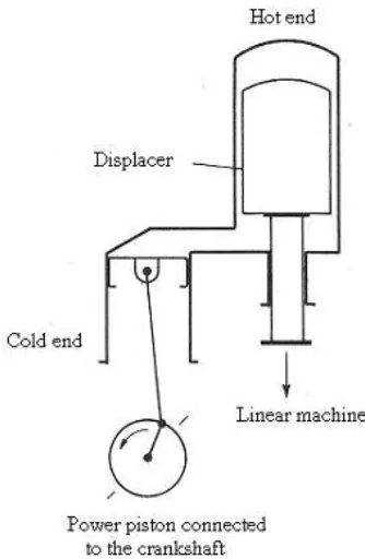
[image:3.612.331.498.279.535.2]In the proposed scheme shown in figure (8), the displacer is disconnected from the crankshaft and is driven by a linear electrical machine.
Fig: - 8. Proposed system with the displacer connected to a linear electrical machine
Fig: - 9. Motion profile of the piston and displacer in the proposed system. XD and XP are the positions of displacer and piston respectively. Stroke is 2L. This is similar to an overdriven Ringbom type Stirling engine [6]
The motion profile of the displacer piston is controlled with dwell at both the ends of stroke as shown in figure (9).
[image:4.612.318.561.464.648.2]Position encoders provide the position information of the piston and displacer to the control system. The closed loop control system resolves the displacer position and provides command signals to the servo drive for the linear machine. A trajectory generator is implemented in motion control software, so that complex motion profiles can be resolved in real time. The non-linear motion of the displacer increases the area enclosed by the pressure volume diagram as shown in figure (10).
Fig: - 10. Pressure volume diagram of an ideal cycle, a conventional Stirling engine with near sinusoidal piston motions and the proposed non-linear drive system. The shaded area represents extra work done due to non linear displacer motion
The shaded area shows the loss recovery potential using the proposed system. The following equation shows the relationship between the work done and the area enclosed by the PV diagram in an ideal Stirling engine.
W= Qe- Qc= ׯp dVe- ׯp dVc (2)
In an ideal engine, the net work done is the difference between the heat absorbed Qe and the heat rejected, Qc. The expansion
space pressure volume diagram and the compression space pressure volume diagram reveal the net work done by a Stirling cycle engine. The proposed scheme allows the closed integral to be larger due to the non linear motion and hence relates to an increase in indicated power produced by the engine.
III. TESTRIG
The following describes a test rig to be used to investigate the benefits of an engine with non linear displacer motion.
A 4 cylinder WhisperGenTM engine block and lower housing is converted to the test rig. Three of the cylinder ports are closed in the engine block and one of the cold ends and a simple power piston is used to work as a Gamma configuration engine. A wobble yoke is used as the transmission. The hot end heater head with the displacer is mounted in transverse direction on top of the cold end. Vacuum brazed electric heating coils are used on the heater head to provide the necessary heat input. The heater coil is powered from a laboratory power supply to control the power input at the hot end.
A linear electrical machine (Parker Hannifin ML-50 ironless linear servo motor) and a servo controller (ACR 9000) is used for controlling the displacer motion profile of a custom Stirling engine powering a micro combined heat and power system. The displacer operates with a stroke of 25mm and a speed up to 1500 RPM. The displacer can dwell up to 40% of the time at the end of stroke to create non linear motion.
[image:4.612.60.295.469.617.2]Fig: - 12. Displacer motion with 10ms dwell at end of stroke. Stroke is 25mm and speed is 600 RPM. Dwell is 33% of the total cycle time.
Figures 11 and 12 show sinusoidal and non linear motion of the displacer. A linear encoder feeds back the position of the displacer to the servo controller to control the displacer position in closed loop. A transmission converts the linear piston motion to rotary motion suitable for the rotary electrical machine. A 3phase AC induction machine is used as the electrical machine. The 3 phase machine starts the engine and generates electric power when the active Stirling engine is generating. The 3phase AC machine is driven by its own electrical drive so that speed control of the engine can be achieved. A load bank is connected between the three phase machine and its drive to absorb the electrical power generated. A rotary encoder connected to the AC machine shaft gives the position of the shaft at any point in time. A second linear encoder provides the position of the power piston for improved accuracy in measuring power piston position.
The test rig is pressurized to 22bar with nitrogen as the working fluid. Rotating shaft from the 3phase AC machine is brought out of the pressure vessel through a rotary seal before coupling to the rotary encoder. Displacer rod is also brought out through a linear seal before coupling to the linear machine.
ASE test rig is instrumented with pressure sensors, temperature sensors and coolant flow sensors. Pressure sensors measure the pressure at the hot end, cold end and the crank case pressure. All transducers are connected to a National Instruments LabVIEW based CompactDAQ data acquisition system. Data acquisition system is triggered from the pulses from the shaft encoder. The data acquisition system acquires linear encoder positions on the power piston and the displacer, pressure at the expansion space, compression space and the crank case, Temperature of the heater head, coolant in, coolant out, gas transfer port and ambient temperature. Multiple points per cycle are acquired to provide a pressure volume (PV) diagram and calculate the indicative thermodynamic power generated by the engine. Work done by the engine is the area enclosed by the PV diagram and can be easily calculated by numerical integration. Shaft or electrical power output is not
measured as the indicated power is the most reliable comparative measure.
The drive of the 3 phase AC machine controls the speed of the test rig. Linear machine will track the position and drive the displacer in the required motion profile. ASE displacer can be driven sinusoidal with optimum phase angle to collect a reference PV diagram. The system can then drive the displacer in non linear fashion with specified dwell at both the ends of the stroke to increase the area within the PV diagram. A LabVIEW based system collects data and numerically integrates the PV diagram to calculate the indicated power to determine the efficiency improvement.
Fig: - 13. Actively controlled Stirling engine test rig
ASE is started using the 3phase AC machine acting as a motor. The linear machine driving the displacer follows suit depending on the programmed motion profile. Once the system is thermally stabilised, the data acquisition system is triggered to capture the power piston and displacer positions, pressure, temperature and coolant flow data.
IV. CONCLUSION
A test rig to study the performance of a high speed kinematic Stirling engine with non linear displacer motion is developed. A servo control system was developed to drive the linear machine controlling the displacer. A LabVIEW based data acquisition system is developed to collect the data generated by the test rig.
ACKNOWLEDGMENT
REFERENCES
[1] WhisperGen™ (MkVb) microCHP System Design Manual
[2] G. Walker, G. Reader, O.R. Fauvel, E.R. Bingham, “The Stirling
Alternative”, Department of Mechanical Engineering, The University of Calgary. ch.1-7
[3] James R Senft, “Ringbom Stirling engines”, Oxford University Press,
New York, 1993. ISBN 0-19-507798-9 Page 9
[4] James R Senft, “Ringbom Stirling engines”, Oxford University Press,
New York, 1993. ISBN 0-19-507798-9 Page 26
[5] Jeremy Harrison, EA Technology, Micro Combined heat and power
[6] James R Senft, “Ringbom Stirling engines”, Oxford University Press,