Trapping in a Material World
Susan E. Skelton Spesyvtseva*
and Kishan Dholakia*
SUPA, School of Physics and Astronomy, University of St. Andrews, North Haugh, St. Andrews, Fife, KY16 9SS, United Kingdom
*
S Supporting InformationABSTRACT: The ability to manipulate small particles of matter using the forces of light, optical trapping, forms the basis of a number of exciting research areas, spanning funda-mental physics, applied chemistry and medicine and biology. Historically, a largely unexplored area has been the influence of the material properties of the particle on the optical forces. By taking a holistic approach in which the properties of the particle are considered alongside those of the light field, the forcefield on a particle can be optimized, allowing significant increases of the optical forces exerted and even the introduc-tion of new forces, torques, and other physical effects. Here we present an introduction to this newly emerging area, with a
focus on high refractive index and antireflection coated particles, nanomaterial particles, including metallic nanoparticles, optically anisotropic particles, and metamaterials. Throughout, we discuss future perspectives that will extend the capabilities and applications of optical trapping and shape future avenues of research in this burgeoningfield.
KEYWORDS: optical trapping, material, antireflection, nanomaterials, chiral, birefringent
O
ptical trapping, the ability to manipulate small particles of matter using the power of light, has matured into a major area of cutting edge science and application since its inception in the 1970s. Both a research area of fundamental interest and an enabling tool for a wide range of applications including cell and single molecule biophysics, nanoscience, and plasmonics, thefield spans fundamental to applied research and has maintained a broad audience across physics, chemistry and biomedicine.
Thefield is based on the use of light to influence the motion of mesoscopic particles. In optical tweezers, the most common configuration, a micro- or nanoscale object is trapped at the focus of a tightly focused laser beam using optical forces, as illustrated in Figure 1a. A standard optical tweezers setup uses a single Gaussian laser beam to trap and manipulate the position of a single dielectric particle, typically made of silica or polystyrene. However, the optical forces on the particle depend crucially on the interaction between the laserfield and the particle. Therefore, the degree of control over the optical forces can be greatly increased by controlling key parameters of either the beam or the particle.
One approach is to shape the profile of the laser beam,1,2in either phase3 or polarization,4 and while this will be briefly discussed later in the article, more information can be found in the review by Dholakia and Čižmár.1The second approach is to control the properties of the particle, either by modifying its shape5,6for two-7or three-dimensional8trapping or the material from which it is made. The use of novel materials for optical trapping beyond the more commonly used dielectric beads, can enhance the optical forces, facilitating trapping of previously untrappable categories of particles. A judicious choice of material can even introduce new and different forces to a trap allowing the directions of forces to be reversed or to apply torques and rotational motion to a trapped particle.
By taking a holistic approach in which the properties of the particle are considered alongside those of the lightfield, the force
field on a particle can be optimized and tailored to the desired application.
Other published reviews on optical trapping have not considered the largely untapped potential of the material pro-perties of the particle. This review aims to show how changing the material of the trapped object extends the capabilities and applications of optical trapping in new and intriguing ways and offers some perspectives on this rapidly emerging area.
■
PHYSICS OF OPTICAL FORCES AND THE EFFECTSOF KEY MATERIAL PARAMETERS
The optical force on a particle originates from the interaction with the light field, therefore the material properties of the particle strongly affect both the magnitude and direction of the resultant force.
Although a detailed discussion of how to calculate the optical forces acting on a particle is beyond the scope of this article,9the introduction of several key equations and dependencies upon pertinent physical parameters leads to valuable insight into the effects of various particle properties on the optical forces. In particular, by considering the dependence of the optical forces on properties including the particle polarizability, the particle refractive index, and the size of the particle, we glean important insights into how the material properties of particles may be
Received: January 12, 2016 Revised: April 5, 2016 Accepted: April 5, 2016
Perspective
pubs.acs.org/journal/apchd5
© XXXX American Chemical Society A DOI:10.1021/acsphotonics.6b00023 ACS PhotonicsXXXX, XXX, XXX−XXX
License, which permits unrestricted use, distribution and reproduction in any medium,
chosen and tailored in order to optimize the optical forces for specific applications.
Optical Force,F.The optical force,F, on a particle of radius,
r, and volume,Ω, is given by10
∫
⟨ ⟩ = ̂⟨ ⟩ Ω
Ω
F r2 r TM d
(1) The Minkowski form of the Maxwell stress tensor,⟨TM ⟩, is defined as
μμ
μμ
⟨ ⟩ = ϵ ϵ ⊗ * + ⊗ *
− ϵ ϵ · * + · *
E E H H
E E H H I
TM 1
2Re( )
1
2( )
r 0 r 0
r 0 r 0 (2)
where⊗represents the dyadic product,Iis the unit dyadic,Eis the electricfield, andHis the magneticfield. The constantsϵr
andμrare the material’s relative permittivity and permeability, respectively. Together, these constants determine how electro-magneticfields propagate through the material.
An alternative definition, proposed by and named after Max Abraham does not include the material properties thus the resultant momentum represents the momentum stored in the electromagneticfield. The Minkowski definition, however, includes the momentum of matter that interacts with the electromagnetic
field; thus, this approach is particularly useful when calculating the interaction between light and matter and the resultant optical forces.11
[image:2.625.130.496.66.507.2]We can gain deeper insight into the effects of the material properties by employing the dipole approximation to consider
Figure 1.(a) Illustration of a single-beam optical trap/optical tweezers, where a particle is trapped at the focus of a tightly focused beam; (b) Geometric ray optics picture demonstrating the momentum of photons impinging at normal incidence on a particle with refractive index,np, greater than the
surrounding medium,nm.δpis the momentum difference; (c, d) Geometric ray optics diagrams illustrating the origin of the optical gradient force for
non-normal incident rays in a tightly focused beam:wis the Gaussian beam waist,δpscis the component of momentum transfer that contributes to the
scattering force; (e) Calculated real component of polarizability (usingeq 6) for a dipolar dielectric particle with radius 1μm as a function of particle refractive index,np, suspended in water,nm= 1.3, for a trapping wavelength ofλ= 800 nm; (f) Calculated scattering cross-section (usingeqs 6and9) as a
function of particle refractive index for the same parameters as in (e).
optical forces acting on spherical particles significantly smaller than the optical wavelength,λ. Wherekr≪1 and|n |
n
p
m
kr ≪1
(wherek= 2πλnm
,nmis the refractive index of the surrounding
medium andnpis the refractive index of the particle), the optical
force can be rewritten as12
∑
α⟨ ⟩ =F E r ∇ *E r |=
1
2Re( i p i( )1 i ( )r r1)
(3) whereαpis the polarizability of the particle.
By employing appropriate vector identities and the Maxwell-Faraday equation,∇×E=iωμ0H, the dipole force ineq 3may be
expressed as13
α σ α σ α
ω
⟨ ⟩ = ∇| | + × * +
∇ ×⎜⎛ ϵ × *⎟ ⎝
⎞ ⎠
F E
c E H c
iE E 1
4Re( )
( )
2 Re( ) ( )
4 p 2 p p 0 (4) Thefirst term ineq 4represents the optical gradient force, as it is proportional to the gradient of the irradiance of thefield.14,15 This is a conservative force that results in particles with a high refractive index relative to their surroundings being pulled toward the region of maximum light intensity. In an optical tweezers, this is the focal volume of the light beam.
The second and third terms in eq 4 represent a non-conservative scattering force,16,17 proportional to the total particle cross-section,σ(αp).
13
The second term is the radiation pressure force that acts to push the particle in the direction of the Poynting vector,S = μ1E× *B
0
. Until recently, the scattering
force was considered to consist solely of the radiation pressure force. However, more recently, an additional nonconservative contribution to the scattering force arising in a lightfield with nonuniform helicity has been introduced,13represented by the third term ineq 4. The so-called“spin curl force”is associated with the nonuniform distribution of the spin density of the light
field. The spin curl force is zero for a plane wave but can be significant for a tightly focused beam in an optical tweezers.
Particle Polarizability,αp.Equation 4shows that each of
the three optical forces on a particle depend on a key material property of the particle: the polarizability,αp. The polarizability is
a measure of the tendency of a material to become polarized in response to an applied electricfield,E, and (where the electric
field is not sufficiently large as to induce nonlinear effects18) is defined as the ratio of the induced dipole moment p to the electricfield that produces this dipole moment:p=αpE.
Effect of the Polarizability on the Optical Gradient Force. Equation 4indicates that the gradient force on a dipolar particle is proportional to the real part of the polarizability:
α
= ∇⟨| | ⟩
F 1 E
4Re( )
grad p 2 (5)
therefore, the magnitude of the gradient force acting on a particle can be maximized by choosing to use a particle with a high relative polarizability.
We can better understand how to achieve this by consider-ing the form of the polarizability for small dielectric particles,19 where
α α
α π
=
−i k ϵ
1 /6
p 0
0 03 0 (6)
and
α = π ϵ −
+ ⎛ ⎝ ⎜ ⎞ ⎠ ⎟
n r m
m
4 1
2 0 m2 0 3
2
2
(7) is the Clausius-Mossotti relation.
In this case, the polarizability is a function of both the size of the particle, r, and the relative refractive index of the particle compared to its surrounding medium,m=np/nm, wherenpis the
refractive index of the particle andnmis the refractive index of
the surrounding medium. The effects on the optical forces of changing both the particle refractive index,np, and the particle
size,r, are discussed in more detail later.
Effect of the Polarizability on the Optical Scattering Force. The nonconservative scattering forces, given by the second and third terms ineq 4, are both proportional to the cross-section of the particle,σ(αp), which is also a function of the polarizabi-lity,αp.
The total cross-section of the particle is the sum of the absorp-tion and scattering cross secabsorp-tions:
σ α( )p =σ αsc( )p +σabs( )αp (8)
where the scattering cross-section is proportional to the absolute square of the polarizability:
σ α
π α
=
ϵ | |
k ( ) 6 sc p 4 0 2 p2
(9) and the absorption cross-section is proportional to the imaginary component of the polarizability only:
σ α = α
ϵ
k
( ) Im( )
abs p 0
p
(10) The scattering cross-section dictates the amount of light that is scattered by the particle. In dielectric materials, this term dominates the total cross-section. If the scattering cross-section is significant, a large radiation pressure force destabilizes the optical trap by pushing the particle out of the trap in the direction of beam propagation. Conversely, a deeper optical trap can be obtained by reducing the scattering cross-section. Examples of how this may be achieved are presented in the section on high index and antireflection coated particles.
The absorption cross-section determines the amount of light absorbed by the particle and the consequent light-induced heating that a trapped particle undergoes. If the absorption cross-section is large enough to cause the temperature of the particle to increase significantly, the increased Brownian motion of the particle means that a larger gradient force is required to trap the particle. The absorption cross-section is negligible in dielectrics but must be carefully considered when using metal particles, as it can be particularly significant. This is discussed further later in the article.
Particle Refractive Index,np.Fromeqs 5and6, we see that
the gradient force on a particle depends on the refractive index of the particle compared to that of the surrounding medium, m= np/nm. The refractive index of a particle is a fundamental
material property that determines all the key parameters resulting from the interaction of light with the particle. The refractive index is, in general, a complex parameter:
ζ
* = +
np np i (11)
consisting of a real part, np, and an imaginary component, ζ, both of which play key roles in the light−matter interaction.
The refractive index of the particle depends on the relative permittivity,ϵr, and relative permeability,μr, of the material:
μ
* = ϵ
np2 r r (12)
Real Component of Refractive Index, np.The real part of the refractive index, np, determines the phase velocity of light through the particle. When any losses in the medium are neglected, the real part of the refractive index depends on the real parts of the permeability and permittivity:
μ
= ± ϵ
np Re( )Re( )r r (13)
In most ordinary materials, both ϵr and μr are generally
positive. Although ϵr may be negative in some materials (for
example, in metals, below the plasmon frequency), no natural materials are known with negativeμr. For conventional materials,
the positive root is used ineq 13, implying a positive phase velocity through the particle. Having said that, in the rare case of some artificial metamaterials, the negative root is used (see the section on metamaterials for details), implying a negative phase velocity. The implications of this and the effects on the optical forces are discussed further in the section on metamaterials.
In dielectric materials, the refractive index has only a slight dependence on wavelength in the visible and infrared wavelength ranges, whereas for metals, the real component of the refractive index exhibits a much stronger wavelength dependency,n(λ).
[image:4.625.326.564.79.126.2]We can gain key insight into the role of the real part of the refractive index on the optical forces exerted on an object by considering a simple geometric ray optics approach, valid for particles much larger than the optical wavelength,r≫λ.
Figure 1b shows a ray of photons, each with wavenumber k= 2π/λ0, initially traveling in a medium of refractive index,nm,
with an associated momentum (according to the Minkowski definition11) of
= ℏ
p1 nm k (14)
As the photons cross into a particle with refractive index, np(np>nm), their momentum changes to
= ℏ
p n k
2 p (15)
Each photon, therefore, exerts a force on the particle propor-tional to the rate of momentum change,δ
δ p t: δ δ δ δ δ δ
= = ℏ − ℏ = ℏ Δ
F p
t t( knp knm) t k( n) (16)
Increasing the refractive index difference,Δn=np−nm, between
the particle and the surrounding medium, therefore, increases the optical force acting on the particle.
This simple ray optics picture can also be used to understand the origins of the transverse and axial components of the gradient force by considering the refraction angles of non-normal incident rays, as shown inFigure 1c,d.
The dependence of the gradient force on the refractive index difference,Δn, is also true in the dipole approximation, which is valid for small particles wherer≪λ. It is clear fromeq 6that the polarizability of small dielectric particles depends on the refractive index mismatch, m = np/nm, between the particle and the surrounding medium. By rewriting eqs 5 and 6, the gradient force is shown to be proportional toΔn =np −nm, the difference between the refractive index of the particle and the
surrounding medium:20
∝ − + =
− +
+ = Δ
+ + ⎛ ⎝ ⎜ ⎞ ⎠ ⎟ F m m
n n n n
n n n
n n n n 1 2 ( )( ) 2 2 grad 2 2
p m p m
p2 m2
p m
p2 m2
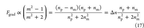
(17) Figure 1e shows how the real part of the polarizability varies depending on a particle’s refractive index,np. In this case, the
particle is assumed to be suspended in water (nm= 1.3), thus when the refractive index of the particle and the water are equal (np= nm = 1.3), the force on the particle is identically zero. Particle refractive indices less than that of the surrounding medium (for example, microbubbles21) produce a negative real part of the polarizability and, therefore, negative optical gradient force, while refractive indices greater than zero result in a positive force. Particles with a higher refractive index experience a stronger gradient force, pulling them more strongly toward the focal volume of an optical tweezers.
By using a particle with a very large real component of refractive index, the optical gradient force may be enhanced by up to several orders of magnitude. This can be achieved by choosing a dielectric material with a large polarizability22,23(see the section onantireflection coated particles) or by using a resonant system where the refractive index is maximized for a narrow range of wavelengths (see the section onmetallic nanoparticles).
However, fromeq 9, the scattering force is (to afirst order approximation) proportional to the reflectivity of the particle, which scales with (Δn)2, that is, the square of the refractive index
difference between the particle and the medium:20
∝ −
+ = Δ
+ + ⎛ ⎝ ⎜ ⎞ ⎠ ⎟ ⎛ ⎝ ⎜⎜ ⎞ ⎠ ⎟⎟ F m m n n n n n 1
2 ( ) 2
sc 2
2 2
2 p m
p2 m2 2
(18) Figure 1f shows how the scattering cross-section varies depending on the particle’s refractive index, np. It is evident that the scattering force increases more quickly with refractive index mismatch than the gradient force, thus, placing an upper limit on the maximum refractive index of a particle that may be trapped.
Imaginary Component of Refractive Index,ζ.The imaginary component of the complex refractive index,ζ, is the extinction coefficient which represents the attenuation of light within the particle. Dielectric materials are assumed to be lossless, so the absorption is negligible. In metals, however, the imaginary part of the refractive index,ζ, can be significant leading to a large imaginary component of the polarizability and hence a large absorption cross-section, defined in eq 10. This can result in significant heating of the particle. Heating can be avoided by using wavelengths in the infrared where the metal behaves similarly to a dielectric.
Particle Volume,V.From eq 1, it is clear that the optical
forces acting on a particle depend on the size of that particle. This then raises the question: what is the optimum size of a particle for trapping?
We can gain insight into this important issue by considering the simplified expression for the polarizability, valid for dipolar dielectric particles, in eq 6. Inserting this expression into the relation for the gradient force given in eq 19 gives, for small particles:
π
= ϵ −
+ ∇⟨| | ⟩ ⎛ ⎝ ⎜ ⎞ ⎠ ⎟
F r n m
The magnitude of the gradient force is proportional to the particle’s volume, ∝r3, whereris the particle radius. Nanoparticles are therefore difficult to optically trap as the gradient force may be insufficient to create a trap of sufficient depth to overcome the particle’s Brownian motion; larger particles experience a much larger gradient force than, otherwise similar, smaller particles.
However, importantly, for a particle to be trapped in an optical tweezers, the axial component of the gradient force must exceed the destabilizing effects of the scattering force. The scattering force is proportional to the scattering cross-section (eq 9), which for dipolar dielectric particles is
σ
π α
π λ
=
ϵ | | =
− +
⎛ ⎝
⎜ ⎞
⎠ ⎟ k
r m
m 6
128 3
1 2
sc 4
0
2 p2 6
5
4 2
2 2
(20) In contrast to the gradient force, the scattering cross-section is proportional tor6. Thus, the scattering force is negligible for
small particles but increases very quickly with particle size so that large particles are pushed away from the focal volume of an optical tweezers. This places an upper limit on the maximum particle size that can be trapped in any given optical trap.
To sum up, the ratio of the gradient force to the scattering force varies in inverse proportion to the volume of the particle,V:
∝ ∝
F
F r V
1 1
grad
sc 3 (21)
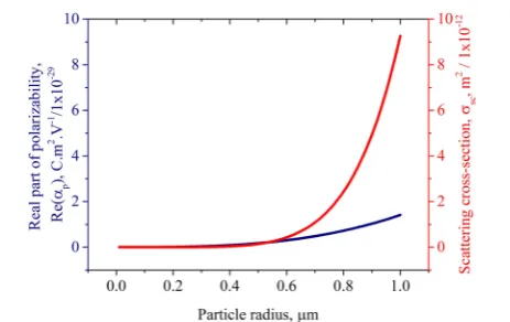
The dependence of the real part of the polarizability and the scattering cross-section on the particle size is plotted inFigure 2 for comparison.
The trap stiffness may be maximized by using a particle with radius approximately equal to the beam waist. Furthermore, this reduces the variation in measured trap stiffness which occurs due to variation in particle size between nominally identically sized beads. For applications in force measurement, choosing the appropriate particle size can improve force precision by 2.8-fold compared to using a smaller bead.24
Additionally, the absorption cross-section (eq 10) also depends crucially on particle size, thus, the laser-induced heating varies, depending on the size of particle.
■
OPTICAL TRAPPING OF HIGH REFRACTIVE INDEXAND ANTIREFLECTION COATED PARTICLES
The most obvious material parameter to play with is the refractive index of the particle. As shown earlier in the article,
the optically induced force on a particle depends directly on the relative refractive index of the particle compared to its surrounding medium: in general, the larger the refractive index difference, the larger the force. Increasing the refractive index or the size of the particle, therefore, has the potential to greatly increase the magnitude of the optical gradient force acting on the particle.
However, eqs 17 and 18 and Figure 1e,f show that the scattering force increases more quickly with particle refractive index than the gradient force. Therefore, for high refractive index particles, the scattering force dominates and particles are pushed away from the focus in the direction of light propagation, thus limiting the maximum particle refractive index that can be used. This principle can be illustrated by considering the forces acting on the most commonly used test particles in optical tweezers experiments: silica and polystyrene microspheres. The refractive index of silica is around 1.45 (atλ= 800 nm) while the refractive index of polystyrene is larger at around 1.58 at the same wavelength. The refractive index of both types of particles is substantially larger than that of water (n= 1.33,λ= 800 nm), which is typically used as a suspending medium, thus, the gradient force on both types of particles is usually sufficient to trap the particle, at least in two dimensions, given a sufficiently large intensity gradient. However, the scattering force exerted on polystyrene particles is substantially larger than that exerted on silica particles, hence, polystyrene particles can be more difficult to trap in three dimensions in a weakly focused beam. If the intensity gradient in the beam propagation direction is low (as in a weakly focused beam), then the scattering force dominates and the particles are pushed in the direction of beam propagation leading to optical guiding.25Increasing the numerical aperture of the focused beam increases the intensity gradient such that the gradient force dominates the scattering force, allowing these particles to be trapped in three dimensions in an optical tweezers. However, if the particle refractive index is even larger, not even the most tightly focused beam achievable produces a gradient force sufficient to overcome the scattering force.22,23 It was numerically demonstrated that particles with a refractive index, np, of 1.8, immersed in water, may not be trapped by a single Gaussian laser beam focused with a NA of 1.0, regardless of the particle size.22
van der Horst et al. compared the trapping forces on particles with different refractive indices in a counter-propagating optical trap.26In this geometry, two weakly diverging counter-propagating beams are used to trap a particle by balancing the radiation pressure on a particle. In this type of trap, the forces are distributed over the surface of the particle which is advantageous for stretching27or squeezing21a trapped particle; however, the total force applicable to the particle is lower than achievable using a single-beam optical tweezers geometry. In this case, however, the main advantage of this trap was that the scattering forces on the particle from each of the counter-propagating laser beams canceled, allowing high refractive index particles to be trapped. Using titanium microparticles with a refractive index of 2.4 (and diameter 1.1μm), a 3.4×larger radial trap stiffness was obtained compared to 1.4 μm diameter silica particles with refractive index 1.45. Theoretical calculations using the Mie-Debye method predicted a longitudinal trap stiffness 4×times larger for identically sized (1.1μm diameter) particles. Furthermore, a transverse trap stiffness up to 6.7×higher for titanium particles compared to silica could be achieved by removing spherical aberration.
[image:5.625.66.298.394.540.2]Although this work demonstrated the potential of high re-fractive index particles to achieve larger optical forces, in order to maximize these forces, it is desirable to be able to trap high
Figure 2.Variation of particle parameters as a function of particle size. Calculated real component of polarizability and scattering cross-section for a dipolar dielectric silica (np= 1.45,λ= 800 nm) particle, suspended
in water (nm= 1.3).
refractive index particles in a single-beam gradient force trap or optical tweezers. To achieve this, high index particles can be coated with a thin layer to reduce the reflectivity, thereby reducing the optical scattering force acting on the particle.
Antireflection coatings are commonly used on the surfaces of lenses and other optics to reduce reflections and increase the amount of transmitted light. Coatings consist of one or more transparent thinfilms with thickness chosen such that beams reflected from each interface interfere destructively and trans-mitted beams interfere constructively.28
The simplest type of antireflection coating consists of a single layer of a material with refractive index,nl, between that of the
particle and surrounding medium (typically water):nm<nl<np, where nl = n nm p. This replaces the single water−particle interface with two interfaces: a water-coating interface, Δn1 = nl − nm, and a coating-particle core interface, Δn2= np − nl.
Because the coating has a refractive index lying between those of the particle and water, the reflection at each of these interfaces is less than that at the particle−water interface. In fact, since the Fresnel equations stipulate that the reflectivity is proportional to the square of the refractive index difference, (Δn)2, and because
the sum of the squares is less than the square of the sum, the total sum of the reflectivities, (Δn1)2+ (Δn2)2, at the two interfaces is
less than that at the particle−water interface:
− + − < −
Δ + Δ < Δ
n n n n n n
n n n
( ) ( ) ( )
( ) ( ) ( )
l m 2 p l 2 p m 2
1 2
2 2
T 2
(22) Thus, the reflectivity and, hence, the scattering force on a high index particle can be reduced by coating the particle in a thin layer of a material with refractive index equal to the geometric mean of the core of the particle and the surrounding medium.
Indeed, coating polystyrene particles with a thin layer of silica results in more than a 2-fold increase in the trap stiffness, compared to homogeneous polystyrene or silica particles.20 In this example, polystyrene spheres with diameters ranging from 1.3−1.8μm were coated with an approximately 200 nm thick layer of silica in order to reduce the scattering force.20
Mie calculations have shown that adding an antireflective coating to particles increases the trap stiffness in an optical tweezers sufficiently to allow high refractive index particles to be trapped which would otherwise be unable to be trapped. Furthermore, particles with high core refractive index benefit even more from the coating than lower refractive index particles.22
High refractive index particles of titania with a refractive index, np, of 2.3 have been coated with an antireflective shell, which enabled them to be trapped in a single-beam optical tweezers.23 The high refractive index of the core produced high gradient forces in excess of a nanonewton, an enormous increase of up to 3 orders of magnitude compared to the usual force in optical tweezers, which is typically sub-pN to 100 pN.
The use of antireflection coated high refractive index particles can be used to enhance existing optical trapping setups, providing a large dynamic range from sub-pN to nN forces and bringing photonic force microscopy into the sensitivity range of tech-niques such as atomic force microscopy (AFM). This presents new possibilities for optical trapping and photonic force microscopy. Furthermore, since the same optical force can be achieved using a much lower laser power, these particles are ideal for experiments using living biological organisms, as laser-induced photodamage can be significantly reduced.20,23
Antireflection coated particles have been used to make measurements of kinesin motors under forces of up to 100 pN.20The use of coated beads allows lower powers to be used, a larger linear distance range in detection, and better resolution measurements20to be obtained, compared to previous measurements.29
Antireflection coated, high refractive index particles may also be used to enhance the optical forces applied to biological cells in an optical tweezers. Since the refractive index mismatch between a cell and its surrounding medium is generally small, the forces applied to a cell can be enhanced by attaching a microsphere which acts as an optical handle. Antireflection coated titania microparticles have been incubated with cell lines so that the particles endocytosed.30 Drag force measurements31 revealed that cells incubated with antireflection coated microparticles demonstrated an increase in the trap efficiency,Q, of 45% com-pared to those incubated with uncoated polystyrene particles, and nearly 220% compared to untagged cells. (The trapping efficiency, Q, is a nondimensional parameter, which is defined asF= Qn P
c
m
, whereFis the optical force exerted on the particle, nmis the refractive index of the surrounding medium, andPis the power of the incident beam.) Furthermore, the antireflection coated particles enabled high cell velocities of 50 μm/s to be achieved using only 33 mW of laser trapping power.
Looking to the future, the ability to achieve nanonewton forces with subpiconewton resolution opens up the possibility to explore new cellular biology with optical tweezers. Mechanical characterization of macromolecules, or more complex cellular processes such as protein unfolding,32amyloidfibril disruption,33 and cell adhesion and contraction forces34may all require nano-newton force capabilities which are beyond the capacity of a standard optical trap.23An optical tweezers equipped with anti-reflection coated particles could be used to complement atomic force microscopy approaches, while taking advantage of the three-dimensional capabilities of optical trapping, which may be particularly useful when investigating biological samples.23
In addition to increasing the stiffness,κ, of an optical trap, the use of antireflection coated particles also increases the natural resonance frequency of the trap:
κ
Ω =
m (23)
where m is the particle’s mass. As described above, the trap stiffness,κ, can be greatly increased by using an effective anti-reflection coating. A challenge for the future will be the fabrica-tion of small, low mass, antireflection coated particles which would further maximize the natural trap oscillation frequency.
Theoretical calculations of the normalized trap stiffness as a function of particle size are reproduced from the work of Jannasch et al.23inFigure 3. The plots show islands of stability and regions (marked white) corresponding to particle dimensions that cannot be trapped. Particularly of note is the absence of trappable particles in the bottom left-hand corner of the plots, indicating that small antireflective particles with total diameter less than around 1μm would be difficult to trap, due to insufficient shell thickness to result in destructive interference of the light reflected from the outside of the particle and the core− shell boundary at this given wavelength. Much shorter trapping wavelengths may assist in reaching smaller size regions for AR particles, though care would need to be taken with photodamage for their use in biological studies.
Figure 4shows the size distribution of antireflection coated particles, reproduced from the work of Craig et al.30The histogram shows a size distribution peaking at the 801−900 nm size range, with a fairly wide distribution of particle sizes. Both reducing the mean particle size and improving the size homogeneity of antireflection coated particles would be beneficial. Extending the range of antireflection coated probes to the nanoparticle size regime would open up new avenues of research in situations where a high natural oscillation frequency is a key advantage.
One such application would be in the burgeoning area of levitated optomechanics. Trapping a particle in vacuum instead of liquid greatly reduces viscous damping, allowing physics at the classical-quantum boundary to be probed. However, detection of many interesting quantum effects relies on being able to cool a trapped particle toward the quantum ground state. In order to observe quantum effects on a particle, the mean thermal occupancy, n = ℏΩk TB must be less than unity. Maximizing the
[image:7.625.71.553.439.620.2]natural oscillation frequency, Ω, both by increasing the trap
Figure 4.Figure reproduced from Craig et al.30ACS Copyright 2015. Size distribution of antireflection coated microparticles and a scanning electron microscope image of such a particle.
Figure 3.Trap stiffness calculations of antireflection coated particles of various sizes. Figure reproduced from Jannasch et al.23ACS Copyright 2012. Mie theory predictions of lateral (top row) and axial (bottom row) trap stiffness per power in the focus as a function of core diameter and total coreshell diameter. White areas correspond to particles that cannot be trapped. The black line demarcates zero shell thickness. (a, c) T-matrix calculations based on the optical tweezers toolbox. The symbols indicate the size of the fabricated titania coreshell particles. (b, d) Calculations including spherical aberrations. The geometric focus of the trap is 5μm away from the glass surface.
stiffness,κ(via antireflection coatings) and reducing the mass,m, of the trapped particle, may help to produce a probe sufficiently sensitive for the detection and measurement of new quantum physics.
Moreover, the ability to fabricate smaller antireflection coated particles would be advantageous for biological studies of intra-cellular processes, where smaller particles would facilitate more precise tagging of intracellular components such as proteins or macromolecules. Functionalizing antireflection coated particles with biotin−streptavidin complexes would also be advantageous for future biological studies using these particles.
The enhanced trapping forces achievable by modifying the material properties of particles, such as increasing the refractive index of the particle core and reducing the scattering force via coatings, may be fully exploited by combining these particles with optical systems that take advantage of certain optical proper-ties of the lightfield. For example, reducing the wavelength of the optical trapping beam can greatly increase the stiffness,κ, of an optical trap, as15
κ λ
∝ 14
(24) However, changing the wavelength may also influence the laser-induced heating of the particle, thus, the absorption cross-section must also be considered when choosing an appropriate wavelength.
Furthermore, wavefront distortions are a major problem in optical tweezers. In particular, spherical aberration caused by the refractive index mismatch at the sample is a common reason for reduction in the axial trap strength. However, spherical aberration can be compensated by careful choice of the refractive index of the immersion media, allowing more than a 2-fold increase in axial trapping strengths.35Furthermore, by changing the refractive index of the immersion media, spherical aberration can be compensated at a range of depths, allowing trapping deep within samples.35
Aberration compensation can be extended to other aberrations by using dynamic diffractive optics to apply wavefront correc-tions in situ.36This allows the focusing of the laser beam to be optimized for trapping, even through highly turbid and diffusive media, with extremely low powers of a fraction of a milliwatt.36 Combining wavefront correction with high index, antireflective, particles presents new opportunities for trapping in colloidal and biological physics.
A recent work has shown that the trap stiffness may be even further enhanced by shaping inputfields for the spatial struc-ture of scattering to improve trap stiffness. This can lead to a 27.5×higher trap stiffness compared to a Gaussian trap37and a dramatic improvement in the measurement signal-to-noise ratio observed in experiments. This method is presently applicable in one dimension only and is applicable for larger particle sizes due to the inherent reliance on interference. This approach may be amenable to vacuum trapping studies where large volume (mass) particle may probe gravitational effects, or studies in hydro-dynamics where larger particles may couple more strongly to
fluidflow.
■
OPTICAL TRAPPING OF METALLICNANOPARTICLES
Dielectric nanoparticles are generally more challenging to trap compared to larger particles due to the volume scaling of the polarizability and subsequent optical gradient forces, discussed in the section on particle size. Fromeq 19, it is clear that the
gradient force varies in proportion to the particle volume: Fgrad∝r3. Indeed, reducing the particle radius from 1μm to 100 nm,
or from 100 to 10 nm, reduces the maximum optical trapping force by 3 orders of magnitude each time.
However, if the material of the nanoparticle is a metal, the refractive index, np, and polarizability, αp, of the particle are
strongly wavelength-dependent and are especially enhanced for a narrow range of wavelengths due to unique optical properties originating due to resonances in the light scattered by the particle. This can result in substantial enhancement of the optical forces for certain wavelengths, allowing trapping of small metallic nanoparticles which would otherwise be impossible due to their small size.38−40A comprehensive review of this subject can be found in the work of Lehmuskero et al.41,42
Gold particles with a radius of 50 nm have been trapped with a 6-fold enhancement in trapping efficiency compared to similar-sized polystyrene particles43and, using different trap parameters, smaller particles with radius 18 nm have been shown to offer a 7-fold improvement.44Furthermore, metallic particles may be trapped at a lower laser power than dielectric particles.44
The resonances in the optical properties of metallic particles, called “plasmon resonances”, occur due to resonances in the induced oscillatory motion of electrons in the metal in response to the applied electric field of the laser beam. The electron dynamics in the metal are described classically by the Lorentz− Drude model45where a free electron gas is free to move between relatively immobile ions. In response to an applied electric
field, E(t) = E0 exp(−iωt), the electrons experience a force
and undergo oscillatory motion,x(t) =x0exp(−iωt), obeying the equation of motion:
γ
∂ ∂ +
∂ ∂ = −
m x
t m
x
t eE
e 2
2 e e (25)
wheremeis the electron mass,eis the electron charge, andγeis
the collisional damping frequency due to collision and scattering events. Solving the equation of motion gives the dielectric function:
ω ω
ω γ ω
ϵ = − +i
( ) 1 p
2
2 e (26)
wherendis the number density of the electrons and
ω =
ϵ
n e m
p d
2
e 0 (27)
is the plasmon frequency of the free electron gas.
From eq 26, it is evident that for frequencies below the plasmon frequency, that is,ω < ωp, the dielectric function is
negative, and therefore, the refractive index,n*, is imaginary. At these low frequencies, the free electrons in the metal are able to move sufficiently fast to shield the electricfield, preventing light from propagating through the material. The light is therefore reflected and absorbed. In this long wavelength regime, optical forces may be enhanced due to this free electron contribution to the polarizability. However, as explained in the section on refractive index, the large absorption cross-section (defined in eq 10) can lead to significant heating of the particle, increasing its Brownian motion and making it more difficult to trap.
At frequencies higher than the plasmon frequency, that is, ω>ωp, the electrons are unable to oscillate fast enough to shield
the field, hence, the material becomes transparent. At this wavelength range, the absorption is less and the material behaves
more similarly to a dielectric. The polarizability is largely real, with the size and sign of the real component determining the magnitude and direction of the optical gradient force, respectively.
The optical properties of a metallic particle can be calculated usingfitting parameters.46,47The real and imaginary components of the polarizability of a 40 nm diameter Ag nanoparticle, in addition to the absorption and scattering cross sections, are shown inFigure 5.
[image:9.625.137.488.68.324.2]Real Part of Polarizability and Effect on Gradient Force.
Figure 5a shows the real part of the polarizability, for a 40 nm diameter silver nanoparticle, which has a strong resonance centered on the plasmon wavelength. The resonance in the polarizability can be directly exploited to provide enhanced forces at specific wavelengths. Since the gradient force is proportional to the real part of the polarizability (see eq 19), the gradient force acting on a metallic particle can be maximized by tuning the wavelength to match the peak in the real part of the polarizability (in this case around 425 nm), close to the plasmon resonance.
Both gold38,44,48and silver nanoparticles39have been trapped in three dimensions. However, the choice of metal strongly affects the optical forces achievable. For example, gold absorbs more than silver and therefore the plasmon resonance of gold nanoparticles is strongly damped.48 This means that the real part of the polarizability of spherical gold nanoparticles is always positive resulting in an attractive gradient force for all wave-lengths. In contrast, for silver nanoparticles, the real part of the polarizability may be negative for excitation wavelengths shorter than the plasmon wavelength,40 as shown in the example in Figure 5a. By tuning the wavelength fromλ>λptoλ<λp, the
gradient force may be reversed from attractive to repulsive. This wavelength dependence of the direction of the gradient force presents opportunities for the optical selection of metal nanoparticles with particular properties. Furthermore, by balancing
competing gradient forces from red- and blue-detuned fields, a stable trap for Ag nanoparticles can be created, the location of which depends on the particle properties.46This is similar to an analogous scheme for optical trapping of cold atoms which uses the atomic resonance in place of the plasmon resonance.49
Imaginary Component of Polarizability and Effect on
Scattering Force, Absorption, and Heating.The imaginary
component of the polarizability also contains a strong resonance, as plotted inFigure 5b, therefore, the absorption and scattering cross sections, defined ineqs 10and9and plotted inFigure 5c,d are also resonant parameters.
The resonant peak in the imaginary component of the polarizability is blue-shifted with respect to the peak in the real part, as defined by the Kramers-Krönig relation,50thus, the wavelength can be tuned to maximize the gradient force acting on a particle while reducing the destabilizing scattering force. Conversely, by blue-detuning the beam, scattering forces can be optimized for particle manipulation. Scattering forces using a blue-detuned laser beam have been used to confine Au nano-particles within the dark core of a donut-shaped lightfield in an optical tweezers.48
The resonance in the optical scattering force can be used to optically sort two types of gold nanoparticles with different plasmon wavelengths due to their differing size.51Larger particles with diameters of 150 and 130 nm were driven in one direction while smaller particles with a diameter of 100 nm have been pushed in the opposite direction by a second beam with a different wavelength.51
However, tuning the wavelength to access the strong resonant enhancement of the scattering force comes at the expense of increased heating of the trapped particle. The large absorption cross-section,σabs, which is maximized at the resonant peak of
the imaginary component of the polarizability, leads to dramatic heating in metallic particles which can cause damage to biological samples, incorrect calibration of the trap stiffness, and ultimately
Figure 5.Optical properties of a 40 nm diameter spherical silver nanoparticle as a function of wavelength calculated from the Lorentz−Drude model:46 (a) real part of the polarizability, Re(αp); (b) imaginary part of the polarizability, Im(αp); (c) absorption cross-section,σabs; (d) scattering
cross-section,σsc.
destabilize a particle from the trap. Trapped gold beads with radii of 50 nm were shown to cause a dramatic rise in temperature of 266°C per W of laser power,43more than 20×higher than the laser-induced heating of water.52 Therefore, caution must be applied when using metal nanoparticles as handles for manipula-tion of biological samples. Even at a low power resulting in a trap stiffness of only 12 fN/nm, the local temperature increase of 55°C is sufficient to damage certain biomaterials such as enzymes.43
However, in certain applications, the localized heating around a metal nanoparticle could be exploited to create a nanosource of heat53for chemical and metabolic thermal activation.54
Effect of the Dimensions of a Metal Nanoparticle on
the Optical Forces.In addition to the influence of the material
(choice of metal) on the plasmonic properties of a nanoparticle, the optical properties such as polarizability and the resultant cross sections are determined by resonances that can be tuned by changing the particle’s size, shape, or aggregation. Increasing the size of a metallic nanoparticle red-shifts the plasmon resonance wavelength. Exploiting this allows spherical nanoparticles with different sizes to be optically sorted by tuning the wavelength to the plasmon wavelength of the relevant particle type.51
Moving beyond the simpler case of spherical nanoparticles, metallic nanoparticles of various shapes and composition can be stably trapped, including nanorods, nanowires, Au/Ag core/shell nanorods, and Au bipyramids.55 For more complex particle geometries, not only the particle size, but also the aspect ratios become important.
Nanorods are nanocylinders with each dimension within the range 1−100 nm and an aspect ratio of less than 10. In metallic nanorods, two main plasmon modes are excited corresponding to the longitudinal and transverse dimensions. The longitudinal plasmon mode of these anisotropic particles is used to enhance the gradient force and increase the depth of the trap potential, allowing single gold nanorods to be trapped for several minutes.56 But tailoring the aspect ratio of metallic nanorods allows for even greater control over the plasmon wavelengths and, subsequently, the enhancement of optical forces and torques. For example, although the real part of the polarizability for spherical gold nanoparticles is always positive, increasing the aspect ratio of the gold nanoparticles can result in negative values of the real part of the polarizability for a certain blue-detuned range of wavelengths. This causes reversal of the optical gradient force, causing the gold nanorods to be repulsed from the laser focus.56
In addition to optical forces, elongated particles present possibilities for inducing optical torques and rotation of trapped particles.57Elongated metallic nanostructures usually self-align in an optical trap with their long axis parallel to the electricfield vector of the trapping laser and orthogonal to the beam pro-pagation axis due to their high long-axis dipole polarizability.56 The orientation of the nanorods can thus be controlled by rotating the laser polarization.58,59The strength of the aligning torque may be maximized by tuning the laser wavelength close to the plasmon resonance. A single gold nanorod can be used to exert optical torques up to 100 pN nm in a linearly polarized optical trap.60This is sufficiently large to address single molecule processes in soft and biological matter.
Even more elongated particles such as nanowires (elongated particles with an aspect ratio greater than 10) may also be optically trapped. Individual metallic nanowires with lengths from tens of nanometers to several micrometers have been trapped in a linearly polarized beam.59Interestingly, the angle of alignment of the particles depends on their length. While silver nanorods align parallel to the laser polarization due to the high
polarizability along the long axis, longer silver nanowires align perpendicular to the laser polarization vector. In both cases, the use of circularly polarized light causes the particles to spin due to the rapidly rotating polarization vector and the transfer of spin angular momentum from the beam to the particles due to their anisotropy.59
As is the case for spherical particles and nanorods, the choice of metal is crucial for nanowires in order to optimize the optical forces for the application. For example, individual gold nanowires with lengths over 2 μm are able to be trapped in an optical tweezers, whereas silver nanowires with a similar length and diameter cannot be trapped in three dimensions by the same Gaussian beam due to their high scattering and absorption cross sections.61
However, by tailoring the optical fields to the shape of the particle, forces on silver nanowires can be optimized allowing them to be trapped. By creating an extended focal region by focusing a Bessel beam and combining this with a retroreflection geometry to cancel the radiation pressure force, highly scattering and absorbing silver nanowires are able to be trapped. Using this geometry, individual silver nanowires with lengths of several micrometers may be positioned with a precision better than 100 nm and can be oriented with an angular precision of 1°.62
Developing the concept of shaping the lightfield to the particle geometry further, shaping the laser beam into a tailored optical landscape allows for multiple nanowires to be simultaneously trapped in separate maxima of thefield. Since trapping of nano-wires in an interferometric optical landscape is robust and allows trapping near surfaces, this technique enables the controlled assembly of nanowires into plasmonic nanostructures.62Using a spatial light modulator to produce optical gratings and Bessel light fields, optically trapped nanowires can be controllably positioned and oriented on a dielectric substrate, facilitating the noncontact assembly of plasmonic nanostructures for particular functions.63
In addition to spherical and elongated particles, other more exotic metallic nanoparticle shapes have been trapped. Shaping gold nanoparticles into nanoprisms can result in an increase in the trap stiffness of an order of magnitude as the destabilizing scattering force is reduced. Nanoprisms with sizes between 20 and 250 nm have been trapped at extremely low numerical apertures of between 0.2 and 0.37, indicating that larger metallic particles do not always behave as highly reflective mirrors, as was previously believed.64Plasmon-enhanced optical forces can also be used to trap gold nanoaggregates with selected structural and optical properties.65
On the other hand, the isolated, noncontact, nature of optical trapping provides a suitable platform to investigate material properties of nanoparticles. Ultrafast pump−probe spectroscopy can be combined with optical trapping to measure the damping of acoustic vibrations within gold nanospheres and nanorods.66 The technique and results pave the way for further study of mechanical dissipation in metals at frequencies of 1−1000 GHz, a range that is otherwise difficult to access.
In addition to the application of optical forces for manipulation of nanoparticles, optical forces may be combined with spectro-scopic techniques to interrogate chemical and physical properties of the trapped materials with applications for nanoscience and biology.67,68The use of metallic structures, which may be either nanopore structures or trapped metallic nanoparticles, can enhance the opticalfields via the plasmon resonance, enhancing both the optical trapping forces and the (typically Raman) spectrum.
■
OPTICAL TRAPPING OF NANOMATERIALSNanomaterials are materials which have at least one dimension on the nanoscale, sometimes defined as between 1 and 1000 nm, or more usually between 1 and 100 nm.69 Although optical trapping has successfully been applied for a number of years to the manipulation of both larger particles (e.g., microspheres and cells) and smaller particles (e.g., the cooling of atoms, ions, and molecules), optical manipulation of the intermediate nanoscale size regime has been limited until recently. This size regime includes quantum dots, nanowires, nanotubes, graphene, and two-dimensional crystals: structures that form the basis of a number of emergent areas of optical and materials research.
Compared to microparticles, nanoparticles are able to be trapped in weaker potentials with greater Brownian motion
fluctuations. Due to the increased sensitivity, nanoparticles, there-fore, present opportunities for ultrasensitive potential sensors or as force transducers which may have applications for localizing matter at the nanoscale, for measuring thermophoretic effects,70 or for investigating molecular motors.32
This section discusses recent advances in the optical trapping of nanostructures (other than metallic nanoparticles, which are discussed in a separate section). A more comprehensive review of the subject may be found in the review by Maragòet al.71
Nanostructures may be conveniently grouped according to the number of nanoscale dimensions. Nanowires are considered one-dimensional nanostructures due to their small width. Semiconductor nanowires, which have widths tunable from 2 to 200 nm and lengths spanning from hundreds of nanometers to millimeters,72are of widespread interest due to their potential as building blocks for miniature electrical,73 nanofluidic,74 or optical75devices. A photonic platform using nanowires would
offer advanced photonic capabilities at dimensions compatible with on-chip technologies.72Although methods for the growth and fabrication of semiconductor nanowires are well-established, progress toward such devices has been slow due to a lack of methods for their manipulation and assembly. Optical manip-ulation offers a convenient approach to trap and assemble semiconductor nanowires into arbitrary structures with high spatial and angular precision.76
A range of inorganic nanowires including GaN, SnO2, ZnO,
and Si nanowires, with diameters as small as 20 nm and aspect ratios of more than 100, have been optically trapped in an optical tweezers.76 Using optical forces, the nanowires can be trans-ported at velocities up to 10μm s−1and arranged in nanowire architectures that can function as active photonic devices.76Once the nanowires are in position, a second focused laser can be used to anneal the ends of each nanowire to stabilize the circuit and reduce the circuit resistance, as has been demonstrated with In2O3nanowires.
77
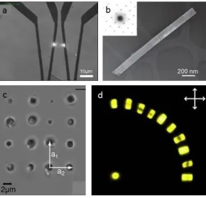
[image:11.625.168.459.68.347.2]A completed junction is shown inFigure 6a. Trapped potassium niobate (KNbO3) nanowires, as shown in Figure 6b can be used as an electrode-free, continuously tunable coherent visible light source. The wires act as frequency con-verters via second harmonic generation, allowing a wide range of colors to be produced in the wire. This tunable nanometric light source can be used for a novel form of subwavelength microscopy in which a laser is used to trap and scan a nanowire over a surface, with a range of potential applications in physics, chemistry, materials science, and biology.78
Importantly, the manipulation of semiconductor nanowires is compatible with biological environments, so the above technique can be applied to high resolutionfluorescence imaging of bio-logical samples.78Moreover, nanowires may be assembled in
Figure 6.Optically trapped nanomaterials. (a) Optically trapped In2O3nanowire which has been manipulated to form a junction. Adapted with
permission from the work of Lee et al.77OSA Copyright 2011. (b) Transmission electron microscope image of a KNbO3nanowire and its electron
diffraction pattern (inset). Adapted with permission from the work of Nakayama et al.78NPG Copyright 2007. (c) Rectangular lattice of three dimensionally trapped zeolite L crystals ordered by size. Adapted from the work of Woerdemann et al.79Wiley Copyright 2010. (d) Structure of 11 dye-loaded zeolites on a glass surface. Adapted from the work of Veiga-Gutierrez et al.80NPG Copyright 2012.
physiological environments, offering the potential for chemical, mechanical, and optical stimulation of living cells.76
The anisotropy of semiconductor nanowires can lead to enhanced optical forces. Silicon nanowires have been trapped and rotated in high vacuum. Their anisotropy leads to optical forces that are three times stronger than those on silicon nano-spheres of the same mass.81
Two-dimensional materials such as grapheneflakes may also be trapped in an optical tweezers and their dynamics analyzed by Brownian motion.82In addition to graphene, the ability to trap two-dimensional nanostructures provides opportunities for optical manipulation and sorting of biological membranes and anisotropic macromolecules.82
Carbon nanotubes can be considered to be sheets of graphene rolled up to form a cylinder. The diameter of the nanotube is typically a few nm and determines the frequencies of optical resonances in the nanotubes called radial breathing modes. By tuning the laser wavelength to these frequencies, nanotubes with certain diameters may be optically addressed. Selective aggregation of single-walled carbon nanotubes by the optical gradient force has been demonstrated in an optical tweezers.83 Furthermore, the resonant optical scattering force has been used to achieve enrichment of four different diameters of single-walled carbon nanotubes.84This demonstrates the feasibility of using resonant optical forces for all-optical sorting of carbon nano-tubes, allowing separation of nanotubes with very different optical and electronic properties, which is vital for the develop-ment of carbon electronics.85 Moreover, elongated bundles of carbon nanotube aggregates have been trapped in an optical tweezers and shown to rotate around the optical axis. This behavior may be useful for the creation of rotating nanomachines.58
Colloidal quantum dots are crystals of semiconductor material with diameter on the order of several nanometers. The small size of the colloid results in the electrons experiencing strong quantum confinement and, as a result, the electronic and optical properties are closely related to the size and shape of the quantum dot. The emission and absorption spectra are highly tunable, and their luminescent and bleaching properties make them of interest asfluorescent markers in nanoscale materials and biological samples.86,87
Quantum dots may be used both for imaging and as a handle for controlled manipulation. Pulsed high power lasers have been used to optically trap aggregates of quantum dots88and single quantum dots have been trapped using continuous wave optical tweezers.89,90Individual quantum dots may be simultaneously trapped and excited by two-photon absorption using the same continuous wave IR laser, thus eliminating the requirement for an additional excitation light source in nanoscale experiments.91 Since a quantum dot is much smaller than a diffraction limited focus, a trapped and excited quantum dot can be used to map out a focal volume, showing areas where the intensity of thefield is too low to cause two-photon absorption.92
Upconverting fluorescent nanoparticles, fluorescent nano-particles which sequentially absorb two or more photons and emit light with a shorter wavelength, may also be trapped with applications for precise fluorescence sensing in biophotonics experiments.93Dielectric NaYF4: Er3+, Yb
3+nanoparticles with
diameters of around 26 nm have been trapped using a continuous wave 980 nm laser, with the same laser used to excite visible luminescence from the trapped nanoparticles.
Trapping of nanomaterials is not limited to metals and semi-conductors. Zeolite L is a porous material featuring parallel, one-dimensional and hexagonally arranged channels.79When the
channels are loaded with organic dyes, metal clusters, or complexes, they exhibit interesting optical properties. As a result, zeolite L is of significant interest for a wide range of applications, including as luminescent labels for imaging94 or for light harvesting antenna materials.95 Zeolite L crystals may be organized and patterned in three dimensions using a holographic optical tweezers,79 as shown in Figure 6c. By assembling structures of zeolite L with small molecules lodged within their nanopores (as shown inFigure 6d), zeolites are able to bridge the gap between the micro- and nanoworlds.80Using an optical tweezers assembly line, different assemblies of zeolite L structures can be achieved, including monolayers, microtowers, and angle-aligned dye-loaded zeolites, which may prove useful as microscopic polarization sensors.80
■
OPTICAL FORCES ON BIREFRINGENT AND CHIRALPARTICLES
In addition to the linear momentum required to generate optical forces, light can also carry angular momentum which may be harnessed to apply optical torques on trapped objects. The angular momentum is a vector quantity that expresses the rotation present in the electromagneticfield. For any classical system, the density of angular momentum is given byj(r) =r× p(r), in terms of p, the momentum density. In the paraxial approximation, the total angular momentum,J=jdris separated into two terms: an orbital part,L, and a spin part,S:J=L+S. The orbital part,L=R×Pis the angular momentum associated with the center-of-mass motion, withP=∫pdrthe total momentum. The orbital angular momentum,Lcan always be made to vanish by an appropriate choice of origin. The spin part,S, is the angular momentum in the center-of-mass system, corresponding to the rotation of an object about its center of mass.96
The orbital angular momentum component,L, arises due to the spatial distribution of a light beam. While a Gaussian laser beam has spherical wavefronts, certain types of beams which include azimuthal phase terms, exhibit wavefronts which are helical or twisted and inclined with respect to the optical axis. In these cases, the Poynting vector, = × *
μ S 1E B
0
, which represents the direction of energyflow, spirals around the optical axis. Such beams include Laguerre-Gauss,97 Bessel beams,98 Mathieu beams,99 and Ince-Gaussian beams.100 The orbital angular momentum transferred to the particle is independent of the photon energy and is equal to±lℏper photon, wherelis the integer multiplier of the azimuthal phase term, eilϕ, which quantifies the pitch of the phase ramp about the beam axis.
In contrast, the spin angular momentum arises due to the polarization of the light field, with the direction determined by the handedness of circular polarization. The spin angular momentum transferred to the particle is±ℏper photon.
Just as the linear momentum may be visualized by observing its interaction via the scattering or gradient force with an absorbing or scattering object, the same applies to the angular momentum. The spiraling Poynting vector of a beam carrying orbital angular momentum exerts a torque on a particle, causing it to orbit around the beam axis. Spin angular momentum, on the hand, causes a particle to rotate around the particle’s own axis.
While orbital angular momentum can be readily transferred from an appropriate beam to any particle with a significant absorption or scattering cross-section, the transfer of spin angular momentum from a circularly polarized beam to a particle depends on the particle material. For spin angular momentum to be transferred to a particle, the particle must be optically
anisotropic, meaning that the polarizability and hence the refractive index depends on the polarization and propagation direction of the light. Among other materials, including stretched plastics and asymmetrically shaped nanostructures such as the nanorods and nanowires discussed in the sections on metallic nanoparticles and nanomaterials, this is the case in crystals with asymmetric crystal structures, which are termed birefrin-gent. The amount of birefringence is quantified by the magnitude of the difference between refractive indices along orthogonal axes:Δn=ne−n0.
Birefringent crystals are more commonly known for their use in retarders such as half- and quarter-wave plates. These optical elements work due to the accumulated phase difference
ϕ
Δ = 2λπd n(| 0− ne|)
0 between orthogonal polarization
compo-nents, wheredis the thickness of the crystal andλ0is the optical
wavelength in vacuum. The state of polarization of the emergent light depends on the amplitudes of the incoming orthogonalfield components and onΔϕ. A half wave plate introduces a phase shift,Δϕ, ofπbetween the orthogonal o- and e- axes, which acts to rotate the polarization vector through an angle of 2Δϕ, converting an incident +σcircularly polarized beam to a circularly polarized beam of opposite handedness,−σ.28
The rotation of the polarization vector arises due to a transfer of angular momentum from the half wave plate to the beam. An equal and opposite transfer of angular momentum is transferred from the beam to the half wave plate, as was observed for thefirst time in 1936 using an extremely sensitive torsion pendulum.101 For most half wave plates, the inertia is far too large for this miniscule effect to be observed. However, reducing the size of the half wave plate to that of micron-sized particles or smaller increases the rate of rotation dramatically. A birefringent particle, made of, for example, calcite, optically trapped in a circularly polarized beam, acts as a miniature half wave plate and therefore experiences the same transfer of spin angular momentum. This induces rotational motion, causing the particle to spin about its axis at rotation rates of over 350 Hz.102 By measuring the rotational velocity of the particle, the torque can be calculated and used to infer the viscosity of the surrounding medium, either in liquid103or a gaseous media.104A rotating birefringent microsphere optically trapped in liquid generates a localized microfluidicflow which exerts a shear stress on nearby objects and can be used to direct the direction of an axonal growth cone for the control of nervefiber growth.105
[image:13.625.139.493.70.224.2]Optical rotation of birefringent microparticles also offers advantages in the rapidly emerging area of optomechanics. The greatly reduced viscosity when trapping in vacuum instead of liquid allows rotation rates of up to 10 MHz to be achieved.106 Figure 7a−d shows images of birefringent vaterite (calcium carbonate) particles used to achieve these rotation rates. Figure 7e shows the particle rotation rates as a function of pressure. Gyroscopic stabilization resulting from the fast rotation can be used to increase the trap stiffness and cool the motion of a trapped particle106in a similar way as when the anisotropy of silicon nanorods is exploited to achieve rotation.81The increased control over the particle’s position and associated degrees of freedom is invaluable in order to move toward exploring theoretical predictions such as the Casimir force and quantum friction.107,108
In addition to particles made of birefringent crystals, elongated particles, such as nanorods and nanowires, made of optically isotropic materials may be birefringent due to their shape.59
Whereas birefringent particles exhibit an anisotropy between the fast and slow axes, chiral particles contain a material anisotropy, such that they cannot be superposed on to their mirror image. This anisotropy may be present at the micro- or nanoscale, for example, a gold helix,109or it may occur at the molecular level, as is the case with liquid crystal droplets.110
A particle’s chirality is only manifested when it interacts with another chiral entity, for example, a circularly polarized electromagnetic wave. Left- and right-circularly polarized waves exhibit opposite chirality and therefore interact differently with a chiral particle, which can lead to completely different, or even oppositely directed, optical forces, depending on the handedness of the polarization.
Chiral forces can be used to optically trap and rotate poly-merized microdroplets containing liquid crystals.111The liquid crystal molecules form an onion shell structure which allows the particle to function as an omnidirectional chiral mirror. This system provides an ideal playground to examine the coupling of linear and angular momentum and allowsfine-tuning of chirality-induced forces and torques.
Furthermore, oriented trapping of plasmonic gold nano-particles by topological singularities in nematic liquid crystals was demonstrated, producing large trap stiffnesses that depend on the shape and size of trapped nanocolloids.112
In addition to optical torque, chiral material properties may interact with a light field to produce additional linear optical
Figure 7.Figure reproduced with permission from Arita et al.106NPG Copyright 2013. (a−d) Scanning electron microscope images of birefringent vaterite particles. (e) Particle rotation rates as a function of pressure showing rotation rates in excess of 1 MHz. The inset shows the power spectral density at a rotation rate of 2.45 MHz at a pressure of 1 Pa.