Modelling of a Bio-Inspired Knee Joint and Design of an Energy Saving
Exoskeleton Based on Performance Maps Optimisation for Condylar Knee
Prosthetics
Appolinaire C. Etoundi, JJ Chong and Aghil Jafari ,
Member, IEEE
Abstract— The process of designing bio-inspired knee joint for prosthetics/exoskeletons has been a challenging issue due to the complicated relationships between the performance criteria and the link lengths of the design space, or workspace in the case of manipulators. This paper address this issue by presenting numerical analysis and design methodology that have been used for mapping the design space of a bio-inspired knee joint. Four aspects of performance are modelled: peak mechanical advantage, RMS (root mean square) mechanical advantage, RMS sliding ratio, and range of movement. The performance of the joint is dependent on the shape of the condylar surfaces and the geometry of the four-bar mechanism. The results of the complete map for the design space are characterized by the mechanical advantage, sliding ratio and the range of movement that mimics the human knee joint with the movement of rolling and sliding between the condylar surfaces of the femur and tibia. Therefore, several design charts are proposed accordingly to facilitate the selection of designers of the optimal configuration adapted to their specific application. Based on our numerical analysis performed on the proposed bio-inspired knee joint model, the performance maps demonstrated that there is an estimated reduction of 30% for the actuator required force.
I. INTRODUCTION
A. Biomechanics for the Human Knee Joint
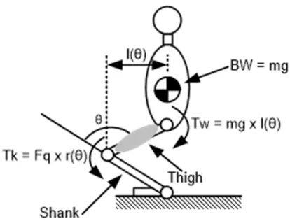
The force required at the knee to support standing depends on the angle of the knee. Thus, to go from a standing to a squatting position, the quadriceps force must produce a required amount of force to counteract the torque created by the body weight and the distance from the centre of the body. The schematic in Fig. 1 shows the force vectors that interact during squatting movements to balance the knee while it flexes.
These torques are the result of the two main actions of the body during flexion/extension. The first one is notedTw,
as the body mass drops vertically the distance to the knee increases. The other torque is the required quadriceps force multiplied by the moment arm at the knee (Tk). This is the
counterbalancing force which allows controlling the body movements as shown in the following equation:
Tk = Tw
Fq×r (θ) = mg×l (θ)
[image:1.612.331.538.179.337.2]Appolinaire C. Etoundi, JJ Chong and Aghil Jafari are with the Faculty of Environment and Technology, University of the West of England, Bristol, United Kingdom. Email:appolinaire.etoundi, jj.chong, aghil.jafari @uwe.ac.uk
Fig. 1. Schematic of the force vectors.θ: angle of rotation of the knee; BW: body weight;Tw: torque resulting from the action of BW;Fq: quadriceps force;Tk: torque resulting from the action ofFq; r(θ) : moment arm at the knee; l(θ) : effective moment arm of the BW from the knee.
⇒Fq=
mgl (θ) r (θ)
where m is the mass of the body in kilogram, g the grav-itational acceleration in m/s2, and r(θ) moment arm length
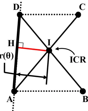
relative to the ICR. The effective moment arm is defined as the distance between the centre of inertia of the body and the centre of rotation of the knee located where the ligaments cross. This distance is calculated as the altitude from vertex C to side AB in the triangle ABC presented in Fig. 2.
The formula for l(θ) is given by using the definition of sine (‘opposite over the hypotenuse’):
sinα=l (θ)
AC (1)
Then, the sine law relates the angles and the lengths such as
AB sin(π−θ) =
BC sinα =
AC
sinβ (2)
By rearranging the two fractions on the left in (2) with (1), we find
l(θ) = BC×AC
AB ×sin(π−θ) (3)
where
AB =pAC2+ BC2−2×AC×BC×cos(π−θ)
(a)
Fig. 2. (A) Body segment lengths expressed as a fraction of body height, adapted from [1] and (B) schematic showing the different angles to work out the effective moment arm.
anthropometric measurements that approximate the human body as an assembly of rigid segments.
B. Design Space
The design space for the condylar hinge joint is large because of the number of design variables especially with respect to the geometry of the four-bar mechanism. Also, it is not intuitive what values of design parameters give the best design. Design maps are commonly used in materials selection and structural design [2], [3], compressor design [4] and robotics design [5], [6], [7], [8]. Therefore, it is helpful to produce maps of the design space so that designers can directly select the optimal solutions depending on their requirements. The optimum design of joints is very important in robotics and prosthetics because space and power is generally limited [9], [10].
Moreover, design procedures for the synthesis and opti-mization of four-bar mechanisms have been investigated in other studies [6], [11], [12], [13]. For instance, the design optimization methodology described in [14] and [15] uses an algorithm taking into account multi-criteria functions that reduces the number of design parameters. In their papers, the authors produce performance charts and workspace atlases which give a range of feasible solutions applicable to parallel mechanisms. Therefore, another approach to designing a condylar knee joint is to select a geometry from design charts that map the complete design space.
This paper presents the numerical analysis that was used for mapping the design space of a bio-inspired robotic condylar hinge joint. The results of the complete map for the design space are characterized by the mechanical advantage, sliding ratio and the range of movement. Design charts are produced in order to facilitate the selection for designers of the optimal configuration adapted to their specific applica-tion. The criteria are applied to evaluate the performances of all the different four-bar mechanisms.
II. METHODOLOGY
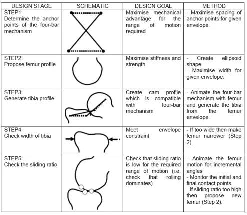
In-house MATLAB script was developed to model the condylar hinge joint and simulate the motion of the four-bar mechanism. The design of an inverted parallelogram mechanism that has a motion that is fully compatible with the motion of a cam mechanism requires specific design goals and an iterative design process. Fig. 3 summarises a 5-step design procedure that can be used to create such a dual mechanism for a given envelope and associated design goals of maximising mechanical advantage and joint stiffness and strength.
The main objective of a typical mechanism design problem is to have the final position and orientation of the end effector at the required location. To do so the designer has to design for a specific number of configurations, which generate a system of equal number of equations and unknowns and that lead to a trading selection of the most suitable solution according to pre-selected criteria.
The following sections describe the different steps of the procedure to develop a condylar hinge joint:
• The initial stage of the design process is to define the four-bar mechanism that gives the best mechanical advantage for a given envelope as it will reduce the required force to carry out movement. This is done by maximising the spacing of the anchor points of the four-bar mechanism for a given envelope.
• The second step involves proposing a femur profile that has potential to give high stiffness and strength. This is done by creating an ellipsoid shape and maximising the width of the femur.
• In step 3, the tibia profile is created by animating the
four-bar mechanism with the femur profile. This was achieved by “attaching” the ellipsoid profile to the top bar and tracking the different the different contact points between each profile.
• In step 4, the width of the tibia must be checked to see if it meets the envelope constraints. If the tibia exceeds the width envelope (because the femur was too wide) then it is necessary to go back to step 2 and reduce the width of the femur.
Fig. 3. Design procedure for the four-bar mechanism and cam mechanism.
III. PERFORMANCEMAPS
A. Criteria
For each case of the 4-bar mechanism geometries, four performance criteria were calculated:
1) Peak mechanical advantage. 2) RMS mechanical advantage. 3) RMS sliding ratio.
4) Angle range.
The mechanical advantage affects actuator selection be-cause the moment applied to the joint via a quadriceps actuator is proportional to the mechanical advantage. In some cases, the peak mechanical advantage may be most important if the maximum load has a repeatable variation during the rotation of the hinge. In other cases the RMS value may be more important if the load is more uniform during the rotation of the hinge.
The sliding ratio can affect actuator selection if the loads on the joint are high, thus creating potentially high friction losses. In general, a low sliding ratio is preferable because this leads to a high degree of rolling which is gives low friction losses and low wear. The sliding ratio is calculated based on analysis of the circumference of the sliding surfaces (see Fig. 4). The range of angular movement of the joint can be another significant performance factor. In some cases, range of movement can also be a design constraint.
The performance criteria is shown in Fig. 4 with the maximum and minimum level of performance seen on the performance maps presented in this paper. The range of performance is large because performance is very sensitive to the exact geometry of the four-bar mechanism.
B. Narrower Femur Profile
Since the human femur has its width bigger than its depth, a femur with a depth bigger than the width was chosen in order to investigate the effect of the profile on
the performances. This case study will demonstrate the sensitivity of the performances to a different structure when the geometry stays constant.
The geometry of a joint is physiologically important and a quantifiable factor contributing to an optimised transmission of forces in joints. With the condylar rapid prototype, this particular profile was chosen in order to assess the impact of a narrower geometry of the bones on the joint performances. Performance maps of the mechanical advantage is shown in Fig. 4. The mechanical advantage (peak and RMS) is maximised by having the lowest aspect ratio of four-bar mechanism (AR=1.0). Also, in the similar way than with the mechanical advantage based on the profile, the highest peak values of mechanical advantage occur at the highest offset angles. The reason for this is that this geometry moves the ICR of the four-bar mechanism by the maximum amount, thus increasing the radius arm by the maximum amount. For low aspect ratio, the highest RMS mechanical advantage occurs at around half of the maximum offset angle and minimum offset gap.
For high aspect ratio, the highest peak and RMS me-chanical advantage occurs both at maximum offset angle and minimum offset gap. The reason for this is that the geometry of the four-bar mechanism is maximised by the starting angle.
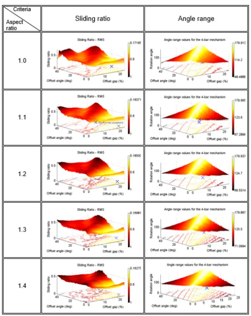
IV. PERFORMANCEMAPS OFSLIDINGRATIO AND
ANGLERANGE ONNARROWERFEMURPROFILE
The results for the sliding ratio and angle range is shown in Fig. 5. For the sliding ratio, as the femur rotates, the distance travelled by the point of contact with the generated tibia can double between increments. The reason for this is that the femur rolls and slides because ICR follows and elliptical pathway that moves backward.
Fig. 4. Mechanical advantage for aspect ratio from 1.0 to 1.5.
[image:4.612.181.430.392.706.2]Fig. 6. Diagram of the four-bar mechanism and its various angles.L1,
L2,L3,L4are known.θ: input angle,θ1is set according to the lengths of
L1andL3.
because it is very sensitive to the exact profile of the tibia. The best sliding ratios (lowest value of SR) occur at low offset angles and high offset gaps. However, at very high values of offset gaps the sliding ratio suddenly becomes very range. Therefore it is advisable to avoid high values of offset gap of say greater than 20%.
For each value of aspect ratio the sliding ratio has a mimimum value of between 0.1 to 0.2. This shows that it is possible to select a condylar rapid prototype where rolling predominates.
The range of movement of joint is highest when the offset angle is large because it goes through a significant angle before the top bar becomes horizontal and there is therefore more potential angular movement.
V. ANALYSIS OF THEKNEEJOINT FOR THEDESIGN OF ANEENERGYSAVINGEXOSKELETON
The design of an energy saving exoskeleton it is necessary to identify the potential areas of energy saving within human anatomical features. This is done by investigating the biome-chanics of human joints and movements while performing daily activities such as walking, running or squatting. In this paper the knee joint is further detailed. During movement, the knee joint not only rotates but also slides due to its moving centre of rotation and its moment arm changing.
To extract the moment arm, which is the distance from the ICR, located where the diagonals (ligaments) cross, and the line of action for the quadriceps muscle, an analysis of the kinematic motion of the four-bar is necessary.
In Fig. 6, a diagram of the four-bar mechanism with its annotated angles is drawn. According to the mechanism configuration, the vector loop method is used and produces, once rearranged with the angles, the following equations that have a sum value equal to zero.
By projecting the vectorial relation in a coordinate system, the input/output law of the system is obtained.
Projection onX−axis:l1cosθ1
+l2cosθ2−l3cosθ3= 0 Projection onY −axis:l1sinθ1
+l2sinθ2+l3sinθ3= 0
(4)
Fig. 7. Schematic of the MA (red).
(X) :l
1cosθ1+l2cosθ2−l3cosθ3= 0 (Y) :l1sinθ1+l2
p
1−cosθ22+l3 p
1−cosθ32= 0
(
(X) : cosθ3=l1cosθ1l+l2cosθ2 3
(Y) :l1sinθ1+l2 p
1−cosθ22+l3 p
1−cosθ32= 0
(X) : cosθ3= l1cosθ1+ll 2cosθ2 3
(X)⇒(Y) :l1sinθ1+l2 p
1−cosθ22
+l3 r
1−l1cosθ1+l2cosθ2 l3
2
= 0
Therefore, in equation (4) of order 2, the only unknown remaining is θ2. The equation can be solved by using
the MuPad Symbolic interface in MATLAB. Once θ2 is
calculated andθ3found, trajectories of C and D are obtained
and the ICR can be plotted.
As defined earlier in this section, the moment arm, or also called mechanical advantage (MA), is the perpendicular distance between the ICR and the direction of action of the force. During movement, the ICR moves backward therefore the MA varies depending on the configuration of the four-bar mechanism. To determine the variation of the MA, it is essential to identify the line of action of the force, here noted AD (Fig. 7).
Since the trajectory of point D and I have been established, the straight line (AD) is described by the equation:
(AD) : y = mADx + pAD (5)
Where mAD and pAD are the coefficients calculated in function of the coordinates of A and D. The distance IH is then calculated using the following formula:
IH = |mAD√xI−yI+ pAD| 1 + mAD2
(6)
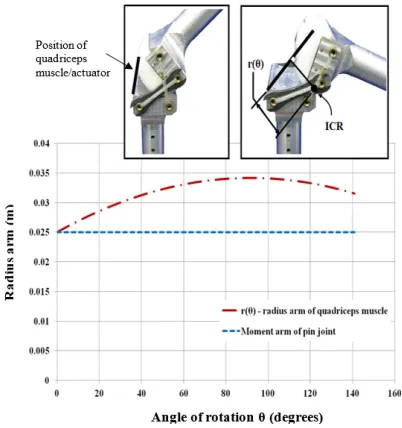
[image:5.612.78.278.50.158.2]Fig. 8. Curve of the moment arms, r(θ) and constant moment arm for a pin joint.
instantaneous centre of rotation of the knee joint. Fig. 8 shows how the radius arm of the quadriceps muscle varies with angle of rotation of the knee.
The graph shows that as the knee bends, the radius arm of the quadriceps muscle increases. This is advantageous because the actuation has a greater moment arm when the loads on the knee are greater. By comparing a pin joint and the bio-inspired joint, the radius arm increases by up to 30% which means that the required actuation force is decreased by up to 30%. Therefore, the bio-inspired hinge joint has a favourable mechanical advantage.
VI. CONCLUSION
This paper has presented a bio-inspired design of hinge joint for robotic limb applications. The joint mimics the four-bar motion of the cruciate ligaments and mimics the condylar surfaces of the femur and tibia bones in the human knee joint. The bio-inspired design has the same desirable features of a human knee joint including a moving centre of rotation, high strength, high stiffness, compactness and locking in the upright position. The paper has also presented a 5-step design procedure to produce a combined inverted parallelogram mechanism with a cam mechanism. The condylar hinge joint also has an out-of-plane stiffness approximately double that of a pin-jointed hinge of a given volume when angular contact bearings are used. These characteristics are important for mobile robotic applications in order to improve the efficiency of locomotion. The bio-inspired design process has advantages since the overall methodology would enable the development of ‘smart joint’ that can incorporate the advantageous features from anatomical joints such as the elbow or the shoulder.
ACKNOWLEDGMENT
The authors acknowledge the support of the UK Engi-neering and Physical Sciences Research Council (EPSRC)
under grant reference EP/P022588/1 and to acknowledge the support of Professor Chris Melhuish from the Bristol Robotics Laboratory, University of the West of England.
REFERENCES
[1] R. Drillis, R. Contini, and M. Bluestein,Body segment parameters. New York University, School of Engineering and Science, 1969. [2] X.-J. Liu, J. Wang, and F. Gao, “Performance atlases of the workspace
for planar 3-dof parallel manipulators,” Robotica, vol. 18, no. 5, pp. 563–568, 2000.
[3] P. Weaver, M. Ashby, S. Burgess, and N. Shibaike, “Selection of materials to reduce environmental impact: a case study on refrigerator insulation,”Materials & Design, vol. 17, no. 1, pp. 11–17, 1996. [4] D. Pasini, D. Smith, and S. Burgess, “Structural efficiency maps
for beams subjected to bending,” Proceedings of the Institution of Mechanical Engineers, Part L: Journal of Materials: Design and Applications, vol. 217, no. 3, pp. 207–220, 2003.
[5] S. Burgess, D. Pasini, and K. Alemzadeh, “Improved visualisation of the design space using nested performance charts,”Design Studies, vol. 25, no. 1, pp. 51–62, 2004.
[6] X.-J. Liu, J. Wang, and F. Gao, “Performance atlases of the workspace for planar 3-dof parallel manipulators,” Robotica, vol. 18, no. 5, pp. 563–568, 2000.
[7] H.-J. Su and J. M. McCarthy, “Synthesis of bistable compliant four-bar mechanisms using polynomial homotopy,”Journal of Mechanical Design, vol. 129, no. 10, pp. 1094–1098, 2007.
[8] A. C. Etoundi, S. C. Burgess, and R. Vaidyanathan, “A bio-inspired condylar hinge for robotic limbs,” Journal of Mechanisms and Robotics, vol. 5, no. 3, p. 031011, 2013.
[9] E. I. Rivin,Mechanical design of robots. McGraw-Hill, Inc., 1987. [10] S. C. Burgess and A. C. Etoundi, “Performance maps for a bio-inspired
robotic condylar hinge joint,”Journal of Mechanical Design, vol. 136, no. 11, p. 115002, 2014.
[11] S. Masouros, A. Bull, and A. Amis, “(i) biomechanics of the knee joint,”Orthopaedics and Trauma, vol. 24, no. 2, pp. 84–91, 2010. [12] M. Nordin and V. H. Frankel, “Biomechanics of the knee,”Basic
biomechanics of the musculoskeletal system, vol. 2, pp. 115–134, 1989. [13] D. W. Hong and R. J. Cipra, “Visualization of the contact force so-lution space for multi-limbed robots,”Journal of Mechanical Design, vol. 128, no. 1, pp. 295–302, 2006.
[14] H.-J. Su and J. M. McCarthy, “Synthesis of bistable compliant four-bar mechanisms using polynomial homotopy,”Journal of Mechanical Design, vol. 129, no. 10, pp. 1094–1098, 2007.
[15] T. Schwenke, L. Borgstede, E. Schneider, T. Andriacchi, and M. Wim-mer, “The influence of slip velocity on wear of total knee arthroplasty,”
![Fig. 2.(A) Body segment lengths expressed as a fraction of body height,adapted from [1] and (B) schematic showing the different angles to workout the effective moment arm.](https://thumb-us.123doks.com/thumbv2/123dok_us/575727.557173/2.612.58.296.58.230/segment-expressed-fraction-adapted-schematic-showing-different-effective.webp)