x-OSC: A Versatile Wireless I/O Device For Creative/Music Applications
Sebastian Madgwick University of Bristol, Bristol, UK
Thomas Mitchell
University of the West of England, Bristol, UK
ABSTRACT
This paper introduces x-OSC: a WiFi-based I/O board in-tended to provide developers of digital musical instruments with a versatile tool for interfacing software to the physical world via OSC messages. x-OSC features 32 I/O channels supporting multiple modes including: 13-bit analogue in-puts, 16-bit PWM outputs and serial communication. The optimised design enables a sustained throughput of up to 370 messages per second and latency of less than 3 ms. Access to settings via a web browser prevents the need for specific drivers or software for greater cross-platform com-patibility. This paper describes key aspects of x-OSC’s de-sign, an evaluation of performance and three example ap-plications.
1. INTRODUCTION
The ubiquity of high-performance computational devices is raising the baseline expectations of computer literacy and the prioritisation of programming skills within school curricular [1]. As technology becomes increasingly famil-iar, an appetite for technological experimentation is giving rise to a new range of development platforms designed to make technological innovation accessible to all [2]. Princi-pal examples include the Processing language/environment [3], which provides powerful abstractions for the devel-opment of cross-platform graphical software, and the Ar-duino development board, which has empowered artists, designers, and makers to create embedded hardware solu-tions [4].
Developers of digital musical instruments (DMIs) are no-table users and creators of modern devices that are opti-mised to connect real-world electronics with music com-position and performance software [5]. For example, Axel Mulder’s I-Cube system [6], Fl´etyet al’s EtherSense [7] and Kartadinata’s gluion [8] each represent solutions that have emerged from research into interactive music sys-tems. Similarly, the interface device presented in this paper has been designed to meet the challenges associated with live music performance and represents a high-performance, robust, potable, low-latency and highly-compatible inter-face device suitable for a wide range of applications. The following sections of this paper will set out the context
Copyright: c2013 Sebastian Madgwick et al. This is an open-access article distributed under the terms of the
Creative Commons Attribution 3.0 Unported License, which permits unre-stricted use, distribution, and reproduction in any medium, provided the original author and source are credited.
RS422 USB OSC
Audio Sensor
Processing Custom
Dongle
Software RGB LED Haptic Motor
Bend Sensors
IMU
RS232 RS232 Custom
[image:1.595.315.542.172.358.2]Hub
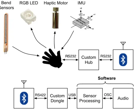
Figure 1. Data flow diagram for one of two data gloves in the current version ofThe Gloves
leading to the development of x-OSC with a review of re-lated work; the implementation, specification and perfor-mance results will then be summarised; before closing with a range of example applications and concluding remarks.
2. BACKGROUND: THE GLOVES
The authors of this paper are developers of a glove-based gestural music interaction system built in collaboration with the singer/songwriter Imogen Heap [9,10]. The current system structure and communication channels are shown in Fig.1.
3. RELATED DEVICES
Developers of DMIs require devices that have the capacity to connect software applications with a range of electronics that can measure control input and produce output actua-tion. There is an abundance of electronic devices appropri-ate for this task, which significantly differ in their intended use and design.
3.1 Development Boards
Many devices represent highly accessible development boards with accompanying software tools that simplify the embedded firmware development process. For example, Arduino [4] provides a range of development boards with a unique programming language (based on Wiring) and de-velopment environment (based on Processing [3]). Simi-larly, the Create USB interface may be programmed in ei-ther BASIC, the Arduino language or C, to cater for users with differing levels of expertise [12].
3.2 Interface Devices
Typically, developers of DMIs produce firmware that en-ables multiple analogue or digital I/O (input/output) chan-nels to be accessed by software running on a host com-puter. However, a range of interface devices are designed to obviate the need for embedded development by enabling the device channels to be configured in firmware, commu-nicating with the host software via a MIDI, USB or net-work link, often without the need for device drivers to be installed. In this sense, the device interface can be con-sidered as a direct extension of the developer’s host soft-ware [13].
MIDI Devices
The I-CubeX Digitizer [6] and the Eroktronix MidiTron [14] enable the reception of sensor readings and the livery of actuator control messages via MIDI. Both de-vices enable configuration for different scenarios via MIDI SysEx commands. However, These devices are limited by their dependence on the MIDI hardware specification and consequently require additional peripherals for the host com-puter.
USB Devices
Modern MIDI-based interface devices, such as the Eobody3 [15], bypass this hardware limitation by using the USB MIDI standard to connect directly to the host computer. Further configurable USB interface devices include the GAINER [16] and Arduino installed with the Firmata li-brary [13]. Both examples implement a serial protocol to enable I/O pins to be configured using commands from a compatible host application, without the need for user firmware development.
Open Sound Control (OSC) Devices
[image:2.595.321.529.49.195.2]As modern computers come equipped with high-speed net-work support, OSC represents an ideal communications protocol for interface devices. OSC is a widely supported (over 80 languages/platform implementations [17]),
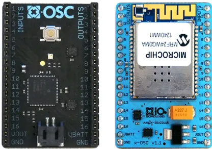
Figure 2. x-OSC board top (left) and bottom (right), size: 31×47 mm
lightweight network protocol designed specifically for com-munication between computers and multimedia devices [18]. Devices such as IRCAM’s EtherSense [7] and glui’s gluion [8], connect to a host computer via an Ethernet connection to exchange I/O and configuration messages. Schmeder and Freed’s uOSC [11] provides a versatile firmware solu-tion for connecting software with a range of development boards via a USB serial connection using the OSC proto-col.
Wireless Devices
The development boards and interface devices discussed above are limited by their dependence on wires (although serial connections may be tunnelled through Bluetooth, XBee or similar radio devices), however, many practical application scenarios demand untethered portable solutions. IRCAMs WiSe Box [19] digitiser provides host access to 16 analogue input readings at up to 333.3Hz via OSC when connected via a WiFi access point. The high message rate, small form factor and WiFi support make the WiSe Box ideal for collaborative interactive music system develop-ment. However, as the device is unable host ad-hoc net-works, configuration is achieved over a custom USB se-rial connection/protocol. Furthermore, it is designed ex-clusively for the acquisition of sensor readings, making the WiSe Box unsuitable for actuation/feedback, a feature which is often considered essential for the development of DMIs.
4. X-OSC
x-OSC is a wireless I/O board that provides host software access to 32 multi-functional I/O channels via OSC mes-sages over WiFi. There is no user programmable firmware or software to install making x-OSC immediately compat-ible with any WiFi-enabled platform.
jumper wires. Other features include a battery connector, battery level measurement, an RGB status LED and a ping button. The on-board WiFi module incorporates a PCB antennae eliminating the need for an external antennae.
4.1 Inputs
16 dedicated inputs (0 V to 3.3 V) can be independently configured to be either analogue or digital. Digital inputs can be configured to use internal pull-up/down resistors and to minimise latency their state is only transmitted on change. All 16 analogue inputs are sampled with 13-bit resolution and sent simultaneously at a specified update rate up to 370 Hz. Analogue mode inputs also provide a
comparefunction to send a message each time a specified threshold is crossed. This enables low-latency threshold detection without the need for a high message rate.
4.2 Outputs
16 dedicated outputs can be independently configured to digital, pulse or PWM modes. In digital mode, an out-put can be set to high or low enabling simple control of LEDs, relays, or generation of control logic signals. In pulse mode, an output can be triggered to generate a pulse with a period of 1 ms to 1 minute at a resolution of 1 ms. This may be useful for momentary actuators such a solenoid driving the strike mechanism of a percussive in-strument. An output in PWM mode can generate a PWM waveform from 5 Hz to 250 kHz with a duty cycle reso-lution up to 16-bit. PWM is commonly used as a DAC where fixed frequency and variable duty cycle approximate an analogue signal. For example, this may be used to con-trol the brightness of a light or the speed of a motor. Each 3.3V output is driven by a line-driver to protect the micro-controller outputs and source/sink up to 50 mA per chan-nel.
4.3 Serial
In addition to modes described above, the first four inputs and outputs can be configured to serial mode with each transmit and receive pair utilising a dedicated hardware UART module. Each serial channel supports baud rates in the range 9600 to 1 M baud and incorporates a 2 kB buffer to ensure high throughput without loss of data. Re-ceived serial data is framed before being sent asOSC-blob
messages. Framing boundaries are determined by a user defined buffer size, timeout and optional framing charac-ter.
4.4 Network modes
[image:3.595.312.538.50.327.2]x-OSC can be configured to operate in one of two network modes: ad hoc or infrastructure. In ad hoc mode, x-OSC creates a network for other devices to join. Multiple de-vices can connect to a single x-OSC with simultaneous ac-cess to its I/O. Infrastructure mode allows x-OSC to con-nect to an existing network. The device IP address can be configured to be static or use DHCP to be assigned an ap-propriate IP address by the network server. The assigned IP address can be discovered by pressing the ping button,
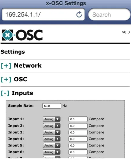
Figure 3. x-OSC settings viewed on web browser
which causes x-OSC to broadcast a message indicating the IP address over the network. Alternatively, a ping message can be sent to x-OSC by another network device. Infras-tructure mode enables multiple x-OSCs to operate on the same network and be addressed by multiple host devices also connected to the network. A connection to a router can also provide an inherent interface to x-OSC via Ether-net or from remote interEther-net connections.
4.5 Configuration via browser
An embedded web server enables all internal settings to be configured using a web browser, see Fig. 3. Settings may be viewed and modified during run-time without interrupt-ing the OSC messages. Incorrect network settinterrupt-ings can ren-der x-OSC inaccessible; access can be re-established by pressing and holding the ping button to restart the device in ad hoc mode with default settings.
4.6 OSC messages
x-OSC transmits and receives OSC messages using the User Datagram Protocol (UDP) transport layer.
Although OSC is widely supported, many platforms fail to incorporate the full specification [11]. To maximise compatibility, x-OSC messages are limited to four of the fundamental data types: int32, float32, OSC-string and
OSC-blob. For example, Boolean arguments are repre-sented by an int32 and null arguments by an argument value of zero. In addition to this, messages sent to x-OSC may useint32andfloat32interchangeably.
messages include battery data, a ping message and override commands for the built in LED.
5. OPTIMISED DESIGN
x-OSC’s design was optimised for throughput, latency and high-performance I/O. A key aspect of this design is the use of Microchip’s TCP/IP stack, a networking library for Microchip microcontrollers and Microchip WiFi modules. Many competitor WiFi devices incorporate an internal net-working stack to provide a self-contained and easy-to-use module compatible with any microcontroller. However, in-corporation of the stack on the host processor provides the firmware with direct access to low-level stack processes and enables specific optimisations to be implemented.
5.1 Hardware
The key hardware components are Microchip’s dsPIC33EP512MC806 digital signal controller and MRF24WG0MA WiFi module. The MRF24WG is Mi-crochip’s highest performing WiFi module, capable of up to 5 Mbit sustained throughput and maximum transmit power of +18 dBm. The dsPIC33E was specifically cho-sen for its high-performance and wide range of advanced peripherals:
• 16-bit architecture, 70 MIPS and 53 kB RAM repre-sents one of Microchip’s highest performing micro-controllers to minimise latency caused by heavy pro-cessing tasks such as maintaining the TCP/IP stack, processing OSC messages and floating-point opera-tions.
• 512 kB of program space is enough to hold the main
application, TCP/IP stack, and embedded webpage server content while leaving space for future devel-opments. The current firmware size is 177 kB.
• Two ADCs (10-bit at 1.1 MHz and 12-bit at 500
kHz) and 9 direct memory access (DMA) channels enable the implementation of the 16 analogue inputs with minimal CPU loading.
• 16 PWM modules with dedicated timers in addition
to nine general purpose timers for precise scheduling of I/O functionality with minimal CPU loading.
• Remappable peripherals are essential to enable the
multifunctional modes of x-OSC’s I/O channels.
5.2 Firmware
The firmware uses Microchip’s TCP/IP Stack v5.42.06 with only essential application modules enabled. The stack’s SPI library was modified to use the maximum 10 MHz full-duplex baud rate supported by the dsPIC33E. A key aspect of the optimised design is the extensive use of the advanced peripherals offered by dsPIC33EP so that most I/O functionality may be executed without CPU interven-tion.
Analogue sampling of the inputs utilises the 1.1 MHz 10-bit ADC, 16-channel multiplexer and DMA to yield measurements of all 16 inputs at 533 Hz with 13-bit res-olution. This was achieved by configuring the ADC to
continuously sample at 546 kHz while the multiplexer se-quenced between each of the 16 inputs each ADC sample. A DMA channel assigned to the ADC writes each sample to a predefined pattern of address in RAM inping-pong
mode to alternate between two alternative blocks of RAM every 1024 samples (64 samples per channel) enabling the ADC to continue sampling uninterrupted without the risk of overwriting unprocessed samples. When analogue in-put data is required, the CPU comin-putes a scaled mean of each channel’s 64 samples to yield a 13-bit result through oversampling [20]. The battery voltage was measured in a similar way using the 12-bit ADC and computing the mean of 16 samples to attenuate noise.
The 16 independent PWM outputs utilise 16 16-bit PWM modules with dedicated timers and four of the nine general purpose timers as clock references. Each output channel is able to achieve both an independent frequency and duty-cycle between 5 Hz and 250 kHz and 8.1-bit to 16-bit res-olution (dependent on the frequency) respectively. Use of 4 general purposes timers provides each PWM timer with simultaneous access to all possible prescaling options to maximise the PWM frequency resolution and range. The frequency range of 5 Hz to 250 kHz is divided by approx. 218,000 steps with a non-linear resolution of 3.66µs at lower frequencies and 14.31 ns at higher frequencies. The output pulse mode is achieved by a 1 kHz CPU interrupt for 1 ms resolution and inherent synchronisation between pulses performed on different channels.
5.3 Power consumption
The optimisations of throughput, latency and I/O perfor-mance come at a cost in power consumption. The current consumption was measured as up to 225 mA in infrastruc-ture mode or up to 300 mA in ad hoc mode. A 1000 mAh lithium polymer battery (of a similar physical size to x-OSC) may be expected to last approximately 3 hours.
6. EVALUATION OF PERFORMANCE
An important aspect of WiFi performance is the network connection delay. This may be critical if a connection is lost unexpectedly. The time taken to connect to a router was found to be approximately 30 seconds. The time taken for x-OSC to create an ad hoc network was found to be ap-proximately 15 seconds, however recreating this network after another device had connected required only 6 sec-onds. Infrastructure configurations were found to provide better throughput and latency performance than ad hoc. The following investigations represent a host computer con-nected to a router via an Ethernet cable, the router hosts the WiFi network to which x-OSC is connected. The only net-work traffic was between x-OSC and the host machine.
6.1 Throughput
Function Generator
XOR Frequency Counter
A B
C
output = input A
B
C
1 Hz input
Delayed 1 Hz output
[image:5.595.310.543.45.223.2]Pulse width = delay
Figure 4. Experimental setup for evaluation of closed-loop latency
0 5 10 15 20 25
0 0.2 0.4 0.6 0.8
Closed−loop latency (ms)
Normalised number of samples
[image:5.595.55.288.50.162.2]Ideal Under load
Figure 5. Closed-loop latency evaluation (distribution of approximately 50,000 samples)
alone and when three x-OSCs are sending to the same host machine simultaneously. As only three prototype modules were available at the time of writing, performance with more than three x-OSC devices could not be investigated.
6.2 Closed-loop latency
Closed-loop latency was quantified as the delay between a physical change on an input and the resulting physical change on an output. This measurement incorporates sam-pling jitter, sending to the host application via WiFi, pro-cessing by the host application and sending of the respond-ing output change to x-OSC via WiFi. A 1 Hz square wave was used to create a changing input signal and a PC appli-cation was written to set an output equal to that input. Both the input and output signals were connected to the inputs of an XOR gate to generate a 2 Hz wave form with a pulse width equal to the closed-loop latency. This pulse width was logged using a frequency counter for several hours. This arrangement is shown in Fig. 4. Investigations were conducted for idealconditions where only the waveform input and output messages were sent and received, and for
loadedconditions where x-OSC was simultaneously send-ing analogue input messages to the host application at 200 packet/s. The results are shown in Fig. 5. Under loaded conditions the mean closed-loop latency was measured at 10.9 ms, for ideal conditions, this figure dropped to 5.5 ms. It is therefore assumed that under ideal conditions the latency for sending input data only is approximately 2.75 ms.
[image:5.595.61.271.216.331.2]A previous x-OSC design used the older MRF24WB WiFi module in place of the MRF24WG. Investigations found
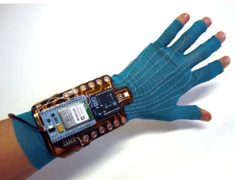
Figure 6. The x-OSC data glove, incorporating an IMU, RGB LED, vibration motors and e-textile flex sensors
the MRF24WB provided a maximum throughput of 290 packet/s which would reduce to 100 packet/s with three devices sending simultaneously. The closed-loop latency was found to be 8.4 ms in ideal conditions and 15.8 ms when also sending analogue input packets at 200 Hz.
7. EXAMPLE APPLICATIONS
In this section three example applications of x-OSC will be described to provide practical and divergent examples of its potential utility.
7.1 Data Gloves
The primary motivation for the development of x-OSC was to enhance the glove-based musical system discussed in section2. Compatibility with the x-OSC glove (made by Hannah Perner-Wilson and shown in Fig.6) was achieved using the oscpack C++ library [21]. Nine analogue inputs were used to take readings from the resistive e-textiles sen-sors, and one serial input was used to receive accelerom-eter, gyroscope, magnetometer and orientation data from an IMU. Five PWM outputs were used to control an RGB LED and a pair of haptic feedback motors.
Each x-OSC glove operates in infrastructure mode, con-necting to a router positioned close to the performer to re-duce the risk of WiFi interference [19]. The remaining six input, and 11 output channels provides scope for future de-velopment.
7.2 Solar Wind Chime
Figure 7. Solar wind chime: top of aluminium tube with electromagnet (left) and solar wind chime assembly design (right)
tubes of the solar wind chime, (shown in Fig.7). Further-more, DC signals can be used to stimulate the physical dis-placement of the tubes. The solar wind readings are inter-preted and remapped to OSC messages within a Processing sketch, using the oscP5 library [22].
7.3 Hexapod Robot
To demonstrate application of x-OSC beyond typical cre-ative technology domains, x-OSC is used to connect soft-ware running on the host computer with a Sparkfun 12 servo hexapod robot, equipped with two IR range sensors as shown in Fig. 8. The software, written in C# using the Ventuz OSC library [23], implements a basic gait and avoidance algorithm which is used to drive twelve PWM output channels connected to each servo and two analogue input channels to take readings from the IR sensors.
8. CONCLUSION
x-OSC was developed for creative/music applications but its high-performance and versatility make it a valuable tool for any application requiring a real-time interface between software and electronic sensors or actuators. The hardware and firmware design has been optimised to achieve sus-tained throughput of up to 370 messages per second and latency of less than 3 ms. The widely supported OSC pro-tocol enables any WiFi enabled platform to interface to the 32 multi-functional I/O channels without the need for spe-cific drivers or software. Real-time access to settings via browser provides a convenient interface during develop-ment and eliminates the need for supporting software.
Acknowledgments
The authors would like to thank the Pervasive Media
Stu-Figure 8. Sparkfun 12 servo hexapod robot with IR range sensors
dio, South West Microelectronics iNets, the European Re-gional Development Fund, the University of the West of England and the following individuals: Verity McIntosh, Clare Reddington, Imogen Heap, Helen White, Balazs Janko, Peter Bennett, Hannah Perner-Wilson, Kelly Snook and Adam Stark.
9. REFERENCES
[1] R. Noss, R. Cox, D. Laurillard, R. Luckin, L. Plow-man, E. Scanlon, and M. Sharples, “System up-grade: Realising the vision for UK education.” London Knowledge Lab, London., Project Report, 2012.
[2] C. Anderson,Makers: The New Industrial Revolution. Crown Business, 2012.
[3] C. Reas, B. Fry, and J. Maeda., Processing: A Pro-gramming Handbook for Visual Designers and Artists.
The MIT Press., 2007.
[4] D. Mellis, M. Banzi, D. Cuartielles, and T. Igoe, “Ar-duino: An open electronic prototyping platform,” in
Proceedings of the Conference on Human Factors in Computing (alt.chi), 2007.
[5] E. R. Miranda and M. M. Wanderley,New Digital Mu-sical Instruments: Control And Interaction Beyond the Keyboard. A-R Editions, 2006.
[6] A. Mulder, “The i-cube system: Moving towards sen-sor technology for artists.” inProceedings of the 6th International Symposium on Electronic Art., 1995.
[7] E. Fl´ety, N. Leroy, J.-C. Ravarini, and F. Bevilac-qua, “Versatile sensor acquisition system utilizing net-work technology,” inProceedings of the International Conference on New Interfaces for Musical Expression, 2004.
[image:6.595.309.543.48.227.2][9] T. Mitchell and I. Heap, “Soundgrasp: A gestural inter-face for the performance of live music,” inProceedings of the International Conference on New Interfaces for Musical Expression, 2011.
[10] T. J. Mitchell, S. Madgwick, and I. Heap, “Musical in-teraction with hand posture and orientation: A toolbox of gestural control mechanisms.” inProceedings of the International Conference on New Interfaces for Musi-cal Expression, 2012.
[11] A. Schmeder and A. Freed, “uOSC: The open sound control reference platform for embedded devices,” in
Proceedings of the International Conference on New Interfaces for Musical Expression, 2008.
[12] D. Overholt, “A system for sketching in hardware: Do-it-yourself interfaces for sound and music computing,” in Proceedings of the Sound and Music Computing Conference, 2012.
[13] H.-C. Steiner, “Firmata: Towards making microcon-trollers act like extensions of the computer,” in Pro-ceedings of the International Conference on New In-terfaces for Musical Expression, 2009.
[14] Eroktronix Labs, “Miditron.” [Online]. Available: www.miditron.com
[15] E. Gallin and M. Sirguy, “Eobody3: a ready-to-use pre-mapped and multi-protocol sensor interface,” in Pro-ceedings of the International Conference on New In-terfaces for Musical Expression, 2011.
[16] S. Kobayashi, T. Endo, K. Harada, and S. Oishi, “Gainer: a reconfigurable i/o module and software li-braries for education,” inProceedings of the Interna-tional Conference on New Interfaces for Musical Ex-pression, ser. NIME2006, 2006.
[17] The Center For New Music and Audio Technology (CNMAT), UC Berkeley, “Open sound control,” 2013. [Online]. Available:www.opensoundcontrol.org
[18] M. Wright, “Open sound control: an enabling tech-nology for musical networking,” Organised Sound, vol. 10, no. 3, 2005.
[19] E. Fl´ety, “The wise box : a multi-performer wireless sensor interface using wifi and osc,” in Proceedings of the International Conference on New Interfaces for Musical Expression, 2005.
[20] “Avr121: Enhancing adc resolution by oversampling,” Atmel Corporation, Tech. Rep., 2005.
[21] R. Bencina, “A simple C++ open sound control (OSC) packet manipulation library,” 2013. [Online]. Available:https://code.google.com/p/oscpack/
[22] A. Schlegel, “The oscp5 library,” 2013. [Online]. Available:www.sojamo.de/libraries/oscP5