Performance Improvement of Simplified
Synchronous Generators Using
an Active Power Filter
Al-Hussein Abu-Jalala
∗, Tom Cox
∗, Chris Gerada
∗, Mohamed Rashed
∗, Tahar Hamiti
†and Neil Brown
‡ ∗Power Electronics and Motor
Control Group
The University of Nottingham
Nottingham, UK
[email protected]
†
Department of Vehicle
Electrification
VEDECOM Institute
Versailles 78000, France
[email protected]
‡
Cummins Power Generation
Peterborough, PE1 5EL
United Kingdom
[email protected]
Abstract—Active power filters (APF) are used to improve power quality and are commonly connected in parallel with the load at the point of common coupling (PCC). They are used to compensate for harmonics from nonlinear loads, for reactive power compensation and/or balancing mains currents. This paper will investigate the effect of using an APF to improve the output power quality of a simplified synchronous generator (SSG) with distorted back-EMF. The work will further investigate the use of an APF in parallel to improve the transient response of synchronous generator without damper bars, in order to control the dynamic response from a sudden change in the connected load. Using an APF, simulation results show significant improvements in both generator output current quality and transient response to load step changes without damper bars.
Index Terms—Synchronous generator, Damper bars, Skewless generator, Active power filter, Four legs converter, Finite element analysis.
I. INTRODUCTION
Active power filters (APF) have been used to improve power quality since the 1980s [1]. They are connected in parallel with the load at the point of common coupling (PCC). The main functions of the APF are compensating harmonics from nonlinear loads, balancing source currents and reactive power compensation. Shunt active power filters topologies and control algorithms have been widely discussed in the literature [2]–[5].
The impact of harmonics on a synchronous generator will be apparent both mechanically and electrically. The mechanical effect will appear as vibration on the generator shaft with electromagnetic torque pulsation, and will shorten the lifetime of the generator. The electrical effect will result in distorted current and voltage waveforms in both stator and rotor wind-ings and this will cause excess heating and generator losses, lowering efficiency of power conversion [6], [7].
Synchronous generator designs commonly use 2/3 pitch winding to decrease the harmonics of the induced back-EMF, but this also has the effect of decreasing the fundamental induced back-EMF voltage by pitch factor (kp). Synchronous generator stators are also commonly skewed to compensate for the slot harmonics, which complicates the manufacturing
process. Finally, rotor damper cages are used to improve the dynamic performance of synchronous generators, however the damper cage reduces the effective pole area and field, introduces significant extra cost and complexity to the rotor manufacturing process and will cause rotor heating if harmon-ics are present in the generator.
This paper will examine firstly the effect of connecting an APF in parallel to a simplified synchronous generator (SSG) with distorted back-EMF due to an unskewed stator with a full pitch winding. The APF will be used to improve the power quality supplied to the load if the load is linear or compensate load harmonics if the load in nonlinear. The second part of this work will investigate the improvement of transient stability of the proposed generator without damper bars and APF during a rapid change in connected load.
II. SYSTEMCONFIGURATION
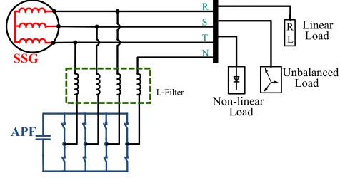
The proposed system is a three-phase four wire system consisting of a simplified synchronous generator (SSG), four leg active power filter (APF), interface L-filter and a load, which may be linear or nonlinear, and balanced or unbalanced as shown in Fig.1.
Unbalanced Load Non-linear
Load R L
Linear Load
SSG
APF
L-Filter
[image:1.612.317.555.548.673.2]R S T N
Fig. 1:The proposed system
A. The Proposed Generator
modifica-tions made to the stator in order to simplify the manufacturing process and increase the generator capacity. That commercial generator has a2/3pitch winding with a skewed stator, while the proposed form uses a skewless stator with a fully pitched winding and is shown in Fig.2. In the proposed generator the neutral wire is removed to prevent triplen current harmonics from reaching the load. A load side neutral will be supplied from the converter (APF).
[image:2.612.337.550.136.194.2](a) (b)
Fig. 2: Full pitch skewless generator (a)2D finite element analysis (FEA) model (b) Experimental prototype (the proposed generator)
According to [8], the fundamental back-EMF of the SG can be written as:
Erms= 4.44f kdkpNΦpole (1)
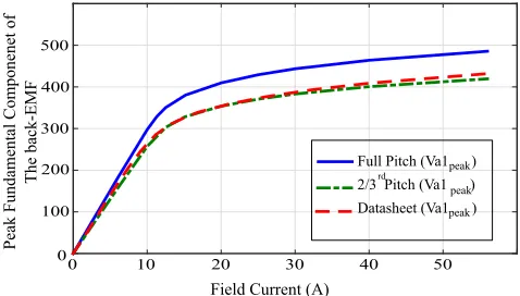
wherefis the induced voltage frequency,kdis the distribution factor, kp is the pitch factor, N is the number of turns and Φpole is the flux per pole. Due to the increased pitch factor the back-EMF voltage of the proposed generator will be higher about15%than the standard generator at the same flux density. Fig.3 shows the open circuit test curve for both the standard and the proposed modified generator from 2DFEA modelling, along with datasheet values for the standard generator. As can be seen from Fig.3for the same fundamental output voltage the field current can be reduced from 15 A in the standard generator to 11.2 A in the proposed generator, if the power quality can be maintained.
500
400
300
200
100
00 10 20 30 40 50
Full Pitch (Va1 )
Peak Fundamental Componenet of
The back-EMF 2/3 Pitch (Va1 )peak peak
Datasheet (Va1 )peak
rd
[image:2.612.320.558.333.461.2]Field Current (A)
Fig. 3:Open circuit test for the proposed generator and the standard commercial generator
B. Synchronous Generator Model
A Matlab Simulink model was developed as shown in Fig.4. based on the inductance matrix of the proposed generator at different rotor positions taken from the 2DFEA model.
The flux linkage and the induced back-EMF is calculated by
Lookup
table dtd
Generator circuit
Ln×n
Ψn×1 En×1 Current measurements
To the load Rotor
position
Fig. 4:Block diagram of the generator simulink matlab model
(2) and (3) respectively.
Ψ[n×1]=L[n×n]×I[n×1] (2)
Eback−EM F[n×1] =
dΨ[n×1]
dt (3)
In this model, the effects of saturation were neglected and the field current was assumed to be constant. Fig.5. shows
Vamatlab
Generator Back-EMF (
V)
Time (sec) 450
300 150 0 -150 -300 -450
0 0.005 0.01 0.015
Vbmatlab Vcmatlab Vc
FEA Va
FEA Va
FEA
Fig. 5:Comparison between FEA and Matlab models of the proposed generator
the comparison between the back-EMF from 2DFEA and the Simulink model. It can be seen that these are in very close agreement
C. Speed controller and diesel engine dynamic model
When considering transient behaviour and damping, a model of the mechanical system driving the generator is re-quired. The speed loop controller consists of a regulator, diesel engine transfer function (to represent throttle actuator and engine delay) and the mechanical equation of a synchronous generator (we assume the damping coefficient is equal to zero) and the developed electromagnetic equations are given in (4) and (5) respectively.
Tm−Te=Jdwr
dt (4)
Te= 3 2
P
[image:2.612.55.294.570.706.2]K
-* r
w +
1+T3s s(1+T4s)(1+T5s)
-+ 1+T1s
1+T2s
1 Js Tm
r w Throttle
actuator
Regulator Engine
Delay Td Generator Inertia Te
[image:3.612.317.559.56.174.2]1 1+Tds
Fig. 6: Block diagram of speed controller that used in transient response simulations
III. HARMONIC COMPENSATION
The harmonic compensation process can be divided into three stages. The first stage is calculating the voltage phase angle at the point of common coupling (PCC) by Dual Second Order Generalised Integrator (DSOGI-PLL) [10]. The second stage is extracting the reference currents which are the currents that should be injected at the PCC to compensate current harmonics, and this done in the simulation by the synchronous reference frame (SRF) d-q technique [11] as illustrated in (6) to (9).
id iq
=M
ia ib ic
(6)
Where M the transformation matrix
M = 2 3
cos(θ) cos(θ−2π
3 cos(θ+
2π
3)
−sin(θ) −sin(θ−2π
3 ) −sin(θ+
2π
3)
(7)
Thenid andiq are passed through a high pass filter to get the ac contentid˜ andiq˜ in the currentsid andiq respectively.
id f ilter
−−−−→i˜d (8)
iq f ilter
−−−−→i˜q (9)
where i˜d and i˜q are the reference currents i∗d and i
∗
q respec-tively.
The last stage is calculating the APF reference voltages that needed to inject the reference currents into the PCC, and the technique was used in the simulation is a synchronous refer-ence frame PI controller (SRF-PI) with decoupling between direct-axis and quadrature-axis components (d and q) as given in in (10) and (11).
vd∗= `vd−ωLiq+vgd (10)
vq∗= `vq+ωLid+vgq (11)
where vd∗ is the direct axis component of the reference voltage, where vq∗ is the quadrature axis component of the reference voltage, ω is fundamental frequency (rad/sec),L is the filter inductance (H), vgd is the direct axis component of the grid voltage and vgq is the quadrature axis component of the grid voltage. Fig.7 shows the block diagram of SFRI-PI controller
+
-PI*
d
i
d
i
-vgd
vgq *
d
v
*
q
v
dv
′
+
wL wL +
+
+
+
PI*
q
i
-q
v
′
+q
i
*
a
v
*
b
v
*
c
v
θ
2
3
Fig. 7:Block diagram of SRF-PI current controller
Simulation Results
This simulation was carried out for the system in Fig.1 with interface filter (5mH) and three different load types: Linear, balanced nonlinear and unbalanced nonlinear load. All three tests used a constant field current and generator speed. The simulation was done for 2 sec, and the APF enabled at t = 0.5 sec. The current waveforms of the generator, load, and APF were analysed.
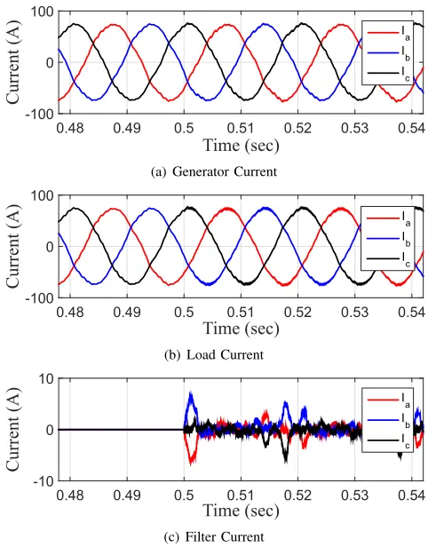
1) Balanced Linear Load: In this simulation a linear load was connected to the generator (36kW) at rated voltage400V line to line. The output generator current, load current and filter current are show in Fig. 8.With the APF in operation, the total harmonic distortion (THD) of the load currents is reduced from3.3% to around2.5%.
Time (sec)
0.48 0.49 0.5 0.51 0.52 0.53 0.54
Curr
ent (A)
-100 0 100
Ia Ib I
c
(a) Generator Current
0.48 0.49 0.5 0.51 0.52 0.53 0.54
-100 0 100
Ia Ib Ic
Time (sec)
Curr
ent (A)
(b) Load Current
0.48 0.49 0.5 0.51 0.52 0.53 0.54
-10 0 10
Ia I
b
I
c
Time (sec)
Curr
ent (A)
[image:3.612.65.274.63.125.2](c) Filter Current
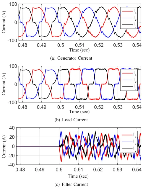
[image:3.612.317.558.406.714.2]2) Balanced Non-Linear Load: To simulate a nonlinear balanced load a three phase diode bridge and RL load was connected to the generator. When the APF was switched on the THD in the generator current decreased from12.5%before switching APF on to 5.2% after switching APF on. Fig 9 shows the generator, the load and the filter before and after the compensation.
Time (sec)
0.48 0.49 0.5 0.51 0.52 0.53 0.54
Curr
ent (A)
-100 0 100
I
a
I
b
Ic
(a) Generator Current
0.48 0.49 0.5 0.51 0.52 0.53 0.54
-100 0 100
Ia I
b
I
c
Curr
ent (A)
Time (sec)
(b) Load Current
Time (sec)
0.48 0.49 0.5 0.51 0.52 0.53 0.54
Curr
ent (A)
-40 -20 0 20 40
Ia Ib Ic
[image:4.612.317.558.52.359.2](c) Filter Current
Fig. 9:Generator, load, and filter currents with nonlinear balanced load
3) Unbalanced Non-Linear Load: In this simulation a single phase diode bridge is added to the previous simulation and connected between phase A and the fourth leg of the converter (neutral point). As can be seen from Fig. 10 the APF decreased THD in the generator current to12.5%to5.5%and supplied the single phase load when it was connected.
IV. IMPROVINGTRANSIENTRESPONSE OFSGWITHOUT
DAMPERBARS
The damper bars in a SG improve dynamic stability during load perturbation by damping the oscillation in SG response. When there is a sudden change in SG load, the SG speed will drift from the synchronous speed. This change in synchronous speed induces currents in the damper bar circuit and these currents produce torque which acts to drive the rotor towards synchronous speed. When the SG does not have damper bars, sudden changes in load will cause more fluctuation in SG speed and load angle and can potentially lead to SG desynchronization with the grid and pullout. To decrease the effect of sudden load changes on a SG without damper bars,
Time (sec)
0.48 0.49 0.5 0.51 0.52 0.53 0.54
Curr
ent (A)
-100 0 100
Ia Ib Ic
(a) Generator Current
0.48 0.49 0.5 0.51 0.52 0.53 0.54
-100 0 100
I
a
I
b
Ic
Time (sec)
Curr
ent (A)
(b) Load Current
0.48 0.49 0.5 0.51 0.52 0.53 0.54
-40 -20 0 20
40 I
a
I
b
I
c
Time (sec)
Curr
ent (A)
[image:4.612.54.296.149.471.2](c) Filter Current
Fig. 10:Generator, load, and filter currents with nonlinear unbalanced load
an active power filter (APF) may be used with the SG to compensate for the load step by introducing a compensatory filter step current that decays exponentially to allow a return to normal operating conditions, as shown in Fig 11.
Filter current
time current
SG current Load current
Fig. 11: Proposed filter, load, and generator currents during a step load change for the generator without damper bars and APF
[image:4.612.320.560.473.626.2]current and electromagnetic torque to decrease gradually until it equals the load current.
Simulation Results
An exciter model (IEEE type-1) ) was used to maintain the output voltage constant during load changes. The simulation period was6sec, the generator is started with a RL load (R= 5 Ω,L= 2.5mH). At timet= 1.5secthe load was doubled and at timet= 3secthe load was returned back to the initial value.
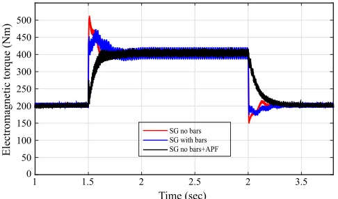
Fig. 12, shows a comparison between the proposed SSG with and without damper bars for speed fluctuation during a sudden change in load as described. As Fig. 12, shows, the disturbance in the generator speed was increased when damper bars were not present (as expected), but when the APF was connected the speed disturbance became much smaller even than that of the SSG with damper bars. In addition the transient electromagnetic torque was reduced when the APF was connected as can be seen from Fig. 13 giving less speed fluctuation with the APF when load steps were applied.
rated speed
Time (sec) 3.5
1 1.5 2 2.5 2
1440 1460 1560
1480 1500 1520 1540
Generator Speed (rpm
)
[image:5.612.55.293.317.448.2]SG no bars SG with bars SG no bars+APF
Fig. 12: Speed response to sudden change in the generator loading with and without APF
Time (sec)
3.5
1 1.5 2 2.5 2
50 100 400
150 200 250 300
Electromagnetic torque (Nm)
450 500
0
SG no bars SG with bars SG no bars+APF
Fig. 13: Developed electromagnetic torque at sudden change in the generator loading with and without APF
V. CONCLUSIONS
The effect of adding an active power filter in parallel with a simplified synchronous generator has been investigated. The APF can be integrated with a simplified synchronous generator
to improve its performance and supply good quality power from a simple generator with a poor quality output waveform at the point of common coupling (PCC). This allows the use of simplified generators with reduced complexity and manufacturing cost without compromising the quality of power delivered to the load.
In addition, it has been shown that the APF can be used to improve the transient stability of a synchronous generator without damper bars, giving improved stability compared to systems using damper bars while also allowing for a signif-icant simplification of the rotor design and construction and improving the rotor magnetic circuit.
The work in this paper is currently undergoing experimental validation using a commercial synchronous generator, modi-fied to include a full pitch wound skewless stator.
REFERENCES
[1] D. Chen and S. Xie, “Review of the control strategies applied to active power filters,” inIEEE International Conference on Electric Util-ity Deregulation, Restructuring and Power Technologies. Proceedings, vol. 2, April 2004, pp. 666–670 Vol.2.
[2] M. El-Habrouk, M. K. Darwish, and P. Mehta, “Active power filters: a review,”IEE Proceedings - Electric Power Applications, vol. 147, no. 5, pp. 403–413, Sep 2000.
[3] H. L. Jou, K. D. Wu, J. C. Wu, C. H. Li, and M. S. Huang, “Novel power converter topology for threephase four-wire hybrid power filter,” IET Power Electronics, vol. 1, no. 1, pp. 164–173, March 2008. [4] M. I. M. Montero, E. R. Cadaval, and F. B. Gonzalez, “Comparison of
control strategies for shunt active power filters in three-phase four-wire systems,”IEEE Transactions on Power Electronics, vol. 22, no. 1, pp. 229–236, Jan 2007.
[5] P. Dey and S. Mekhilef, “Current controllers of active power filter for power quality improvement: A technical analysis,”Automatika–Journal for Control, Measurement, Electronics, Computing and Communica-tions, vol. 56, no. 1, 2015.
[6] J. q. Wang, P. c. Song, C. h. Cui, J. k. Li, and T. Yang, “Analysis of operation of synchronous generator under the distortion of harmonic current,” in Asia-Pacific Power and Energy Engineering Conference, March 2012, pp. 1–4.
[7] W. Fan and Y. Liao, “Impacts of flickers, harmonics and faults on synchronous generator operations,” in Proceedings of the 2012 44th Southeastern Symposium on System Theory (SSST), March 2012, pp. 220–225.
[8] C.-M. Ong, Dynamic simulation of electric machinery: using MAT-LAB/SIMULINK. Prentice Hall PTR Upper Saddle River, NJ, 1998, vol. 5.
[9] R. Shi, X. Zhang, L. Fang, H. Xu, C. Hu, Y. Yu, and H. Ni, “Research on power compensation strategy for diesel generator system based on virtual synchronous generator,” in IEEE 8th International Power Electronics and Motion Control Conference (IPEMC-ECCE Asia), May 2016, pp. 939–943.
[10] P. Rodriguez, R. Teodorescu, I. Candela, A. V. Timbus, M. Liserre, and F. Blaabjerg, “New positive-sequence voltage detector for grid synchronization of power converters under faulty grid conditions,” in Power Electronics Specialists Conference, 2006, pp. 1–7.
[image:5.612.54.297.502.645.2]