1 The influence of shot peening on the fatigue response of Ti-6Al-4V surfaces subject to different machining processes
Zhengkai Xua, J. Dunleaveyb, M. Antarb, R. Hoodc, S.L. Sooc, G. Kucukturkc,d, C.J. Hydea*, A.T. Clarea
a Advanced Component Engineering Laboratory (ACEL), University of Nottingham, University Park, NG9 2SH, UK
b Manufacturing Technology Centre, Pilot Way, Ansty Business Park, Coventry, CV7 9JU, UK
c Machining Research Group, Department of Mechanical Engineering, School of Engineering, University of Birmingham, Edgbaston, Birmingham, B15 2TT, UK
d Department of Mechanical Engineering, Faculty of Engineering, Gazi University, Maltepe, Ankara, Turkey
*Corresponding author: Christopher.Hyde@nottingham.ac.uk
Abstract
Machining processes are known to drastically impact the performance and lifetime of a component subjected to
fatigue in service. Therefore, understanding the effect of manufacturing processes on surface integrity is vital to
determine their suitability for any given application. As part of a wider study investigating multiple production
operations, results are presented here which characterise the fatigue performance and failure mechanisms of
Ti-6Al-4V specimens subject to conventional (end milling, surface grinding) and non-conventional machining
processes (abrasive waterjet machining, wire electrical discharge machining, large area electron beam melting).
Post process shot peening was then applied on each of the 5 different surfaces generated and the resulting fatigue
response similarly evaluated. The abrasive waterjet machined specimens generally exhibited the longest fatigue
life, particularly at higher applied stress (³ 700 MPa) irrespective of surface condition. Despite the difference in
process mechanisms, fatigue results for the milled and wire electrical discharge machined surfaces were
comparable. Examination of the fatigue specimen fracture surfaces however, revealed that the locations of crack
initiation were inconsistent for the different processes and conditions assessed. In general, post process shot
peening increased the fatigue strength / life of all the evaluated specimens, regardless of the base machining
operation.
2 1. Introduction
Machining strategy can significantly influence the resulting workpiece surface condition/integrity, which has a
direct bearing on component fatigue properties and therefore the viability of the material/component in service.
Achieving appropriate surface integrity (SI) is imperative particularly for high-value or safety critical parts such
as those in the aerospace industry, which have extremely stringent tolerance and quality requirements. Field et al.
[1] were the first to introduce an approach for assessing workpiece surface integrity by correlating the effect of
surface changes/alterations produced after machining against a range of mechanical properties and metallurgical
characteristics (e.g. surface finish, micro hardness, microstructure, residual stress, fatigue performance), which
were classified into 3 levels of ‘data sets’. While this provided a useful guideline for the academic research
community, aerospace companies tend to employ internal/proprietary surface integrity criteria tailored specifically
to their individual acceptance standards [2]. Considerable research has been carried out on assessing the influence
of machining operations on workpiece SI of aerospace materials, some of which have been summarised in a recent
review publication [3] as well as in several CIRP keynotes focussed on conventional cutting [4] and abrasive
machining/grinding [5] processes. However, there are comparatively limited numbers of contributions that
consider more complex SI parameters such as fatigue performance (as the trials are generally costly and
time-consuming to perform), which is a critical concern to the aerospace industry. According to Bhaumik et al. [6],
approximately 60% of the total in-service failures in aerospace components are caused by fatigue.
Non-conventional machining methods involving energy beams (such as laser and electron beams) or plasma
sources where the mechanism of material removal is not based on mechanical shearing have attracted increasing
interest from the aerospace industry in recent years as alternatives to traditional techniques for machining high
strength aerospace materials. However, their deployment is still somewhat limited due largely to the thermal
nature of such processes which are known to induce adverse workpiece integrity effects such as recast layer
formation and heat affected zones, thereby impacting on performance in service [7]. Therefore, in the context of
aerospace part manufacture, it is necessary to better study and compare the effects of different machining
processes on component fatigue performance as such data is not currently evident in the literature.
Milling and grinding are two of the most established conventional machining operations utilised in the fabrication
of aero-engine components as they are mechanical deformation based processes that typically induce compressive
residual stress regimes in the workpiece material and hence more likely to produce favourable fatigue
3 was investigated. Reducing workpiece surface roughness (Ra) from 1.64 µm to 0.67 µm was shown to improve
the specimen’s fatigue life by 43.22%. In a similar study by Moussaoui et al. [9] involving milling of Ti-6Al-4V
specimens, surface roughness (Ra) however was not found to have a significant influence on fatigue life, as the
residual stress generated was the dominant factor in determining fatigue performance (as the residual stress varied
from a neutral condition to -264 MPa, the number of cycles to failure increased by 2.5 times). Rangaswamy et al.
[10] studied the grinding of Ti-5Al-2.5Sn alloy in both dry and wet conditions. The dry ground (without lubricants)
workpieces exhibited lower fatigue strength than the un-machined materials, with fatigue life decreasing with the
increase of cutting speed. In contrast, wet grinding (with lubricants) increased the materials’ fatigue performance
when compared with non-ground materials. In conventional machining processes, a ‘white layer’ is occasionally
observed when inappropriate machining conditions are applied, which can appear white and featureless under an
optical microscope after etching of the workpiece specimen cross section with an appropriate chemical reagent.
Guo et al. [11] reported that the presence of a white layer following hard turning and surface grinding of AISI
52100 steel led to a 7.6 fold reduction in fatigue life due to detrimental tensile residual stresses of up to ~2000
MPa generated within the white layer.
In addition to standard cutting operations, an abrasive waterjet (AWJ) can be applied as a surface treatment
technique [12] where the process erodes and deforms the near surface of the workpiece, subsequently introducing
compressive residual stresses in the subsurface as a result of the associated peening effect. Thus, similar to the
condition found in the study by Moussaoui et al. [9], an enhancement of fatigue resistance can be expected. In
work by Arola et al. [13], AWJ peened AISI 304 stainless steel and Ti-6Al-4V titanium alloy workpieces
demonstrated considerable improvement in fatigue resistance compared to non-surface treated specimens, with
10% and 25% increase in endurance strength respectively.
In large area electron beam melting (LAEBM), the kinetic energy of an incident electron beam is applied to
achieve fine polishing of metal surfaces [14]. Previously, several similar processes were studied to enhance
workpiece surface integrity. Proskurovsky et al. [15] applied pulsed electron-beam to modify the surfaces of
several popular materials, which include titanium alloys (BT8M and BT18Y) as well as aluminium alloys (Al2024
and Al6061). In all cases, resultant workpiece microhardness, wear and corrosion resistance together with fatigue
strength were significantly improved. Particularly, the fatigue resistance of the EB-treated titanium alloy was
almost doubled when compared against corresponding untreated specimens. Okada et al. [16] applied LAEB
4 reduced from 20 µm to 3 µm. Furthermore, both hardness and corrosion resistance were improved after the
finishing treatment. According to Farayibi et al. [17], the surface enhancement function of pulsed electron beam
irradiation is also applicable for the surface preparation of laser additive manufactured structures.
Wire electrical discharge machining (WEDM) applies discrete electrical discharges which are generated between
a current carrying wire (tool electrode) and workpiece across a dielectric medium. This causes the material in
close proximity of the wire to melt and vaporise. A principal advantage of WEDM is that its performance is not
constrained by the workpiece material’s hardness, mechanical strength or toughness [18]. The effects of EDM on
workpiece surface integrity have been widely studied. A review by Kumar et al. [19] highlighted that almost all
of the process parameters applied in EDM can have a marked difference in the thickness of the damaged surface
layers. Gökler and Ozanözgü [20] studied the effects of cutting parameters on surface roughness in the WEDM
process of three different ferrous alloys (1040, 2379 and 2738 steel), where a method to determine the proper
parameter combinations for the desired roughness was demonstrated. Mower [21] reported a 15% to 30% decrease
in the fatigue life of WEDM machined Ti-6Al-4V specimens compared to conventionally milled surfaces, which
was attributed to the presence of a recast layer in the former. Developments in EDM generator technology over
the past decade involving control of ultrahigh frequency (> 1 MHz) and short duration pulses have enabled
significant improvement in WEDM process capability, particularly with respect to minimising/eliminating
adverse recast layer formation and related surface/subsurface damage.
Aspinwall et al. [22] evaluated the performance of modern ‘minimum damage’ WEDM systems when machining
10 mm thick Inconel 718 nickel based superalloy and Ti-6Al-4V titanium alloy by utilising a multiple cut strategy
comprising a series of roughing and finishing/trim passes. Initial recast layer thickness of 6–11 µm following the
roughing operation was found to decrease essentially to zero on both materials after 4 successive trim passes.
Furthermore, variation in workpiece microhardness was marginal with no discernible heat affected zones,
suggesting that any residual thermal damage was minimal. Similar trials were undertaken by Antar et al. [23] on
alternative nickel (Udimet 720) and titanium (Ti-6Al-2Sn-4Zr-6Mo/Ti6246) alloy workpieces. Average recast
layer thickness was < 2 µm after the 4th trim cut, although minor reductions in subsurface microhardness (~10% below bulk value) extending to a depth of ~30 µm was recorded in both materials. Subsequent modification of the
discharge pulse profile and associated electrical parameters produced equivalent low levels of damage but which
was achieved with only 2 trim cuts (after the roughing pass), together with near neutral surface residual stress and
5 720 [25] and Ti6246 [26] workpieces machined using the updated WEDM parameters were found to be within
~10% of corresponding high speed milled specimens. Alias et al. [27] analysed the effects of machine feed rate
when WEDM of Ti-6Al-4V using brass wire. The results showed that the kerf width decreased with increasing
feed rate while conversely, both material removal rate and resulting Ra (surface roughness) understandably
exhibited rising trends. In research reported by Klocke et al. [28], the differences in fatigue strength and other
surface conditions caused by grinding and WEDM were considered. The results showed that although ground
specimens had lower surface roughness, the WEDM workpieces possessed better fatigue strength.
In order to improve workpiece surface integrity following machining operations, shot peening has been evaluated
by a number of researchers as a post-processing method to increase fatigue resistance by introducing compressive
residual stresses in the surface layer [29]. Work by Jiang et al. [30] and Takahashi and Sato [31] demonstrated
that shot peened Ti-6Al-4V surfaces possessed superior fatigue resistance compared to specimens without
post-processing treatment. In the former study, shot peening was performed at both room and elevated temperatures
(150°C) with resulting fatigue limits of the treated specimens found to increase by 9% and 10% respectively,
compared to the untreated specimens. Applying a second series of shot peening (re-shot peening) after completing
50% of the estimated fatigue loading cycles was revealed to be a potential method to further augment fatigue life
[30]. Similarly, the investigation by Takahashi and Sato [31] indicated that the specimens’ fatigue limits increased
by 25% following shot peening as opposed to the non-treated test pieces.
The present paper aims to compare the fatigue performance of Ti-6Al-4V surfaces produced using various
conventional and non-conventional machining processes. The influence of post process shot peening was also
investigated together with an analysis of workpiece fractography.
2. Experimental test methodology
2.1. Overview
The experimental strategy employed is shown in Fig. 1. Five subtractive (end milling, surface grinding, AWJ,
WEDM, LAEBM) based surface preparation methods were evaluated and applied to produce the test specimens
used in this study. Half of the specimens were subsequently subjected to post-process shot peening, which was
carried out by Sandwell UK. The Almen strip test procedure, as defined by SAE standard J442 [32], was used to
ascertain the peening intensity while the coverage was determined by the exposure time. The intensity describes
6 The shot peening operation involved two stages, each utilising a defined media and peening intensity as shown in
Table 1. Both sets of specimens (with and without post-processing) were then fatigue tested and the results
analysed.
Fig. 1 Experimental strategy
Table 1 Shot-peening strategy
Stage 1
Media: ASH110 (0.011”) cast steel shot
Intensity: 0.0075” Almen A.
Coverage: 100%
Stage 2
Media: 75-150 µm glass bead
Intensity: 0.005” Almen N
Coverage: 100%
2.2. Specimen preparation
The fatigue test specimens for the machining processes were made from Ti-6Al-4V supplied by All Metal Services
Ltd. and prepared in line with the route described in Fig. 2. Rectangular blanks were initially cut from a larger
block of material and the faces ground down to the dimensions as shown in Fig. 2(a). The test surface of the
specimens was then produced by reducing the height of the blanks from 13 to 10 mm as shown in Fig. 2(b), using
7 selected parameter levels are representative of finishing conditions for the respective processes. The sharp
longitudinal edges/corners bordering the primary evaluation surface were then machined using a special 1 mm
radius milling tool to negate any edge concentration effects during fatigue testing, see Fig. 2(c). The parameters
utilised for the radiusing operation was a cutting speed of 80 m/min, feed rate of 0.1 mm/rev and depth of cut of
0.1 mm.
8 Table 2 Operating parameters employed for the machining processes evaluated
Machining process Machining process parameters
Milling
Cutting speed = 80 m/min
Feed-rate = 0.1 mm/rev
Depth of cut= 0.1 mm
Tool: 10 mm diameter end mill (4 fluted)
Cutting environment = Water based emulsion (15 bar)
Surface grinding
Grinding speed = 30 m/s
Feed-rate = 400 mm/min
Depth of cut = 6 µm per pass
Wheel rotational speed = 3750 rpm
Wheel abrasive = SiC
Cutting environment = Flood coolant
AWJ
Pressure = 1000 bar
Stand-off =100 mm
Relative grit feed = 4/9
Speed = 4000 mm/min
Abrasive particles = Garnet
LAEBM
Cathode voltage = 40 kV
No. of shots = 20
WEDM
Voltage = 80 V
Ignition current = 5 A
Pulse off-time = 8 µs
Pulse on-time = 0.7 µs
Dielectric = Deionised water
9 The areal surface roughness (Sa) of all specimens was measured with an Alicona Infinite Focus microscope prior
to test commencement. The three-point flexure fatigue test was carried out using an RUMUL Testronic machine.
All tests were undertaken at room temperature (20 ± 2°C). Specimens were tested using a three-point bending
arrangement, as shown in Fig. 3, with a loading frequency of between 80-82 Hz. Several preliminary trials were
carried out to determine the appropriate mass (inertia) for the oscillating components of the test machine in order
to ensure that the correct load frequency (~80 Hz) is consistently applied during the fatigue experiments.
Fig. 3 Three-point flexure fatigue testing arrangement schematic
Stresses induced were calculated using the bending relationship outlined in Equation 1 [33]:
𝝈𝒎𝒂𝒙=
𝟑 ∙ 𝑷𝒎𝒂𝒙∙ 𝑳 𝟐 ∙ 𝒃 ∙ 𝒕𝟐
Equation 1
where σmax is the maximum stress level, Pmax is the maximum applied load, L is the distance between supports, b
is the specimen width and t is specimen thickness. As the results presented are a ranking/comparison of the as–
received samples to the shot peened samples, no correction factor has been applied to this equation. All samples
were tested under the sample conditions (geometry, load, etc.).
The stress ratio (R), which is defined as the minimum stress applied divided by the maximum applied stress was
set to 0.1 based on a study conducted to examine the effect of load ratio on stress intensity in Ti-6Al-4V [34] and
to enable comparison of the current work with other similar investigations. Fatigue testing parameters employed
are shown in Table 3. For each stress level, 3 tests were carried out.
Table 3 Fatigue testing parameters (R=0.1)
10
1 900 495 90 405
2 800 440 80 360
3 700 385 70 315
4 600 330 60 270
5 475 261.25 47.5 213.75
A Nikon ECLIPSE LV100ND microscope was applied to check the as-processed and post-processed surfaces. A
Hitachi SEM TM3030 and Nikon Stereo Microscope was used to image the shot peened and fractured specimen
surfaces. All of the micrographs presented in the following sections were from tests undertaken at 800 MPa.
3. Results
The specimens, upon testing, deformed towards one fixed direction as shown in Fig. 4. There exists a neutral axis
along which the stress is zero. The compressive and tensile stress zones are located next to the neutral axis as
shown in Fig. 4. The stress distribution in tested specimens is explained in Fig. 5. The stress changed from tensile
gradually to compressive, with the largest stress magnitude at the midpoint of treated surface. This is therefore
expected to be the origin of fracture [33]. Apart from the treated surface, all the other faces were ground and
should possess similar fatigue resistance.
11 Fig. 5 Stress distribution in the cross section of tested specimen
The basic surface response of the treated specimens before (as-processed) and after (post-processed) shot peening
is shown in Fig. 6. In general, post-processing significantly affected the surface appearance in all cases. The
distinct surface features/topography produced by the different machining techniques were partially or totally
eliminated by shot peening. Table 4 lists the typical surface roughness results due to each process and following
shot peening.
12 Table 4 Surface roughness (Sa) of the as-processed and post-processed specimens
Sa (µm) Milling Grinding AWJ LAEBM WEDM
AP 1.23 1.38 10.93 1.88 0.47
PP 1.74 1.72 6.13 1.87 1.53
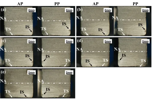
Fig. 7 shows the fracture surfaces of treated specimens after fatigue testing. Crack progression marks can be
clearly seen in all of the specimens. The distance between the fracture initiation sites and the treated surface are
listed in Table 5.
Fig. 7 Fracture surfaces of fatigue tested (a) milled, (b) ground, (c) AWJ, (d) LAEBM and (e) WEDM specimens, where IS indicates fracture initiation site, TS indicates treated surface
The results shown in Fig. 7 indicate that the fracture initiation site is not consistently on the treated surface but
sometimes closer to the neutral axis on the side face of the specimens. This is an indication of the enhancement
in mechanical properties (fatigue strength of the material) due to the surface treatment, particularly in the case of
the milled and AWJ workpieces. Therefore, despite being at a position of lower applied stress, failure initiated on
13 this behaviour was evident in all of the post process shot peened specimens, irrespective of the initial machining
operation.
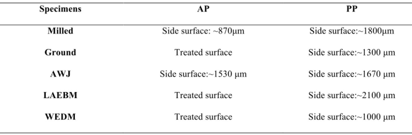
Table 5 Location of fracture initiation sites in the evaluated specimens (as shown in Fig. 7 ) and the distance between the treated surface and the initiation sites position on the side surface
Specimens AP PP
Milled Side surface: ~870µm Side surface:~1800µm
Ground Treated surface Side surface:~1300 µm
AWJ Side surface:~1530 µm Side surface:~1670 µm
LAEBM Treated surface Side surface:~2100 µm
WEDM Treated surface Side surface:~1000 µm
3.1. S-N curves
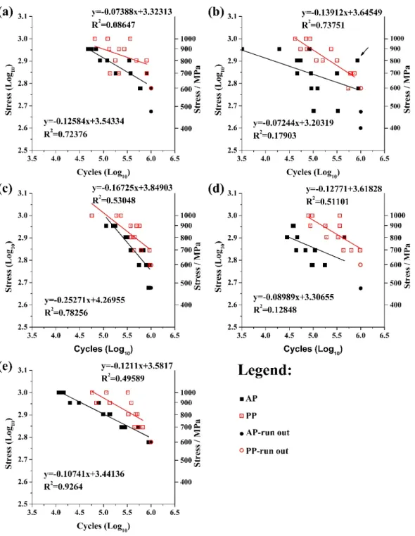
Fig. 8 shows the S-N curves of all tested specimens. Apart from the main (primary) logarithmic axis, a secondary
Y-axis has been included to show the absolute stress value equivalent to the values shown on the primary axis.
Results from regression analysis (BS 2864, 1976 and ASTM E-739-91, 2004) were also incorporated to offer
insight into the quality of the perceived linear relationship. These graphs can be used to predict performance at
other stress levels within the linear region and are thus useful to design engineers. Fatigue run-out was set at
1,000,000 cycles to shorten the overall experimental time. The run-out data showed in Fig. 8 were excluded from
the regression computations, as the trend lines were only intended to describe the S-N region between low-cycle
fatigue and eventual run-out. A description of the run-out tests in each category are given in Table 6. Included in
Fig. 8 are the respective equation of linear regression and the associated coefficient of determination (R2), which indicates the relative strength of the linear relationship between the variables. As a negative correlation is expected
for such relationships, only the absolute values are displayed on the graphs. Correlations (R2) greater than 0.8 in value are generally considered strong, whereas values less than 0.5 are deemed to be weak. Equations and
coefficients of determination for the as-processed groups are listed on the bottom left of the graphs, while the
post-processed equivalents can be found on the top right corners. As shown in Fig. 8, an obvious improvement in
fatigue performance can generally be observed due to post-processing. The LAEBM specimens, however,
14 between the data of the as-processed and post-processed conditions, whereas the benefit of post-processing on
milled and AWJ specimens in particular was less pronounced.
Fig. 8 Log-scale S-N curves following fatigue testing of (a) milled, (b) ground, (c) AWJ, (d) LAEBM and (e) WEDM specimens
There are some data points within, for example, the as-processed data at 800MPa shown in Fig. 8(b), which are
15 assessing suspect results, these data points are within a reasonable range. A particularly suspect example,
highlighted in Fig. 8(b), has been evaluated as follows:
The three measurements (in Log10 form) of cycles to failure at 800MPa are 4.659, 4.733 and 5.933. The value of
5.933, highlighted in Fig. 8(b), is much larger than the other two and is therefore a suspect measurement (𝑥./.).
The mean (𝑥) and standard deviation (𝜎1) of these measurements are 5.109 and 0.715, respectively. Based on the
calculation process provided by Chauvenet’s Criterion [35], the measure of difference (𝑡./.) between the suspect
value 5.933 and the mean value of 5.109 is:
𝑡./.=
𝑥./.− 𝑥
𝜎1 =
5.933 − 5.109
0.715 = 1.15
Equation 2
Referring to the Normal Error Integral table [35], in this case, the probability (𝑃𝑟𝑜𝑏 𝑜𝑢𝑡𝑠𝑖𝑑𝑒 𝑡./.𝜎 ) that a
measurement will differ from 𝑥 by 𝑡./.𝜎1 or more is:
𝑃𝑟𝑜𝑏 𝑜𝑢𝑡𝑠𝑖𝑑𝑒 1.15𝜎 = 1 − 𝑝𝑟𝑜𝑏 𝑤𝑖𝑡ℎ𝑖𝑛 1.15𝜎 = 1 − 0.7499 = 0.25
Equation 3
Therefore, for the 3 measurements at this stress level, the expected number (n) of measurements which will be as
deviance as 5.933 is:
𝑛 = 3×𝑃𝑟𝑜𝑏 𝑜𝑢𝑡𝑠𝑖𝑑𝑒1.15𝜎 = 3×0.25 = 0.75
Equation 4
Since 0.75 is bigger than 0.5 set by Chauvenet’s Criterion [35], which indicates three-fourth of a measurement
will be as deviance as the suspect value 5.933, it is reasonable.
Table 6 Descriptions of the run-out tests in each category
AP PP
Milled 3 tests at 475 MPa, 1 tests at 600 MPa 3 tests at 600 MPa Ground 3 tests at 400 MPa, 1 tests at 475 MPa 3 tests at 600 MPa
16
LAEBM 3 tests at 475 MPa 3 tests at 600 MPa
WEDM 2 tests at 600 MPa 3 tests at 600 MPa
The comparison of fatigue strength due to the different machining processes prior to and following shot-peening
is detailed in Fig. 9. A considerable spread in fatigue performance was evident between the different production
methods in the as-processed condition, with the number of cycles to failure ranging between ~18,000 and
~280,000 at a maximum applied stress of 800 MPa, see Fig. 9(a). The variability in fatigue life amongst the
different processing techniques, however, was significantly reduced following shot peening as shown in Fig. 9(b),
coupled with an enhancement of fatigue strength in all cases. The AWJ machined specimens possessed the best
fatigue resistance particularly at high applied stress levels (³ 700 MPa). A further observation was that the
as-processed milled and WEDM specimens generally displayed similar fatigue response characteristics, with
superior run-out levels compared to the other processes. While with the decreasing of applied stress, the failure
cycles of all specimens become similar.
Fig. 9 S-N curve sections for all (a) as-processed and (b) post-processed specimens
3.2. Fractography
Fig. 10 shows SEM images of the fracture surfaces in the milled specimens. Initiation sites originated at the side
face in both the as-processed and post-processed specimens. Failure in the as-processed specimen occurred near
the interface of the radiused corner and side face of the specimen, see Fig. 10(a), while the corresponding location
17 as depicted in Fig. 10(b). Faint progression marks were visible, which suggests variation in the rate of fatigue
crack growth. Fig. 11 shows high magnification SEM micrographs of fracture initiation sites in the milled
specimens. Large secondary cracks (longer than 50 µm) were seen in the as-processed specimen, while those
present in the post-processed specimen were considerably smaller / shorter (less than 20 µm). This suggests that
shot peening served to reduce the development of cracks. Fatigue striations were also evident in the high
magnification images, which indicate the fracture propagation within these specimens.
Fig. 10 Fracture surfaces in the milled (a) as-processed and (b) post-processed specimens
Fig. 11 High magnification SEM images of fracture initiation sites in the milled (a) as-processed and (b) post-processed specimens
Fig. 12 shows the fracture initiation sites in the AWJ specimens. In both as-processed and post-processed
conditions, the cracks initiated at the side faces of the fatigue specimens at a distance of about 1.6 mm from the
AWJ treated surfaces. Progression marks were similarly observed in these specimens. More detailed SEM images
of the fracture initiation sites are shown in Fig. 13, which indicate comparable fracture conditions between the
18 surfaces denoting the directions of damage propagation. No other signs of flaws were detected in either of the
AWJ specimens other than the appearance of several small cracks. This was possibly due to the effects of
compressive residual stresses most likely imposed by the AWJ operation are more effective compare to that of
shot peening.
Fig. 12 Fracture surfaces of AWJ (a) as-processed and (b) post-processed specimens
Fig. 13 High magnification SEM images of fracture initiation sites in the AWJ (a) as-processed and (b) post-processed specimens
Fig. 14 details the fracture surfaces of the ground, LAEBM and WEDM processed specimens. All 3 as-processed
specimens showed failure initiating on the machined surfaces, see Fig. 14(a), (c) and (e), while the corresponding
shot-peened specimens in Fig. 14(b), (d) and (f) showed fracture commencing from the side faces. In the
high-resolution SEM images, small secondary cracks can be seen in the as-processed specimens as shown in Fig. 15(a)
and (c), while fewer cracks appeared in Fig. 15(e). Conversely in the post-processed specimens, several large
cracks appeared in the WEDM processed specimen as shown in Fig. 15(f). All fracture initiation sites are again
19 (Fig. 11(b)). The fatigue striations highlighted in Fig. 15 indicate the direction of fracture propagation in these
specimens.
20 Fig. 15 High magnification SEM images of fracture initiation sites in the as-processed and post-processed (a) (b) ground, (c) (d) LAEBM and (e) (f) WEDM specimens
Closer inspection of the as-processed LAEBM surfaces revealed another possible subsurface fatigue initiation site
as shown in Fig. 16, which was potentially caused by the surface defect. This was deduced from the appearance
21 Fig. 16 (a) Subsurface fracture initiation site on the as-processed LAEBM specimen caused by surface defect and (b) the higher magnification SEM photo of the defect
4. Discussion
4.1. The influence of machining process and shot-peening on fatigue performance
Based on the surface roughness results detailed in Table 4, shot peening led to an increase in roughness of the
milled, ground and WEDM specimens while the LAEBM specimen remained approximately the same.
Conversely, a reduction in roughness was obtained in the AWJ surfaces, most likely due to ‘smoothening’ of the
high peaks inherent with such processes. The effects of surface roughness on the fatigue performance are not clear
in this case since the residual stress generated during the manufacturing processes is another critical factor.
Moussaoui et al. [37] obtained similar results, i.e. no obvious evidence showing that surface roughness can
significantly affect the fatigue life of a specimens, while higher compressive residual stresses were found to
increase the fatigue life of a specimen.
The S-N curves in Fig. 9 show a trend of improved fatigue performance in all post-processed specimens with
higher run-out stress levels observed in most cases (also can be told from Table 6). Post-processing significantly
lowered the differences of fatigue performance in specimens machined with the various techniques. This may be
due to the fact that shot peening homogenised the features [38] of the machined/built surfaces (as shown in Fig.
6) and also applies enhanced local stress conditions [39]. The only exception was with WEDM, as shown in Fig.
22 The as-processed milled and WEDM specimens were found to have approximately equivalent fatigue
performance in the range of 650-750 MPa, which is in agreement with results reported by Antar et al. [25] and
Soo et al. [26] but contradicts the data published by Mower [21]. This may be the result of differences in the
WEDM parameters and fatigue testing conditions utilised. Mower [21] carried out testing at a frequency of 10
Hz, while the current work entailed a substantially higher loading rate ranging between 80-82 Hz with the
specimens machined using minimum damage EDM generator technology. The post-processed milled specimens
as shown in Fig. 8(a) however displayed erratic fatigue performance with a large spread of values where for
example, the number of cycles to failure at 700 MPa varied between 110,000 and 1,000,000. Results for the
as-processed specimens were more uniform and they usually failed after a longer number of loading cycles. The
S-N curves for both conditions were similar, but the large scatter of data points indicates a greater magnitude of
error.
The surface ground specimens showed inferior fatigue performance relative to the other machining processes
evaluated, possibly due to the relatively mild parameters employed (6 µm depth of cut per pass) and hence likely
lack of any major compressive residual stresses. The results for the as-processed specimens again varied greatly,
with a wide distribution of cycles to failure recorded at almost every stress level, see Fig. 8(b). Conversely,
post-processed surface ground specimens were consistent.
Amongst the as-processed specimen groups, those machined by AWJ generally possess the best fatigue
performance. This can be attributed to the compressive residual stresses generated on the treated surface, which
serve to impede crack formation and growth during fatigue testing [40]. In terms of the post-processed specimens,
the AWJ machined specimen still possessed the best fatigue performance in the high-stress range. The benefits of
shot peening were only discernible at higher applied stress levels, for applied maximum stresses up to 800 MPa,
results for the as-processed and post-processed AWJ specimens, as detailed in Fig. 8(c) were similar. As outlined
by Arola et al. [13], the AWJ treated Ti-6Al-4V specimens showed a rise of 25% in endurance strength, which is
broadly consistent with results reported here.
A marked improvement in fatigue performance was prevalent in the post-processed LAEBM specimens, with the
cycles to failure close to an order of magnitude higher than corresponding as-processed test pieces at most applied
stress levels; see Fig. 8(d). Though the fatigue performance of the as-processed LAEBM specimens was poor
compared to the WEDM ones, the fatigue performance was almost the same after post-processing. Fatigue life
23
4.2. Fractography
Of the 5 as-processed specimens, 2 had fracture initiation sites on the side surface. All specimens had their fracture
initiation sites moved further away from the treated surface after post-processing (as shown in Table 5), this can
be explained as a result of the strengthening mechanism of shot peening. The treated surface and adjacent bulk
material were strengthened by the compressive residual stress generated during shot peening, so that they can
withstand the highest tensile stress, whilst fracture initiated from somewhere with lower fatigue strength in the
specimen. The non-treated side faces have lower fatigue strength compared to the strengthened face, meaning that
these sites act as fracture initiation sites after undergoing more cycles than the as-processed specimens, since the
stress magnitudes applied on the side surfaces are lower. Similar fracture initiation sites movement, i.e. from
strengthened area to less strengthened area, were found in the studies by Hitoshi et al. [41] and Hiroshi et al. [42].
The stress at the side faces is smaller than that in the treated surface, thus specimens normally exhibit a longer
fatigue life.
As shown in Fig. 11, the as-processed milled specimen has much larger cracks on the fracture initiation site than
the post-processed specimen, which mainly due to the applied stress becoming smaller with the increase in
distance between the fracture initiation site and the treated surface (as shown in Fig. 5). This also explains the
reason for the fracture initiation sites of as-processed and post-processed AWJ specimens having similar features.
In the as-processed ground, LAEBM and WEDM specimens, the fracture initiation sites were all located within
the residual stress affected zone. Grinding [43] can normally lead to compressive residual stress below specimen’s
surface with the assistance of vibration, which is able to neutralise part of the external tensile stress, while LAEBM
[44] and WEDM [24] normally results in tensile residual stresses which will boost the detrimental effects of
external tensile stress. Thus, a greater number of large sized cracks can be observed in the as-processed LAEBM
and WEDM specimens (as shown in Fig. 15(c) and (e)). Since the fracture initiation sites in post-processed
specimens were some distance away from the treated surface and with the effects (i.e. residual stress generated
during the process) of shot peening on Ti-6Al-4V normally limited to a depth of around 200 µm [30], the features
of the fracture initiation sites in these locations are mainly dependent on the properties of the bulk material.
5. Conclusions
In this study, the influence of different machining operations on the fatigue performance of Ti-6Al-4V was initially
24 milled, AWJ and WEDM machined surfaces showed better fatigue strength than the corresponding surface ground
and LAEBM specimens although the discrepancy in performance was substantially reduced post shot-peening.
Within the as-processed specimen group, the AWJ surfaces demonstrated the best fatigue performance, especially
in the high applied stress zone where the number of cycles to failure was around ~500,000 at 700 MPa. This was
likely caused by a compound peening effect from both the AWJ and conventional shot-peening operations. The
milled and WEDM specimens were observed to have a similar fatigue life, which was comparable to AWJ at the
lower-stress range below 700 MPa.
In general, the fatigue strength of shot-peened specimens was superior to those in the as-processed state, which is
attributed the induced compressive residual stresses on the test face under maximum tension during testing
regardless of the base surface processing method. However, results from SEM imaging of the fracture surfaces
revealed that a large majority of specimens showed cracks initiating close to the treated surface of the specimens,
either on the processed or side face. In any case, all shot peened fatigue specimens had cracks originating from
the side faces, instead of treated surfaces.
Acknowledgements
The authors would like to acknowledge the support of EPSRC EP/L017121/1 “EPSRC High Value Manufacturing
Catapult Fellowship Centre” which provided support for A. Clare’s engagement with the Catapults. Funding
provided by the Scientific and Technological Research Council of Turkey (TUBITAK) for G. Kucukturk through
the International Researchers Fellowship programme is also gratefully acknowledged. Thanks are also due to
A.M. Abdelhafeez and J. Ashman for their assistance with the milling and grinding fatigue specimen preparation.
References
[1] M. Field, J.F. Kahles, J.T. Canmett. A review of measuring methods for surface integrity. Annals of the CIRP
1972; 21: 219-238.
[2] I.S. Jawahir, E. Brinksmeier, R. M'Saoubi, D.K. Aspinwall, J.C. Outeiro, D. Meyer, et al. Surface integrity in
material removal processes: Recent advances. CIRP Annals - Manufacturing Technology 2011; 60 (2): 603-626.
[3] A. Thakur, S. Gangopadhyay. State-of-the-art in surface integrity in machining of nickel-based super alloys.
25 [4] R. M'Saoubi, D. Axinte, S.L. Soo, C. Nobel, H. Attia, G. Kappmeyer, et al. High performance cutting of
advanced aerospace alloys and composite materials. CIRP Annals - Manufacturing Technology 2015; 64 (2):
557-580.
[5] F. Klocke, S.L. Soo, B. Karpuschewski, J.A. Webster, D. Novovic, A. Elfizy, et al. Abrasive machining of
advanced aerospace alloys and composites. CIRP Annals - Manufacturing Technology 2015; 64 (2): 581-604.
[6] S.K. Bhaumik, M. Sujata, M.A. Venkataswamy. Fatigue failure of aircraft components. Engineering Failure
Analysis 2008; 15 (6): 675-694.
[7] F. Klocke, A. Klink, D. Veselovac, D.K. Aspinwall, S.L. Soo, M. Schmidt, et al. Turbomachinery component
manufacture by application of electrochemical, electro-physical and photonic processes. CIRP Annals -
Manufacturing Technology 2014; 63 (2): 703-726.
[8] C. Yao, D. Wu, Q. Jin, X. Huang, J. Ren, D. Zhang. Influence of high-speed milling parameter on 3D surface
topography and fatigue behavior of TB6 titanium alloy. Transactions of Nonferrous Metals Society of China 2013;
23 (3): 650-660.
[9] K. Moussaoui, M. Mousseigne, J. Senatore, R. Chieragatti, P. Lamesle. Influence of Milling on the Fatigue
Lifetime of a Ti6Al4V Titanium Alloy. Metals 2015; 5 (3): 1148-1162.
[10] P. Rangaswamy, H. Terutung, S. Jeelani. Effect of grinding conditions on the fatigue life of titanium
5Al-2.5Sn alloy. Journal of Materials Science 1991; 26 (10): 2701-2706.
[11] Y.B. Guo, A.W. Warren, F. Hashimoto. The basic relationships between residual stress, white layer, and
fatigue life of hard turned and ground surfaces in rolling contact. CIRP Journal of Manufacturing Science and
Technology 2010; 2 (2): 129-134.
[12] D.D. Arola, M.L. McCain. Abrasive waterjet peening: a new method of surface preparation for metal
orthopedic implants. Journal of biomedical materials research 2000; 53 (5): 536-546.
[13] D. Arola, A.E. Alade, W. Weber. Improving faitgue strength of metals using abrasive waterjet peening.
Machining Science and Technology 2006; 10 (2): 197-218.
[14] J.W. Murray, P.K. Kinnell, A.H. Cannon, B. Bailey, A.T. Clare. Surface finishing of intricate metal mould
structures by large-area electron beam irradiation. Precision Engineering 2013; 37 (2): 443-450.
[15] D.I. Proskurovsky, V.P. Rotshtein, G.E. Ozur, A.B. Markov, D.S. Nazarov, V.A. Shulov, et al. Pulsed
electron-beam technology for surface modification of metallic materials. Journal of Vacuum Science &
26 [16] A. Okada, Y. Uno, N. Yabushita, K. Uemura, P. Raharjo. High efficient surface finishing of bio-titanium
alloy by large-area electron beam irradiation. Journal of Materials Processing Technology 2004; 149 (1–3):
506-511.
[17] P.K. Farayibi, T.E. Abioye, J.W. Murray, P.K. Kinnell, A.T. Clare. Surface improvement of laser clad Ti–
6Al–4V using plain waterjet and pulsed electron beam irradiation. Journal of Materials Processing Technology
2015; 218: 1-11.
[18] K.H. Ho, S.T. Newman, S. Rahimifard, R.D. Allen. State of the art in wire electrical discharge machining
(WEDM). International Journal of Machine Tools and Manufacture 2004; 44 (12–13): 1247-1259.
[19] S. Kumar, R. Singh, T.P. Singh, B.L. Sethi. Surface modification by electrical discharge machining: A
review. Journal of Materials Processing Technology 2009; 209 (8): 3675-3687.
[20] M.İ. Gökler, A.M. Ozanözgü. Experimental investigation of effects of cutting parameters on surface
roughness in the WEDM process. International Journal of Machine Tools and Manufacture 2000; 40 (13):
1831-1848.
[21] T.M. Mower. Degradation of titanium 6Al–4V fatigue strength due to electrical discharge machining.
International Journal of Fatigue 2014; 64: 84-96.
[22] D.K. Aspinwall, S.L. Soo, A.E. Berrisford, G. Walder. Workpiece surface roughness and integrity after
WEDM of Ti–6Al–4V and Inconel 718 using minimum damage generator technology. CIRP Annals -
Manufacturing Technology 2008; 57 (1): 187-190.
[23] M.T. Antar, S.L. Soo, D.K. Aspinwall, M. Cuttell, R. Perez, A.J. Winn. WEDM of aerospace alloys using
‘Clean Cut’ generator technology. in: the 16th International Symposium on Electro-Machining (ISEM XVI),
Shanghai, China; 2010, p. 285 – 290.
[24] M.T. Antar, S.L. Soo, D.K. Aspinwall, D. Jones, R. Perez. Productivity and Workpiece Surface Integrity
When WEDM Aerospace Alloys Using Coated Wires. Procedia Engineering 2011; 19: 3-8.
[25] M.T. Antar, S.L. Soo, D.K. Aspinwall, C. Sage, M. Cuttell, R. Perez, et al. Fatigue response of Udimet 720
following minimum damage wire electrical discharge machining. Materials & Design 2012; 42: 295-300.
[26] S.L. Soo, M.T. Antar, D.K. Aspinwall, C. Sage, M. Cuttell, R. Perez, et al. The Effect of Wire Electrical
Discharge Machining on the Fatigue Life of Ti-6Al-2Sn-4Zr-6Mo Aerospace Alloy. Procedia CIRP 2013; 6:
215-219.
[27] A. Alias, B. Abdullah, N.M. Abbas. Influence of Machine Feed Rate in WEDM of Titanium Ti-6Al-4V with
27 [28] F. Klocke, D. Welling, J. Dieckmann. Comparison of Grinding and Wire EDM Concerning Fatigue Strength
and Surface Integrity of Machined Ti6Al4V Components. Procedia Engineering 2011; 19: 184-189.
[29] P.D. Rufe. Fundamentals of Manufacturing. 3rd ed. Dearborn, Michigan: Society of Manufacturing
Engineers (SME); 2013.
[30] X.P. Jiang, C.S. Man, M.J. Shepard, T. Zhai. Effects of shot-peening and re-shot-peening on four-point bend
fatigue behavior of Ti–6Al–4V. Materials Science and Engineering: A 2007; 468–470: 137-143.
[31] K. Takahashi, E. Sato. Influence of Surface Treatments on Fatigue Strength of Ti6Al4V Alloy. Materials
Transactions 2010; 51 (4): 694-698.
[32] SAE International. J442-Test Strip, Holder, and Gage for Shot Peening,
http://standards.sae.org/j442_201708/; 2013 [accessed 25 August 2017].
[33] ASTM. D790-17 Standard Test Methods for Flexural Properties of Unreinforced and Reinforced Plastics and
Electrical Insulating Materials, https://doi.org/10.1520/D0790-17; 2017 [accessed 25 August 2017].
[34] B.L. Boyce, R.O. Ritchie. Effect of load ratio and maximum stress intensity on the fatigue threshold in Ti–
6Al–4V. Engineering Fracture Mechanics 2001; 68 (2): 129-147.
[35] J.R. Taylor. An introduction to error analysis. 2nd ed. Sausalito, California: University Science Books; 1997.
[36] N.W. Sachs. Understanding the surface features of fatigue fractures: How they describe the failure cause and
the failure history. Journal of Failure Analysis and Prevention 2005; 5 (2): 11-15.
[37] K. Moussaoui, M. Mousseigne, J. Senatore, R. Chieragatti. The effect of roughness and residual stresses on
fatigue life time of an alloy of titanium. Int J Adv Manuf Technol 2015; 78 (1): 557-563.
[38] OSK. Surface finish, superficial structure and surface topography after shot peening, http://osk-kiefer.de/wp-content/uploads/10-shot_peening_and_surface_finish.pdf; 2017 [accessed 25 August 2017].
[39] C. Yao, X. Dou, D. Wu, Z. Zhou, J. Zhang. Surface integrity and fatigue analysis of shot-peening for 7055
aluminum alloy under different high-speed milling conditions. Advances in Mechanical Engineering 2016; 8 (10):
1-10.
[40] M. Lieblich, S. Barriuso, J. Ibáñez, L. Ruiz-de-Lara, M. Díaz, J.L. Ocaña, et al. On the fatigue behavior of
medical Ti6Al4V roughened by grit blasting and abrasiveless waterjet peening. Journal of the Mechanical
Behavior of Biomedical Materials 2016; 63: 390-398.
[41] H. Soyama, K. Saito, M. Saka. Improvement of Fatigue Strength of Aluminum Alloy by Cavitation Shotless
28 [42] H. Nakamura, M. Takanashi, Y. Itabashi, H. Kuroki, Y. Ueda. Shot Peening Effect on Low Cycle Fatigue
Properties of Ti-6Al-4V and Inconel 718. 2011; (54648): 791-797.
[43] N.k. Maroju, X. Jin. Effects of Vibration Assistance on Surface Residual Stress in Grinding of Ti6Al4V
Alloy. Procedia Manufacturing 2017; 10: 171-182.
[44] K.M. Zhang, J.X. Zou, B. Bolle, T. Grosdidier. Evolution of residual stress states in surface layers of an AISI