cracking in patch repairs
O'FLAHERTY, Fin <http://orcid.org/0000-0003-3121-0492> and MANGAT, P.
S. <http://orcid.org/0000-0003-1736-8891>
Available from Sheffield Hallam University Research Archive (SHURA) at:
http://shura.shu.ac.uk/662/
This document is the author deposited version. You are advised to consult the
publisher's version if you wish to cite from it.
Published version
O'FLAHERTY, Fin and MANGAT, P. S. (2006). A simplified design approach to
prevent shrinkage cracking in patch repairs. Magazine of concrete research, 58 (1),
31-42.
Copyright and re-use policy
See
http://shura.shu.ac.uk/information.html
A simplified design approach to prevent
shrinkage cracking in patch repairs
F. J. O’Flaherty* and P. S. Mangat*
Sheffield Hallam University
This paper outlines two procedures for determining the interfacial shrinkage stresses in a repair patch. The first is an analytical approach based on the analogy of a bimetallic strip undergoing contraction (shrinkage). The second is a semi-empirical procedure based on strain monitoring of in situ repairs to in-service bridges. The procedures determine conversion factors to relate the specified properties of the repair materials to their in situ properties in a field repair patch. For example, the shrinkage of a repair patch is influenced by the volume–surface effect, site temperature and relative humidity which are not considered in repair material specification. Creep is initiated in situ by differential shrinkage stresses in the repair material and is determined by adopting an effective elastic modulus approach. Both procedures require the basic material properties (elastic modulus, shrinkage, creep) and geometrical details (width, depth) of the repair patch. The analytical approach incorporates the repair material creep coefficient to predict the interfacial tensile stresses. Alternatively, it uses a less rigorous, elastic approach that omits creep. The creep approach provides higher accuracy whereas the elastic approach overestimates stresses since relaxation by creep is neglected. The elastic approach is recommended for design due to its simplicity and the in-built factor of safety provided by the overestimation of tensile stress. The semi-empirical approach uses an expression derived from long-term field data to determine the strain (and consequently stresses) at the interface of the repair patch and the substrate concrete. The procedures predict the maximum interfacial tensile stress during the service life of a repair patch. They can be used to design crack-free repair patches and optimise repair material selection through a better understanding of the interaction between the repair patch and substrate concrete.
Notation
b breadth of the in situ repair material or substrate concrete
drm depth of the in situ repair material
dsub depth, or zone of influence of the substrate
concrete affected by shrinkage strain transfer
E elastic modulus (¼ó/å)
Erm 28-day compressive elastic modulus of the
repair material
Erm(t) elastic modulus of the repair material at aget
Erm(eff ) effective elastic modulus of the repair
material
Erm(eff ),t effective elastic modulus of the repair
material at aget
Esub compressive elastic modulus of the substrate
concrete
Fshr restrained shrinkage force in the in situ repair
patch
fcu(t) average compressive strength of a repair
material at any aget
fcu(7) average compressive strength of a repair
material at 7 days
fcu(14) average compressive strength of a repair
material at 14 days
fcu(28) average compressive strength of a repair
material at 28 days
fcu(90) average compressive strength of a repair
material at 90 days
fcu(182) average compressive strength of a repair
material at 182 days G1 repair material G1
Irm second moment of area of the in situ repair
material (¼bd3
rm/12)
Isub second moment of area of the substrate
concrete (¼bd3
sub/12)
k constant for temperature correction
31
* Centre for Infrastructure Management, Sheffield Hallam University, City Campus, Pond Street, Sheffield S1 1WB,UK.
L2 repair material L2 L3 repair material L3 L4 repair material L4
Mrm(shr) moment in the repair material due to
restrained shrinkage strain effects
Msub(shr) moment in the substrate concrete due to
restrained shrinkage strain transfer
m modular ratio (¼Erm/Esub)
R radius of curvature of the repair patch RH relative humidity in situ
RS(field) relative shrinkage of the repair material in the
in situ repair patch
RS(lab) relative shrinkage of the repair material in the
laboratory subs substrate concrete
T(field) temperature of the field repair patch in8C
t time in days
v/s volume/surface ratio
Æ constant for relative humidity correction
â1 conversion factor for volume/surface
correction
â2 conversion factor for temperature correction
â3 conversion factor for relative humidity
correction
â4(t) elastic modulus conversion factor for age
â5(t) elastic modulus conversion factor for early
age creep
å strain (¼ó/E)
årm(bend) strain in the repair material due to moment
Mrm(shr)
årm(dir) strain in the repair material due to restrained
shrinkage force,Fshr
årm(shr) restrained shrinkage strain in the repair
material
årm(tens) virtual tensile strain in the repair material due
to partial restraint to shrinkage
åshr(field) free shrinkage of the in situ repair patch in
the field
åshr(lab) free shrinkage of the repair material in the
laboratory
åsub(dir) strain in the substrate concrete due to
restrained shrinkage force,Fshr
åsub(shr) shrinkage strain transferred to the substrate
concrete
ç constant for relative humidity correction
º percentage of shrinkage strain transferred to the substrate concrete
ó stress¼(åE)
órm(bend) tensile stress at the interface of the repair
material due to momentMrm(shr)
órm(shr) interfacial tensile stress in the repair material
due to restrained shrinkage strain
ósub(bend) compressive stress at the interface of the
substrate concrete due to momentMsub(shr)
ósub(shr) interfacial compressive stress in the substrate
concrete due to shrinkage strain transfer
j creep coefficient of the repair material j(t) creep coefficient of the repair material at aget
ót(t) estimated tensile strength of the in situ repair
materials
8C temperature in degrees Celsius
Introduction
In recent times, the issue of durability of concrete repairs has replaced strength as the main criterion for the design of patch repairs,1 since a repair material
must not only restore the structural integrity of the member, but also must serve as a durable barrier against the ingress of chlorides and carbon dioxide to arrest further steel reinforcement corrosion. However, before a repair system can be specified, the interaction between the repair material and the concrete substrate must be understood to ensure that the repair system will function properly without cracking. It is well estab-lished that repair materials are prone to volume change due to shrinkage and creep; control of these properties is crucial to prevent cracking caused by tensile stresses induced by restrained shrinkage.2,3 Recent research
shows that the most important properties for efficient structural interaction are elastic modulus, shrinkage and creep,4,5 A repair material with a fully developed
elas-tic modulus greater than that of the substrate concrete (i.e. Erm.Esub at 28 days) will perform satisfactorily
in the long term. The stiffer repair material transfers shrinkage strain to the less stiff substrate concrete with optimum transfer being achieved atErm1.3Esub.
A repair material is most susceptible to cracking in the first few weeks after application if it possesses high shrinkage characteristics (shrinkage is considered to be high if greater than 0.1%).6 During this early period,
the elastic modulus of the repair material is developing and shrinkage transfer to the substrate concrete does not take place since Erm,Esub. Simultaneously,
ce-mentitious materials exhibit higher creep at early ages. The resulting tensile creep of the repair material in a patch repair will relax the tensile stress due to the restraint to shrinkage provided by the substrate con-crete.
Procedures for interfacial shrinkage stress
analysis
Introduction
characteristics of the repair material are excluded from the analysis. This approach is important in current prac-tice because the creep data of the repair materials are not normally available from the suppliers. The elastic approach predicts higher interfacial tensile stress be-cause relaxation through creep is neglected. However, the overestimation of stresses owing to the omission of creep provides an in-built factor of safety in the design of patch repairs. The elastic approach is, therefore, recommended for the design of patch repairs owing to its simplicity and easy application in practice.
Analytical procedure
The mechanics of patch repair interaction with the substrate concrete, based on an analogy of the bi-metallic strip undergoing a drop in temperature, were developed elsewhere by the authors.7 Simultaneous
equations were derived to estimate both the interfacial tensile stress in the repair material and the compressive stress in the substrate concrete for any repair patch. The analysis requires the properties of the repair mat-erial (elastic modulus, shrinkage and tensile creep), substrate concrete (elastic modulus) and geometrical details of the repair patch (width, depth of repair mat-erial and substrate concrete). Details are presented else-where7 but the key information is summarised here.
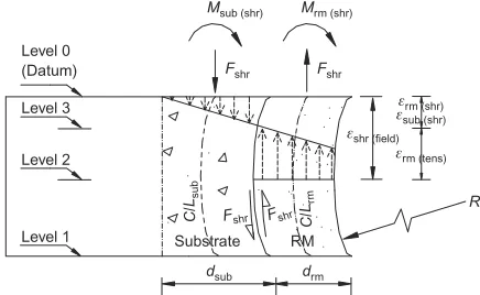
Figure 1 shows a cross-section through an unpropped compression member, repaired with a material with
Erm.Esub (the influence of steel reinforcement is
omitted for simplicity and to aid clarity). Immediately after application and before shrinkage begins, the repair material extends the full length of the repair patch, labelled level 0 to level 1. Assuming the substrate con-crete has a negligible elastic modulus (Erm0), the
repair material would shrink freely over a period of time from level 0 to level 2 in Fig. 1, displaying a free shrinkage strain, åshr(field). In an actual repair situation,
the substrate concrete has a stiffness which, in the case being considered, is less than the stiffness of the repair material (Esub,Erm). The repair material, therefore, is
prevented from deforming freely owing to the partial restraint provided by the substrate concrete. The
maxi-mum restraint will be at the substrate/repair material interface, but will gradually reduce as the distance from the interface increases owing to the action of the nor-mal compressive stresses acting within the zone of in-fluence (these stresses were not considered since the focus of the paper is the interfacial zone between the repair material and substrate concrete where the tensile cracking of the repair material is of critical concern in the design of patch repairs). Bending in the form of a circular arc will occur owing to the restrained shrinkage forces, Fshr, at the interface as shown in Fig. 1. A
tensile force is mobilised in the repair material and a compressive force acts in the substrate concrete.
The repair material is, therefore, assumed to shrink from level 0 to level 3 at the interface, årm(shr), Fig. 1.
The interfacial bond (assuming no slip) enables the substrate concrete to deform also from level 0 to level
3,åsub(shr). A tensile strainårm(tens) will, therefore, result
in the repair material and is equal to the difference between åshr(field) and årm(shr). A strain gradient will be
evident across the repair patch and the zone of influ-ence in the substrate concrete. The internal force sys-tem for both the repair material and substrate concrete can be reduced to longitudinal forces acting along each centroidal axis, Fshr (tension and compression
respec-tively) plus bending moments (Mrm(shr) and Msub(shr)),
Fig. 1. These bending moments will be produced by the eccentric interfacial forces, Fshracting atdsub/2 and drm/2 respectively from the centroidal axis of the
sub-strate concrete and the repair, that is Mrm(shr)¼
(Fshr)(drm/2) andMsub(shr)¼Fshr)(dsub/2).
The depth of concrete substrate (dsub) influenced by
shrinkage strain transfer is calculated from the radius of curvature of the deflection, R, which is caused by shrinkage restraint provided by the substrate to the repair patch.7SinceRis large compared with the
cross-section dimensions of the zone of influence and repair patch, it can therefore be taken as the same for both from elastic theory of bending
1
Rrm¼
1
Rsub
(1)
Equation (1) can be re-written in the form
Msub(shr)
EsubIsub ¼
Mrm(shr)
ErmIrm
(2)
Substituting for Mrm(shr)¼(Fshr)(drm/2), Msub(shr)¼
(Fshr)(dsub/2), Isub¼[b(1/12)d3sub] and Irm¼[b(1/12) d3
rm] and expanding the second moment of area terms
in equation (2) gives
Fshr(dsub=2) Esub[b(1=12)d3sub]
¼ Fshr(drm=2)
Erm[b(1=12)]d3rm
(3)
Simplifying equation (3) gives
d2sub¼d2rmErm Esub
(4)
Level 0 (Datum)
Level 3
Level 2
Level 1
Msub (shr) Mrm (shr)
F
shr Fshr
C
/
Lsub
Substrate RM Fshr Fshr /C Lrm
d
sub drm
R
åshr (field)
årm (shr)
årm (tens)
[image:4.595.45.263.594.728.2]åsub (shr)
Replacing Erm/Esub with m in equation (4) and
simpli-fying, the depth of substrate concrete,dsub, affected by
the transfer of shrinkage strain can be obtained from
dsub ¼drmpffiffiffiffim (5)
Referring to Fig. 1, the perpendicular distance between the forces Fshris 12(drm+dsub). The couple produced by
these forces must, for equilibrium, balance the sum of the moments in the repair and substrate materials. Thus
Fshr
2 (dsubþdrm)¼Msub(shr) ¼Mrm(shr) (6)
From the elastic theory of bending, Msub(shr)¼
(EsubIsub)/R andMrm(shr)¼(ErmIrm/R), whereR¼radius
of curvature and Isub and Irm are as given in equation
(3) (Fig. 1). Therefore, equation (6) can be written as
Fshr
2 (dsubþdrm)¼
EsubIsub
R þ
ErmIrm
R (7)
Rearranging equation (7) gives
Fshr¼2
EsubIsubþErmIrm dsubþdrm
1
R (8)
The only unknowns in equation (8) are the force due to shrinkage, Fshr, and the radius of curvature caused by
bending,R.
A second relationship was obtained by considering the strain compatibility of the two materials (repair and substrate) at the interface. These strains are made up of three components
(a) the elastic strain due to the longitudinal forces,Fshr
(b) the elastic strains due to the momentsMsub(shr) and
Mrm(shr)
(c) the free shrinkage of the repair material in the field
åshr(field).
Creep strains in the repair material are neglected at this stage but are considered later.
With regard to the elastic strains due to the direct shrinkage force, Fshr, the strains in the substrate
con-crete and repair material are obtained from å¼ó/E, therefore
åsub(dir)¼
Fshr bdsubEsub
(9)
and
Erm(dir)¼
Fshr bdrmErm
(10)
The elastic strains at the substrate/repair interface due to the moments Msub(shr) and Mrm(shr) are determined
from the elastic theory of bending. It can be shown that
ósub(bend)¼
dsubEsub
2R (11)
and
órm(bend)¼
drmErm
2R (12)
Dividing equations (11) and (12) by the elastic modulus of the respective material gives the strain in each mat-erial, åsub(bend)¼dsub=2R and årm(bend)¼drm/2R
respec-tively.
At the common interface between the repair material and substrate concrete, the net strain in the substrate concrete is equal to net strain in the repair material. Therefore
Fshr bdsubEsub
¼dsub 2R
¼åshr(field)
Fshr bdrmErm
drm 2R (13)
Equation (13) can be rearranged to give
Fshr¼
åshr(field)[(1=2R)(dsubþdrm)]
b
1
dsubEsubþ
1
drmþErm
(14)
Equations (8) and (14) can be solved to determine the only unknowns FshrandR. Hence, the compressive
stress at the interface of the substrate concrete due to a transfer of shrinkage strain from the stiffer repair mat-erial can be determined as
ósub(shr)¼
Fshr b ffiffiffiffi
m
p
drm¼
Esubpffiffiffiffimdrm
2R (15)
Similarly, the tensile stress in the repair material (at the interface) can be obtained from
órm(shr)¼
Fshr bdrm
Ermdrm
2R (16)
For simplicity, the above approach does not take creep into account. This provides a significant over-estimation of tensile stress by a factor of about two (see section on ‘validation’, below) compared with analysis including creep data.7 However, a more
accu-rate estimation of stress can be made by replacing Erm
(equation (16)) with an effective elastic modulus,
Erm(eff ) based on creep data, which accounts for stress
relaxation due to creep. Details of the procedure are given in the section on creep, below.
Semi-empirical procedure
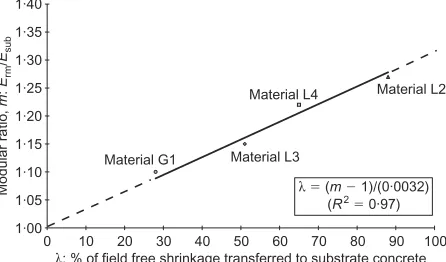
Substrate concrete. The semi-empirical procedure estimates interfacial stresses using an empirical rela-tionship between the modular ratio (m) of the repair material and substrate concrete and the percentage of shrinkage strain (º) transferred to the substrate con-crete. m¼Erm/Esub where Erm is the 28-day
compres-sive elastic modulus of the repair material and Esub is
for shrinkage strain transfer to the substrate concrete was obtained from field investigations on in situ repairs to highway structures whose details are given elsewhere.5 The resulting linear relationship given in
Fig. 2 shows that a higher m leads to greater transfer of shrinkage strain from the repair to substrate con-crete (at the interface). Optimum transfer is achieved at m1.32. The percentage of shrinkage strain trans-fer (º) for any repair material with 1.0<m<1.32 can be obtained from the transposed equation of the straight line in Fig. 2
º¼ m1
0:0032(%) (17) The strain transferred to the substrate concrete,åsub(shr),
can be obtained by substituting º¼[åsub(shr)=åshr(field)]
(100) into equation (17) to give
åsub(shr)¼
m1 0:32
åshr(field) (18)
whereåshr(field)is the free shrinkage of the in situ repair
patch in the field.
The section of this paper dealing with properties of repair material outlines the procedure to convert labora-tory data on free shrinkage of the repair materials,
åshr(lab), to corresponding field data on free shrinkage
åshr(field), by accounting for differences in temperature,
relative humidity and volume/surface. The interfacial compressive stress in the substrate concrete is given by
ósubs(shr)¼[åsub(shr)](Esub) (19)
This compressive stress induced by the restrained shrinkage of the repair material is assumed to cause no creep (and hence no creep relaxation) of the substrate concrete since
(a) in a repair situation, the concrete substrates have typically been under service load over long periods (e.g. over 30 years) and creep has practically ceased
(b) the compressive stresses induced in the substrate concrete due to restrained shrinkage of the repair
patch are small (typically,4 N/mm2) yielding
very low stress/strength ratios of creep loading.
Repair material. The tensile strain in the repair material, årm(tens), is the difference between its field
free shrinkage, åshr(field), and the shrinkage strain
transferred to the substrate concrete åsub(shr), given by
equation (18). årm(tens) can be estimated by modifying
equation (18) to give
årm(tens) ¼
1(m1) 0:32
åshr(field) (20)
The interfacial tensile stress due to the restraint to shrinkage in the repair material is therefore
órm(shr)¼[årm(tens)](Erm) (21)
Properties of repair material—conversion
of laboratory/material suppliers’ data to
field data
Introduction
The free shrinkage of a repair material determined in the laboratory under controlled conditions, åshr(lab), will
differ from the in situ free shrinkage of the repair material in the field, åshr(field). To enable the prediction
of interfacial stress from the procedures presented in this paper, the laboratory data are related to site condi-tions through the use of conversion factors (â) that take into account the difference in volume/surface ratios, temperature and relative humidity between the in situ and laboratory conditions.
As an illustration, an example is provided to convert the laboratory free shrinkage, creep and elastic modulus data to their equivalent in situ values in a real repair patch. The example is based on an in situ repair patch in a bridge structure investigated previously7 where a repair material, labelled L4, was used. Basic properties of the material L4 were determined by standard labora-tory testing and curing at 208C, 55%RH. The dimen-sions of the test specimens were 50031003100 mm. The 28-day elastic modulus and the 100-day free shrinkage values were 29.1 kN/mm2 and 782
micro-strain respectively.8 Free shrinkage
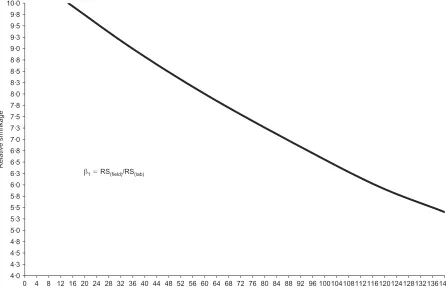
Volume/surface ratio. A higher volume/surface (v/s) ratio will lead to lower shrinkage and vice versa.9–11 This was accounted for by applying the nonlinear relationship between relative shrinkage and v/s ratios for concrete as shown in Fig. 3.12 External exposed surfaces only are used to calculate the sur-face area of the repair patches, the sursur-face bonded to the substrate concrete is neglected. The v/s ratio is calculated for both the laboratory test specimen and the field repair patch, thus the relative shrinkage
1·00 1·05 1·10 1·15 1·20 1·25 1·30 1·35 1·40
ë: % of field free shrinkage transferred to substrate concrete Material L2 Material L4
Material L3 Material G1
Modular r
a
tio
,
m
:
Erm
/
Esub
0 10 20 30 40 50 60 70 80 90 100
ë 5 (m2 1)/(0·0032) (R2
[image:6.595.45.268.572.703.2]5 0·97)
(RS) of the two can be estimated from Fig. 3. The v/s conversion factor (denoted â1) is given by
â1¼
RS(field)
RS(lab)
(22) The field repair patch of repair material L4 meas-ured 1500315003130 mm, whereas the laboratory specimen used for free shrinkage measurements had the dimensions 50031003100 mm. The volumes, therefore, of the field patch repair and laboratory speci-men are 292.53106mm3 and 53106mm3
respec-tively, whereas the corresponding exposed surface areas are 2.253106mm2 and 0.223106mm2. The
result-ing v/s ratios are 130 for the field patch repair and 22.7 for the laboratory specimen. Therefore, using the rela-tionship in Fig. 3 gives the values of RS(field)
5.75 mm and RS(lab)9.60 mm. Hence, from
equa-tion (22),â1¼5.75/9.60¼0.6.
Temperature. Shrinkage was adjusted on the basis that a 18C fall in site temperature relative to the control laboratory temperature results in a 1% de-crease in the free laboratory shrinkage12 as shown in Fig. 4. The factor for temperature correction is de-noted â2. The best-fit linear equation representing the
relationship in Fig. 4 is
â2¼0:01(T(field))þk (23)
whereT(field) is the temperature of the field repair patch
(8C) and k is a constant depending on the temperature
at which standard (laboratory) shrinkage testing is con-ducted. Values of krepresenting different test tempera-tures are listed in Fig. 4 and the case for 208C test temperature (k¼0.8) is plotted in the graph.
Referring to the practical example of the repair patch made with material L4 considered in this paper, the average field temperature of exposure was 108C, whereas the laboratory temperature was 208C. There-fore, from the graph in Fig. 4, the shrinkage modifica-tion factor,â20.9. Alternatively, using equation (23),
â2 can be calculated as k¼0.8; therefore, â2¼
0.01(10) + 0.8¼0.9.
Curing regime (relative humidity). Repair patches in the field can be cured in different ways. These are categorised into three main groups:13 Group one
in-volves keeping the surface of the repair patch moist by the use of ponding or continuous spraying; group two prevents moisture loss by covering the surface with polythene sheeting or leaving formwork in place; group three involves the use of curing compounds. Group one curing is most efficient but it is impracti-cal in a repair situation. Group three is not as effec-tive as group one but is more efficient than group two and has the advantage of needing no further supervision once the curing compound is applied. For this reason, and owing to their ease of application, curing compounds are the most commonly used tech-nique for curing repair patches. Most of the curing compounds come in two grades: a standard grade
4·0 4·3 4·5 4·8 5·0 5·3 5·5 5·8 6·0 6·3 6·5 6·8 7·0 7·3 7·5 7·8 8·0 8·3 8·5 8·8 9·0 9·3 9·5 9·8 10·0
Volume/surface ratio (v/s): mm
Relative shrinkage
136140 0 4 8 12 16 20 24 28 32 36 40 44 48 52 56 60 64 68 72 76 80 84 88 92 96 100104108112116120124128132
[image:7.595.94.540.56.343.2]â15 RS(field)/RS(lab)
having curing efficiency of 75% (relative humidity (RH) for curing¼75%) and a super grade having curing efficiency of 90% (tested in accordance with ASTM C30914 or AS 3799).15 The conservative value
of 75%RH is assumed for the purposes of calculation in this paper.
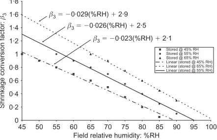
The effect of applying a curing compound to a repair patch on its free shrinkage in the field can be calcu-lated with reference to Fig. 5. The correction for RH differences between the laboratory and field conditions is based on a 2% decrease in shrinkage for each percent increase in RH to 70% and a 3% decrease in shrinkage for each percent increase in RH from 70% to 90%.12 This results in an approximately linear relationship be-tween the field relative humidity and the humidity correction factor â3, as plotted in Fig. 5. The general
equation representing the relationship is
â3¼ Æ(%RH)þç (24)
where %RH is the relative humidity in situ Fig. 5 gives the values of Æ and ç and for laboratory relative humidity of 45, 55 and 65%. Values at other RH can be obtained by linear interpolation.
The repair patch made with material L4 was cured in the field using a curing compound and polythene sheet-ing. It is assumed that this gives a RH of 75% for field curing. The laboratory shrinkage data were obtained at 55%RH. Hence, from the appropriate graph in Fig. 5, the conversion factor,â30.56.
Hence, the net field shrinkage of the repair patch made with repair material L4 can be calculated from the corresponding laboratory data of the material by applying the volume/surface, temperature and relative humidity correction factorsâ1,â2andâ3as follows:
Laboratory free shrinkage of material L4 at 100 days,åshr(lab)¼782 microstrain
Therefore
åshr(field)¼(â1)(â2)(â3)(åshr(lab))
¼(0:6)(0:9)(0:56)(782) ¼238 microstrain
Creep
Introduction. It was stated earlier that the incor-poration of creep in the analysis would provide the most accurate estimation of stress at the substrate interface. The following section outlines this proce-dure, which introduces the creep coefficient of the repair material in the analysis through the effective elastic modulus (creep) approach.
Elastic modulus. The elastic modulus of the repair material was determined under compression in the laboratory in accordance with BS 1881.8 The
cylind-rical test specimens measured 200 mm3100 mm dia-meter and were tested at 28 days’ age. However, since the repair material steadily develops its stiffness within the first month after application, and since creep relaxation is caused by restrained shrinkage tensile stresses, the 28-day compressive elastic modu-lus is converted to early-age tensile values by apply-ing a conversion factor â4(t) (Fig. 6). â4(t) is
determined on the following basis.
(a) The elastic modulus of a repair material at 7, 14 and 21 days equals 65, 85 and 96% of the 28-day value respectively.16
(b) The tensile elastic modulus of the repair material is approximately 9% lower than the compressive
0·8 0·85 0·9 0·95 1 1·05 1·1 1·15 1·2
Shrinkage conversion factor:
â2
6 8 10 12 14 16 18 20 22 24 26 28 30 Field temperature, T(field): °C
â25 0·01 (T(field)) 1 0·8
(@ T
(lab)5 20 °C)
Lab temp: (°C)
20 18 16 14 12 10
k
[image:8.595.44.266.55.190.2]0·80 0·82 0·84 0·86 0·88 0·90
Fig. 4. Shrinkage conversion factorâ2for temperature
0 0·2 0·4 0·6 0·8 1 1·2 1·4 1·6 1·8
Field relative humidity: %RH
Stored @ 45% RH Stored @ 55% RH Stored @ 65% RH Linear (stored @ 45% RH) Linear (stored @ 65% RH) Linear (stored @ 55% RH)
Shrinkage conversion factor:
â3 â3520·029(%RH) 1 2·9
â3520·026(%RH) 1 2·5
â3520·023(%RH) 1 2·1
45 50 55 60 65 70 75 80 85 90 95 100
Fig. 5. Shrinkage conversion factorâ3for relative humidity
0·0 0·1 0·2 0·3 0·4 0·5 0·6 0·7 0·8 0·9 1·0
Age in days: t
Elastic modulus conversion factor:
â4(
t
)
0 2 4 6 8 10 12 14 16 18 20 22 24 26 28 30 32 34 36
â4(t)5 0·24ln(t) 1 0·14
2 <t> 28 days
â4(t)5 0·94
t> 28 days
[image:8.595.289.509.580.721.2]Log. (developing Erm) Developing Erm
[image:8.595.46.267.585.728.2]value17 which is generally provided by the
manu-facturers’ data sheets.
(c) The tensile elastic modulus is used to calculate tensile stress by restrained shrinkage of the repair patch.
This information is represented graphically in Fig. 6 and the following best-fit equation is obtained
â4(t)¼0:24ln(t)þ0:14 (25)
wheretis the age of the repair patch in the range 2 to 28 days. The relationship in Fig. 6 yields a constant value for â4(t)0.94 at t>28 days, reducing to
ap-proximately 0.3 at 2 days. The early-age tensile elastic modulus (Erm(t)) at time t days is, therefore, obtained
from
Erm(t)¼(Erm)(â4(t)) (26)
where Erm is the 28-day elastic modulus determined
under compression in accordance with BS 18818 and
â4(t) is obtained from Fig. 6 (or equation (25)).
Influence of creep on stiffness. The effect of creep is accounted for in the creep approach by determining the effective elastic modulus of the repair material, Erm(eff ),t, from the following expression.18
Erm(eff ),t ¼ Erm(t)=(1 þ j) (27)
whereErm(t) is the elastic modulus of the repair
materi-al at time (equation (26)) andjis the creep coefficient
which is defined as
j¼ creep strain
instantaneous elastic strain (28) The compressive creep strain of repair materials is obtained by standardised testing19 and is assumed to
equal tensile creep at the same stress/strength ratios.20–22 Since the tensile stress/strength ratio of the
repair material at the interface of the substrate concrete varies considerably within a steadily shrinking repair patch, an average stress/strength ratio of 30% was em-ployed to determinej. It will be shown below that the
actual tensile stress/strength ratio in a repair patch (at the interface) varies considerably. Higher tensile stress/ strength ratios (than 30%) would lead to relatively higher creep and higher relaxation of tensile stress, thereby providing a further factor of safety for crack control.
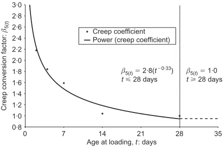
It is well established that cementitious materials ex-hibit more creep at early ages of loading. Fig. 7 shows the relationship between â5(t) and the age at which
creep specimens are loaded, where
â5(t) ¼
creep cofficient of specimens loaded at early age (,28 days)
creep coefficient of specimens loaded at 28 days age
(29)
The values of â5(t) for loading at 2, 4, 7, 14 and 28
days are plotted and the best-fit curve produced. Be-yond 28 days age of loading, â5(t) remains unity.23 At t<28,â5(t) is given by the expression
â5(t) ¼ 2:8(t0
:33
) (30)
where t is the age of the repair material in days when creep loading is applied. Thus, the creep coefficient at any aget,j(t), is obtained from
j(t) ¼ (j)(â5(t)) (31)
j is obtained from equation (28) and â5(t) is obtained
from Fig. 7 (or equation (30)). The effective elastic modulus, Erm(eff ), at t<28 is, therefore, obtained by
modifying equation (27) to take account of the elastic modulus–age relationship which gives factor (â4(t))
and the effect of early age loading on creep which gives factor â5(t). The resulting expression for Erm(eff ),
at timetis given by
Erm(eff ),t¼(Erm)(â4(t))=[1þ(j)(â5(t))] (32)
With regard to the example of the field repair patch made with repair material L4, the restrained shrinkage strain transfer occurs over approximately a three-month period,5 hence t>28 days. Referring to the graph in
Fig. 6, â4(t)0.94 and â5(t) 1.0 from the graph in
Fig. 7. The creep coefficient,j(equation (28)), for this
material is 0.89 from laboratory tests (jwas not
avail-able from the repair material manufacturer’s literature). Therefore, from equation (32), the effective elastic modulus att.28 days is
Erm(eff ),t>28 ¼(29:1)(0:94)=[1þ(0:89)(1:0)]
¼14:5 kN=mm2
Validation
Interfacial stresses
A summary of the interfacial stresses calculated in repair patches of bridge elements, made with four
re-0·8 1·0 1·2 1·4 1·6 1·8 2·0 2·2 2·4 2·6 2·8 3·0
Age at loading, t: days
Creep conversion factor:
â5(
t
)
0 7 14 21 28 35
â5(t)5 2·8(t2 0·33
) t< 28 days
â5(t)5 1·0
t> 28 days Creep coefficient
[image:9.595.329.552.54.201.2]Power (creep coefficient)
Fig. 7. Elastic modulus conversion factorâ5( t)for early-age
pair materials (L4, L3, L2 and G1) are given in Table 1. The material identification is given in column 1. Stresses are calculated at both the substrate concrete and repair material interface (‘subs’ and ‘rm @ inter-face’ respectively, Table 1, column 2). Stresses modi-fied by the creep coefficient (creep approach) are given in column 3 and are calculated at arbitrary ages of 14, 90 and 182 days after application (0.5, 3 and 6 months respectively). This is the most rigorous method of stress analysis presented and leads to the highest accuracy. The interfacial stresses at these ages are used to illus-trate the variation in tensile stress/strength ratios that occur after application of patch repairs (further details are given below). Interfacial stresses calculated by the elastic approach (i.e. using Erm and not Erm(eff )) at age
182 days only are presented in column 4 and are consistently higher than those predicted by the creep approach at 182 days (column 3 and Fig. 8). Referring to columns 3, 4 in Table 1 and Fig. 8, the rm @ inter-face (creep approach) stresses at age 182 days are approximately half those of the elastic approach. It is recommended, therefore, to use the elastic approach in design of patch repairs for two reasons. First, creep properties of repair materials are generally unavailable in manufacturers’ literature and second, the elastic ap-proach has an in-built factor of safety of approximately two.
The substrate concrete stresses are marginally higher using the elastic approach (compare subs stresses at 182 days in columns 3 and 4 in Table 1 and Fig. 8). The prediction of compressive stress in the substrate concrete is less important for the design of a patch repair since the magnitude of compressive stress in a repair patch is insignificant relative to the compressive strength of a typical repair material which exceeds 30 N/mm2 at 28 days. The semi-empirical method (Fig.
8) provides a reasonable estimation of interfacial stres-ses but the more rigorous creep approach is preferred to ensure higher accuracy.
Tensile stress/strength ratios
Information on the direct tensile strength of repair materials is largely unavailable in the data sheets, although indirect tensile properties in the form of mod-ulus of rupture and cylinder splitting strength are some-times available. The tensile strength of the four repair materials under consideration is estimated from a rela-tionship between the direct tensile strengths and cube crushing strength for concrete mixes.24 All repair
mat-erials are cementitious based and further details can be obtained elsewhere.5
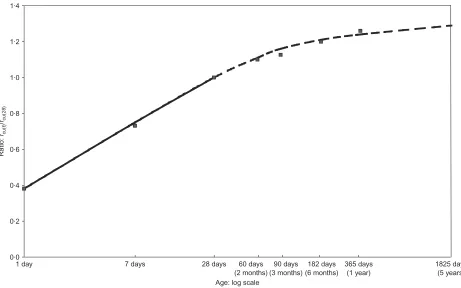
The ratio of average compressive strength for a num-ber of repair materials at any aget,fcu(t),, in relation to
the average 28-day compressive strength,fcu(28), is given
in Fig. 9. This relationship is based on the average compressive strength (up to age 28 days) of the four repair materials considered in this paper and is extra-polated thereafter based on a Portland cement
con-crete17 for the purpose of this paper. It is used to
provide an estimation of the compressive strengths of the repair materials at 14, 90 and 182 days after appli-cation. Referring to Fig. 9, at age 14 days, the ratio
fcu(14)/fcu(28) is approximately 0.88. fcu(90)=fcu(28) is
ap-proximately 1.16 at age 90 days and at 182 days the ratio fcu(182)/fcu(28) is approximately 1.2. The 28-day
cube strengths listed in column 6, Table 1, obtained from the manufacturers’ literature, are therefore multi-plied by 0.88, 1.16 and 1.2 to give an estimation of the compressive strength at 14, 90 and 182 days respec-tively (Table 1).
An estimation of the tensile strength at the selected ages is given in column 7. It is based on a relationship between compressive and direct tensile strengths for concrete which is given by
ót(t) ¼ 0:27fcu(t)0
:59
(33) where ót(t) is the estimated tensile stress at time t24
(t¼14, 90 and 182 days).
The estimated tensile strengths at 14, 90 and 182 days age are listed in column 7 of Table 1. The tensile stress of the repair material at the three ages is listed in column 3. The resulting tensile stress/strength ratios at the repair material interface are given in column 8. It is clear from column 8 that the tensile stress/strength ratios are lower at early ages (average 19% at 14 days) but increase with time to average 49% at 14 days and 48% at 182 days. These figures indicate that at early ages the elastic modulus and shrinkage properties of the repair materials are developing rapidly while creep relaxation is also maximum (see â5(t), Fig. 7), hence
high creep is offsetting the restrained shrinkage stres-ses. At later stages (90 and 182 days), the elastic modulus and shrinkage properties of the repair materi-als have stabilised and relaxation of stress due to high creep rates no longer applies. Higher stresses and con-sequently, higher tensile stress/strength ratios result but the magnitudes are insufficient to cause tensile crack-ing due to restrained shrinkage.
To ensure that the repair patch remains crack-free, the tensile stress/strength ratio (after creep relaxation) must remain below 100% (or 50% to apply a factor of safety of 2). This can be achieved through designing the repair patch in accordance with the recommenda-tions given in this paper.
Conclusions
The following conclusions are based on the informa-tion presented in the paper.
(a) Laboratory shrinkage of repair materials, åshr(lab),
can be related to in situ shrinkage in the field,
åshr(field), by applying three conversion factors from
Table 1. Validation of procedures
Column 1 Column 2 Column 3 Column 4 Column 5 Column 6 Column 7 Column 8
Material Location Creep approach*
(equations (15) and (16)):
N/mm2
Elastic approach† (equations (15)
and (16)):
N/mm2
Semi-empirical approach† (equations (19) and
(21)): N/mm2
Estimated cube strength,fcu(t)‡
(Fig. 9): N/mm2
Estimated tensile strength,ót(t)
(equation (33)): N/mm2
tensile stress, column 3
tensile strength, columnn 7: %
14 days
90 days
182 days
182 days
182 days
28 days§
14 days
90 days
182 days
14 days
90 days
182 days
14 days
90 days
182 days
L4 subs +1.4 +2.4 +2.5 +3.0 +3.9 60 53 70 72 2.8 3.3 3.4 27 48 47
rm@interface 0.7 1.6 1.6 3.3 2.1
L3 subs
rm@interface
+0.4
0.2
+2.0
1.1
+2.0
1.1
+2.6
2.8
+2.4
3.0
35 31 41 42 2.0 2.4 2.4 9 46 46
L2 subs
rm@interface
+1.0
0.5
+1.4
0.8
+1.4
0.8
+1.7
1.9
+2.8
0.6
60 53 70 72 2.8 3.3 3.4 13 24 24
G1 subs
rm@interface
+2.1
1.1
+4.0
2.6
+4.0
2.6
+4.7
5.0
+3.1
6.8
60 53 70 72 2.8 3.3 3.4 27 79 76
19 49 48
Averages
* (Erm(eff ),t)(årm(tens))
† (Erm))(årm(tens))
‡ Strength extrapolated from manufacturers’ 28-day strengths18
§ Manufacturers’ 28-day strengths
Flaherty
and
Mangat
Mag
azine
of
Concr
ete
Resear
ch
,
2006,
58
,
correction, â2 for temperature correction and â3
for relative humidity correction.
(b) The interfacial compressive stress in the substrate concrete due to the transfer of shrinkage from the repair material can be analytically determined from
ósub(shr)¼
Fshr b ffiffiffiffi
m
p
drmþ
Esubpffiffiffiffimdrm
2R
(c) The interfacial elastic tensile stress in the repair material, when relaxation due to creep is neglected, can be analytically determined from
órm(shr) ¼
Fshr bdrm
Ermdrm
2R
(d) The interfacial relaxed tensile stress in the repair material, when the effects of creep are considered,
can be analytically determined by replacing Erm
withErm(eff ),tas follows
órm(shr)¼
Fshr bdrm
Erm(eff ),t(drm)
2R
where
Erm(eff ),t ¼ (Erm)(â4(t))=[1 þ (j)(â5(t))]
(e) The interfacial compressive stress in the substrate concrete due to the transfer of shrinkage from the repair material can be semi-empirically determined
fromósub(shr)¼(åsub(shr))(Esub).
(f) The interfacial tensile stress in the repair material can be semi-empirically determined from órm(shr)
¼(årm(tens))(Erm).
(g) The tensile stress/tensile strength ratios for repair materials specified in accordance with the recom-mendations given in this paper are low in the early ages after application owing to high creep and low-er elastic modulus and shrinkage. These ratios in-crease over time but should remain below 100% in order to prevent restrained shrinkage cracking (or 50% if a factor of safety of 2 is to be assumed).
Acknowledgements
This paper is based on a LINK TIO funded project entitled ‘Long-term performance of concrete repair in highway structures’. The partners in the project were
28
26
24
22
0 2 4 6
Repair patch material Creep Elastic rm @ interface (182 days)
subs (182 days)
(T
ension)
Interfacial stresses: MP
a
(Compression) L4 L3 L2 G1
L4 L3 L2 G1
[image:12.595.45.270.55.186.2]Semi-empirical
Fig. 8. Comparison of stresses at 182 days after application
0·0 0·2 0·4 0·6 0·8 1·0 1·2 1·4
R
a
tio:
fcu(
t
)
/
fcu(
28
)
1 day 7 days 28 days 60 days
(2 months) 90 days (3 months)
182 days (6 months)
365 days (1 year)
1825 days (5 years) Age: log scale
[image:12.595.46.507.442.730.2]Sheffield Hallam University, V.A. Crookes (Contracts) Ltd, Flexcrete Ltd, M. J. Gleeson Group plc. The con-tribution of all project partners, the former Department of Transport, the Highways Agency and local authori-ties (Nottinghamshire County Council, Sheffield City Council) are gratefully acknowledged.
References
1. EmmonsP. H.,VaysburdA. M. andMcDonaldJ. E. Concrete
repair in the future turn of the century—any problems?Concrete
International,1994,16, No. 3, 42–49.
2. Mangat P. S. and O’Flaherty F. J. Factors affecting the efficiency of repair to propped and unpropped bridge beams.
Magazine of Concrete Research, 2000,52, No. 4, 303–319. 3. MangatP. S. andO’FlahertyF. J. Serviceability
character-istics of flowing repairs to propped and unpropped bridge
struc-tures.Materials and Structures, 1999,32, No. 223, 663–672.
4. MangatP. S. andO’Flaherty, F. J. Influence of elastic mod-ulus on stress redistribution and cracking in repair patches.
Cement and Concrete Research, 2000,30, No. 1, 125–136. 5. MangatP. S. andO’FlahertyF. J. Long-term performance of
high stiffness repairs in highway structures.Magazine of
Con-crete Research, 1999,51, No. 5, 325–339.
6. O’FlahertyF. J. andMangatP. S. Recommendations for the
European Prestandard for concrete repair.RILEM 2nd
Interna-tional Workshop on Life Prediction and Aging Management of Concrete Structures, Paris, France, 5–6 May 2003, pp. 237–245.
7. MangatP. S. and O’Flaherty F. J. Analysis of interfacial
shrinkage stress in patch repairs. Magazine of Concrete
Re-search, 2003,56, No. 7, 375–386.
8. British Standards Institution. BS 1881.Method for deter-mination of static modulus of elasticity in compression, Part
121. BSI, London, 1983.
9. MangatP. S. andLimbachiyaM. K. Repair materials proper-ties which influence long-term performance of concrete
struc-tures. Construction and Building Materials, 1995, 9, No. 2,
81–90.
10. MangatP. S. andLimbachiyaM. K. Repair material
proper-ties for effective structural application.Cement and Concrete
Research,1997,27, No. 4, 601–617.
11. DectorM. H. and LambeR. W. New materials for concrete
repair–development and testing. The Indian Concrete Journal,
1993,67, No. 10, 475–480.
12. KongF. K. andEvansR. H.Reinforced and Prestressed
Con-crete, 3rd edn. Van Nostrand Reinhold, New York, 1987. 13. Curing, Cement and Concrete Association of New
Zeal-and. Site Concreting, SC 4 (www.holcim.com/Upload/NZ/ Publications/ECS_Curing%20of%20Concrete.pdf).
14. American Society for Testing Materials.Standard specifi-cation for liquid membrane-forming compounds for curing con-crete. ASTM C 309–97. ASTM, Philadelphia, PA, USA, 1997. 15. Australian Standard.Liquid membrane-forming compounds
for concrete. Standards Australia, Sydney, 1998, AS 3799–1998. 16. PinelleD. J. Curing stresses in polymer modified repair
mor-tars. Cement, Concrete and Aggregates, CCAGDP, 1995, 17,
No. 2, 195–200.
17. Brooks J. J. and Neville A. M. A comparison of creep, elasticity and strength of concrete in tension and in
compres-sion.Magazine of Concrete Research, 1978, Vol.29, No. 100,
131–141.
18. MosleyW. H. andBungeyJ. H.Reinforced Concrete Design,
4thedn. McMillan, London, 1990, p. 362.
19. Illston J. M. and Pomeroy C. D. Recommendations for a standard creep test.Concrete, 1975,9, No. 12, 24–25.
20. Illston J. M. The creep of concrete under uniaxial tension.
Magazine of Concrete Research, 1965,17, No. 51, 77–84. 21. GlanvilleW. H. andThomasF. G.Further Investigations on
the Creep or Flow of Concrete under Load.Building Research Technical Paper No. 21. HMSO, London, 1939, pp. 5–8. 22. HansonJ. A.A 10-year study of creep properties of concrete.
United States Department of the Interior, Bureau of Reclama-tion, July 1953, Laboratory Report, No. SP-38.
23. Yuan Y. S. andMarosszekyM. Major factors affecting the
performance of structural repair.Proceedings of the ACI
Inter-national Conference on Evaluation and Rehabilitation of Con-crete Structures and Innovations in Design. ACI-SP128, Vol. 2. American Concrete Institute, Detroit, 1991, pp. 819–837. 24. Brooks J. J. and Neville A. M. A comparison of creep,
elasticity and strength of concrete in tension and in
compres-sion. Magazine of Concrete Research, 1977, 29, No. 100,
131–141.