Orcad
®
Capture
Copyright © 1985-2000 Cadence Design Systems, Inc. All rights reserved.
Trademarks
Allegro, Ambit, BuildGates, Cadence, Cadence logo, Concept, Diva, Dracula, Gate Ensemble, NC Verilog, OpenBook online documentation library, Orcad, Orcad Capture, PSpice, SourceLink online customer support, SPECCTRA, Spectre, Vampire, Verifault-XL, Verilog, Verilog-XL, and Virtuoso are registered trademarks of Cadence Design Systems, Inc.
Affirma, Assura, Cierto, Envisia, Mercury Plus, Quickturn, Radium, Silicon Ensemble, and SPECCTRAQuest are trademarks of Cadence Design Systems, Inc.
Alanza is a service mark of Cadence Design Systems, Inc.
All other brand and product names mentioned herein are used for identification purposes only and are registered trademarks, trademarks, or service marks of their respective holders.
60-30-611
Second edition 31 May 2000
Cadence PCB Systems Division (PSD) offices PSD main office (Portland) (503) 671-9500
PSD Irvine office (949) 788-6080
PSD Japan office 81-45-682-5770
PSD UK office 44-1256-381-400
PSD customer support (877) 237-4911
PSD web site www.orcad.com
Contents
Contents iii
Before you begin xvii
Welcome . . . xvii
How to use this guide . . . xviii
Symbols and conventions . . . xviii
Related documentation . . . xix
Part One
Capture basics
Getting started 3
Chapter 1
Starting Capture . . . 3The Capture session frame . . . 4
The Capture work environment 5
Chapter 2
The project manager . . . 6Project manager folders . . . 6
Project manager tabs—File and Hierarchy . . . 9
Single view . . . 9
Flat and hierarchical designs . . . 10
Project manager pop-up menus . . . 10
The schematic page editor . . . 11
The part editor . . . 12
The programmer’s editor . . . 13
The session log . . . 14
The toolbar . . . 16
Displaying or hiding the toolbar . . . 18
The tool palettes . . . 19
Displaying or hiding a tool palette . . . 24
The status bar . . . 25
Left field . . . 25
Center field . . . 25
Right field . . . 25
Displaying or hiding the status bar . . . 26
Selecting and deselecting objects . . . 27
Grouping objects . . . 29
Editing properties . . . 30
Instance and occurrence properties . . . 31
Instance properties . . . 31
Occurrence properties . . . 31
The Browse spreadsheet editor . . . 32
The property editor . . . 35
The property editor window . . . 36
The property editor Filter menu . . . 40
Using the property editor . . . 43
The Package Properties spreadsheet editor . . . 46
Moving and resizing graphic objects . . . 48
Undoing, redoing, and repeating an action . . . 49
Using the Accessories menu . . . 51
Starting a project 51
Chapter 3
Creating new projects, designs, libraries, and VHDL files . . . 52Opening existing projects, designs, libraries, and VHDL files . . . 55
Working with files in a project . . . 57
Saving projects, designs, and libraries . . . 58
Closing a project . . . 59
Archiving a project . . . 61
Setting up your project 63
Chapter 4
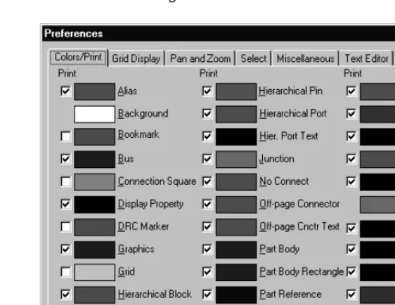
Defining your preferences . . . 65Defining colors/print options . . . 66
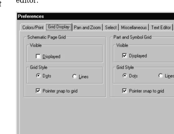
Controlling the grid . . . 68
Contents
Setting the schematic page size for new projects . . . 82
Defining the grid reference . . . 84
Defining the default hierarchy option for new projects . . . 86
Setting up compatibility with Orcad’s Schematic Design Tools (SDT) 87 Changing properties of existing projects . . . 88
Assigning fonts . . . 89
Defining hierarchy . . . 89
Using Capture with SDT . . . 89
Viewing design information . . . 90
Viewing and connecting to invisible power pins . . . 91
Changing properties of existing schematic pages . . . 92
Changing page size . . . 92
Setting up new grid references . . . 93
Viewing miscellaneous schematic page properties . . . 93
Printing and plotting 95
Chapter 5
Printing or plotting schematic pages . . . 96Printing or plotting parts or packages . . . 97
Printing the session log and text editor windows . . . 98
Previewing printer or plotter output . . . 99
Scaling printer or plotter output . . . 100
Special considerations for plotting . . . 101
Plotter pen colors . . . 101
Part Two
Creating designs
Design structure 105
Chapter 6
Flat designs . . . 106Hierarchical designs . . . 107
Simple hierarchical designs . . . 107
Complex hierarchies . . . 109
Connecting schematic folders and schematic pages . . . 110
Hierarchical blocks . . . 110
Hierarchical ports . . . 111
Hierarchical pins . . . 111
Off-page connectors . . . 112
An example: creating a simple hierarchy . . . 113
Placing parts . . . 118
Place Part dialog box . . . 121
Most Recently Used (MRU) part list . . . 124
Searching for parts . . . 125
Editing parts . . . 125
Placing and editing power and ground symbols . . . 128
Placing power and ground symbols . . . 128
Place Power and Place Ground dialog boxes . . . 130
Editing power and ground symbols . . . 131
Placing and editing no-connect symbols . . . 132
Placing no-connect symbols . . . 132
Editing no-connect symbols . . . 133
Placing and editing hierarchical blocks . . . 134
Placing hierarchical blocks . . . 134
Place Hierarchical Block dialog box . . . 136
Editing hierarchical blocks . . . 138
Placing and editing hierarchical ports and hierarchical pins . . . 139
Placing hierarchical ports . . . 139
Place Hierarchical Port dialog box . . . 140
Placing hierarchical pins . . . 141
Place Hierarchical Pin dialog box . . . 143
Editing hierarchical ports and hierarchical pins . . . 143
Placing and editing off-page connectors . . . 144
Placing off-page connectors . . . 144
Place Off-Page Connector dialog box . . . 146
Editing off-page connectors . . . 147
Placing and connecting wires and buses . . . 148
Placing wires . . . 149
Editing wires . . . 150
Moving wires . . . 151
Placing buses . . . 152
Editing buses . . . 153
Placing bus entries . . . 153
Editing bus entries . . . 154
Contents
Drawing arcs . . . 162
Drawing polylines and polygons . . . 163
Adding fill to an object . . . 164
Mirroring an object . . . 164
Rotating an object . . . 165
Moving an object . . . 165
Cutting an object . . . 165
Copying an object . . . 166
Pasting an object . . . 166
Deleting a selected object . . . 166
Placing a bitmap . . . 167
Placing text . . . 168
The text bounding box . . . 170
Deleting text . . . 170
Modifying text . . . 170
Finding text . . . 171
Replacing text . . . 172
Importing text . . . 172
Exporting text . . . 173
Character formatting . . . 173
About screen fonts . . . 174
Using macros 175
Chapter 9
Recording a macro . . . 177Playing a macro . . . 178
Configuring a macro . . . 179
Configure Macro dialog box . . . 180
Naming a macro . . . 183
Assigning a shortcut key to a macro . . . 185
Sample macros . . . 186
Changing your view of a schematic page 187
Chapter 10
Zooming . . . 188Zooming to a specified scale . . . 189
Other viewing options . . . 189
Moving to a new location . . . 192
Moving to an X, Y location . . . 192
Go To dialog box, Location tab . . . 193
Jumping to a specific grid reference . . . 194
Go To dialog box, Grid Reference tab . . . 194
Go To dialog box, Bookmark tab . . . 196
Displaying the grid and grid references . . . 197
Finding parts in a project . . . 198
Part Three Libraries and parts
About libraries and parts 201
Chapter 11
Libraries . . . 202Parts . . . 203
About part instances and part occurrences . . . 204
The design cache . . . 205
Primitive and nonprimitive parts . . . 208
Creating and editing parts 209
Chapter 12
Parts and packages: homogeneous or heterogeneous . . . 210Creating a new part . . . 211
Defining a part . . . 211
New Part Properties dialog box . . . 214
Attaching a schematic folder to a part . . . 216
Adding graphics, text, and IEEE symbols to a part . . . 217
Placing pins on a part . . . 218
Place Pin dialog box . . . 220
Place Pin Array dialog box . . . 225
About power and ground pins . . . 227
Displaying invisible power pins . . . 228
Editing an existing part . . . 229
Editing a part in a library . . . 229
Editing a part on a schematic page . . . 230
Editing part properties . . . 231
Default part properties . . . 232
Viewing parts in a package . . . 234
Editing parts in a package . . . 235
Editing part and package properties in the part editor . . . 236
Contents
Updating instances and occurrences . . . 246
Preparing to create a netlist 247
Chapter 14
Annotating . . . 247Annotate dialog box . . . 249
Updating properties . . . 251
Update Properties dialog box . . . 253
Update file format . . . 255
Checking for design rules violations . . . 256
Design Rules Check dialog box, Design Rules Check tab . . . . 259
Design Rules Check dialog box, ERC Matrix tab . . . 262
Sample Design Rules Check report . . . 263
Back annotating . . . 266
Back Annotate dialog box . . . 268
Swap file format . . . 269
Creating a netlist 271
Chapter 15
Using the Create Netlist tool . . . 271Netlist format files . . . 273
Netname resolution . . . 274
Creating reports 275
Chapter 16
Creating a bill of materials . . . 275Bill of Materials dialog box . . . 277
Include file format . . . 279
Creating a cross reference report . . . 280
Cross Reference Parts dialog box . . . 281
Exporting and importing schematic data 283
Chapter 17
Exporting and importing designs . . . 283Exporting designs . . . 284
Importing designs . . . 285
Exporting and importing properties . . . 286
Exporting properties . . . 286
Property file format . . . 288
Editing a property file . . . 288
Importing properties . . . 290
Generate a new part . . . 294
Update the pin numbers of an existing part . . . 297
Using Capture with Orcad Layout 299
Chapter 19
Preparing your Capture design for use with Layout . . . 301Creating a netlist for use in Layout . . . 303
Loading a new netlist into Layout . . . 304
Back annotating board information from Layout . . . 306
Forward annotating schematic data to Layout . . . 307
Cross probing between Capture and Layout . . . 308
Enabling intertool communication between Capture and Layout . . 308
Cross probing from Capture to Layout . . . 309
Cross probing from Layout to Capture . . . 310
General rules . . . 311
Using Capture with PSpice 313
Chapter 20
Overview . . . 313Specifying simulation model libraries . . . 314
Creating a design for PSpice A/D simulation . . . 315
Editing simulation models from Capture . . . 316
Adding and defining stimulus . . . 317
Placing stimulus sources . . . 317
Using the Stimulus Editor . . . 317
Setting up and running analyses . . . 318
Viewing results . . . 319
Viewing results as you simulate . . . 319
Using markers . . . 319
Configuring the display of simulation results . . . 320
Creating designs for PSpice simulation and board layout . . . 321
Handling unmodeled pins . . . 322
Displaying bias point information . . . 323
Displaying bias point values . . . 323
Glossary 325
Figures
Figure 1 Capture’s session frame . . . 4
Figure 2 New project manager window . . . 6
Figure 3 File tab . . . 9
Figure 4 Hierarchy tab . . . 9
Figure 5 Schematic page editor . . . 11
Figure 6 Part editor . . . 12
Figure 7 Programmer’s editor . . . 13
Figure 8 Session log . . . 14
Figure 9 Capture’s toolbar . . . 16
Figure 10 Schematic page editor tool palette . . . 19
Figure 11 Part editor tool palette . . . 22
Figure 12 The status bar . . . 25
Figure 13 Browse spreadsheet editor . . . 32
Figure 14 Property editor . . . 36
Figure 15 Package Properties spreadsheet editor . . . 46
Figure 16 Open project, design, and schematic page . . . 55
Figure 17 Open library . . . 56
Figure 18 Open VHDL file . . . 56
Figure 19 Colors/Print tab of the Preferences dialog box . . . 66
Figure 20 Grid Display tab of the Preferences dialog box . . . 68
Figure 21 Pan and Zoom tab of the Preferences dialog box . . . 69
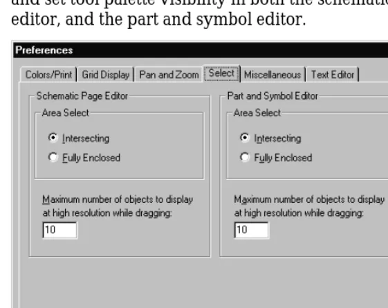
Figure 22 Select tab of the Preferences dialog box . . . 71
Figure 23 Miscellaneous tab of the Preferences dialog box . . . 73
Figure 24 Text Editor tab of the Preferences dialog box . . . 76
Figure 25 Fonts tab of the Design Template dialog box . . . 79
Figure 26 Title Block tab of the Design Template dialog box . . . 80
Figure 27 Title block . . . 81
Figure 28 Page Size tab of the Design Template dialog box . . . 82
Figure 29 Grid Reference tab of the Design Template dialog box . . . 84
Figure 30 Hierarchy tab of the Design Template dialog box . . . 86
Figure 33 Miscellaneous tab of the Schematic Page Properties dialog box . . . 93
Figure 34 An abstract representation of a simple hierarchy. . . . 107
Figure 35 A simple hierarchical design, as seen in the project manager . . . 108
Figure 36 An abstract representation of a complex hierarchy . . . 109
Figure 37 A complex hierarchical design, as seen in the project manager . . . 109
Figure 38 Schematics before hierarchy . . . 113
Figure 39 Schematics with hierarchy . . . 113
Figure 40 Schematics carrying a net . . . 114
Figure 41 Connectivity across pages in a schematic . . . 114
Figure 42 Schematic with power and ground symbols . . . 115
Figure 43 Part editor in package view . . . 117
Figure 44 Part editor in part view . . . 118
Figure 45 Place Part dialog box . . . 121
Figure 46 Property editor with filter set to Capture . . . 126
Figure 47 Power and ground symbols in CAPSYM.OLB . . . 128
Figure 48 Place Power dialog box . . . 130
Figure 49 Hierarchical block . . . 134
Figure 50 Place Hierarchical Block dialog box . . . 136
Figure 51 Hierarchical ports in CAPSYM.OLB . . . 139
Figure 52 Place Hierarchical Port dialog box . . . 140
Figure 53 Place Hierarchical Pin dialog box . . . 143
Figure 54 Off-page connectors in CAPSYM.OLB . . . 144
Figure 55 Place Off-Page Connector dialog box . . . 146
Figure 56 Connectivity change warning . . . 151
Figure 57 Schematic page editor tool palette . . . 158
Figure 58 Part editor tool palette . . . 158
Figure 59 Configure Macro dialog box . . . 180
Figure 60 Location tab of the Go To dialog box . . . 193
Figure 61 Grid Reference tab of the Go To dialog box . . . 194
Figure 62 Bookmark tab of the Go To dialog box . . . 196
Figure 63 Replace Cache dialog box . . . 206
Figure 64 New Part Properties dialog box . . . 214
Figure 65 Place Pin dialog box . . . 220
Figure 66 Place Pin Array dialog box . . . 225
Figure 67 User Properties dialog box . . . 232
Figures
Figure 75 ERC tab of the Design Rules Check dialog box . . . 262
Figure 76 Back Annotate dialog box . . . 268
Figure 77 Create Netlist dialog box . . . 272
Figure 78 Bill of Materials dialog box . . . 277
Figure 79 Cross Reference Parts dialog box . . . 281
Figure 80 Export Design dialog box . . . 284
Figure 81 Import Design dialog box . . . 285
Figure 82 Export Properties dialog box . . . 287
Figure 83 Import Properties dialog box . . . 291
Figure 84 Generate Part dialog box . . . 295
Tables
Table 1 Tools on the Capture toolbar . . . 16
Table 2 Tools on the schematic page editor tool palette . . . 20
Table 3 Tools on the part editor tool palette . . . 22
Table 4 Capture’s macro subroutines . . . 183
Table 5 Valid shortcut keys . . . 186
Table 6 Pin shapes . . . 221
Table 7 Pin types . . . 222
Table 8 Capture tools overview . . . 245
Table 9 Updating instances or occurrences . . . 246
Table 10 Netlist format file types . . . 273
Table 11 Action on part or pin properties . . . 290
Table 12 Cross probing from Capture to Layout . . . 309
Before you begin
Welcome
Orcad family products offer a total solution for your core design tasks: schematic- and VHDL-based design entry; FPGA and CPLD design synthesis; digital, analog, and mixed-signal simulation; and printed circuit board layout. What’s more, Orcad family products are a suite of
applications built around an engineer's design flow—not just a collection of independently developed point tools. Orcad Capture is just one element in our total solution design flow.
How to use this guide
This guide is designed so you can quickly find the information you need to use Insert Product Name. To help you learn and use Insert Product Name efficiently, this manual is separated into the following sections:
• Part 1, Capture basics, includes how to get started with Capture; what you need to know about the Capture windows, editors, session log, the toolbar and tool palettes, and general Capture concepts; how to start and set up a project; and printing and plotting.
• Part 2, Creating designs, discusses design structure; placing, editing, and connecting parts and symbols; adding and editing graphics and text; using macros, and changing your schematic page view.
• Part 3, Libraries and parts, tells you about libraries and parts, and how to create and edit parts.
• Part 4, Processing your design, provides an overview of the processing tools; creating a netlist and reports; exporting and importing schematic data; generating a part; and using Capture with Orcad Layout and PSpice.
Symbols and conventions
Our printed documentation uses a few special symbols and conventions.
Notation Examples Description
C+r Press C+r. Means to hold down the C key while
pressing r.
How to use this guide
Related documentation
In addition to this guide, you can find technical product information in the online help, the online interactive tutorial, online books, and our technical web site, as well as in other books. The table below describes the types of technical documentation provided with Insert Product Name.
Monospace font In the Part Name text box, type PARAM. Text that you type is shown in
monospace font. In the example, you type the characters P, A, R, A, and M.
UPPERCASE In Capture, open CLIPPERA.DSN. Path and filenames are shown in
uppercase. In the example, you open the design file named CLIPPERA.DSN. Italics In Capture, save design_name.DSN. Information that you are to provide is
shown in italics. In the example, you save the design with a name of your choice, but it must have an extension of .DSN.
This documentation component . . . Provides this . . . This guide—
Orcad Capture User’s Guide
Online help Comprehensive information for understanding and using the features available in Insert Product Name.
You can access help from the Help menu in Insert Product Name by choosing the Help button in a dialog box, or by pressing 1. Topics include:
• Explanations and instructions for common tasks.
• Descriptions of menu commands, dialog boxes, tools on the toolbar and tool palettes, and the status bar.
• Error messages and glossary terms.
• Reference information.
• Product support information.
You can get context-sensitive help for a error message by placing your cursor in the error message line in the session log and pressing 1.
Online interactive tutorial A series of self-paced interactive lessons. You can practice what you’ve learned by going through the tutorial’s specially designed exercises that interact directly with Insert Product Name. You can start the tutorial by choosing Learning Insert Product Name from the Help menu. Online Orcad Capture User’s Guide An online, searchable version of this guide, available when
choosing Online Manuals from the Orcad family program group (on the Start menu).
Online Insert Product Name quick reference Concise descriptions of the commands, shortcuts, and tools available in Insert Product Name, available when choosing Online Manuals from the Orcad family program group (on the Start menu).
How to use this guide
Orcad family customer support at www.orcad.com/technical/technical.asp
An Internet-based support service available to customers with current support options. A few of the technical solutions within the customer support area are:
• The Knowledge Base, which is a searchable database containing thousands of articles on topics ranging from schematic design entry and VHDL-based PLD design to PCB layout methodologies. It also contains answers to frequently asked questions.
• The Knowledge Exchange, which enables you to share information and ideas with other users and with our technical experts in a real-time online forum. You can submit issues or questions for open discussion, search the Knowledge Exchange for information, or send email to another participant for one-on-one communication. A list of new postings will appear each time you visit the Knowledge Exchange, providing you with a quick update of what’s been discussed since your last visit.
• The Technical Library, which contains online customer support information that you can search through by category or product. You can find product manuals, product literature, technical notes, articles, samples, books, and other technical information. Additionally, technical information can be obtained through SourceLink, which is an online customer support information service for users of Cadence software other than Capture, Component Information System (CIS), Express, Layout, or PSpice.
• The Support Connection, which allows you to choose to either view and update existing incidents, or create new incidents. The information is delivered directly to us via our internal database. This service is only available to customers with current maintenance or Extended Support Options (ESOs) in the United States and Canada.
Part One
Capture basics
Chapter 1, Getting started, describes how to start Capture.
Chapter 2, The Capture work environment, orients you to Capture windows, the toolbar and tool palettes, and general Capture concepts such as selecting and editing objects, and undoing and repeating actions.
Chapter 3, Starting a project, describes the different types of designs that Capture supports: flat, simple hierarchical, and complex hierarchical. It introduces the electrical objects used to create these types of designs, and provides an example of how to create a simple hierarchy.
Chapter 4, Setting up your project, shows how to open a design and navigate the schematics and schematic pages in a design, or a portion of a design, such as an individual schematic page.
Getting started
1
This chapter describes how to start Orcad Capture and provides an overview of the Capture session frame.
Starting Capture
The Orcad Family installation process offers a default location for Capture and adds “Orcad Family Release” to the Programs menu (available from the Start button).
To start Capture
1 From the Start menu, point to Programs and choose Orcad Family Release.
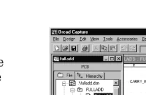
The Capture session frame
Once you start Capture, you see the Capture session frame. You do all your schematic design and processing within this window.
Figure 1 Capture’s session frame
The minimized Session Log icon in the lower left portion of the Capture session frame is the session log. The session log provides information about everything you have done in the current Capture session. Detailed information about this window—and the other windows in Capture—is given in Chapter 2, The Capture work environment.
In Capture, each design that you open is in a separate project manager window. If you need to work
simultaneously with several designs, you can open them all, and each will have its own project manager window.
The Capture work
environment
2
The project manager
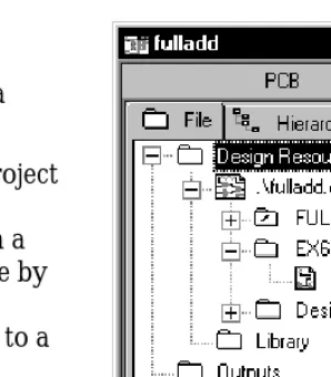
You use the project manager to collect and organize all the resources you need for your project. These resources include schematic folders, schematic pages, part libraries, parts, VHDL files, and output reports such as bills of materials and netlists. Figure 2 shows a new project manager window.
A project doesn’t actually contain all the resources. It merely “points to” the various files that the project uses. For this reason, be sure you don’t move or delete any files referenced by a project. If you do, the project won’t be able to find them.
The project file is saved with an .OPJ file extension. It is an ASCII file, and can be viewed in any text editor.
Project manager folders
The project manager provides a graphical display of a
project’s resources by grouping them into appropriate
folders, as described below.
• Shown underneath the Design Resources folder is the design folder with the design’s schematic folders and schematic pages, and a Design Cache folder that shows all the parts used on the schematic pages. Capture automatically adds any schematic folders or schematic pages that you create to the design folder. (In Figure 2, the design folder is named
DESIGN3.DSN.) You can add other files or
[image:28.612.38.181.63.222.2]information using the Project command on the Edit menu. For example, you can add an existing VHDL file to the design folder and later attach the models
Figure 2 New project manager window
The project manager
• The Library folder (in the Design Resources folder) shows the schematic part library files you’ve added to the project using the Project command on the Edit menu.
• The Outputs folder shows the output of Capture’s processing tools. Generally, these files include bill of materials reports and technology-specific netlists. Capture adds files to this folder when each is created.
Each project may have only one design, but may have multiple libraries. The design may consist of any number of schematics or VHDL models, but it must have a single
root module. The root module is defined as the top level of
the design. That is, all other modules in the design are referenced within the root module.
Within the project manager, you can expand or collapse the structure you see by double-clicking on a folder, or by clicking on the plus sign or minus sign to the left of a folder. A plus sign indicates that the folder has contents that are not currently visible; a minus sign indicates that the folder is open and its contents are visible, listed below the folder. It appears as a schematic folder with a slash on it in a design file, or as a page in a VHDL file.
Each project you open has its own project manager window. You can move or copy folders or files between projects by dragging them from one project manager window to another (as well as to and from Windows Explorer). To copy rather than move items, press and hold the
C
key while you drag them. If you close a project manager window, you close the project.In the project manager’s File tab, double-clicking on a schematic folder expands it and displays icons for each schematic page within the schematic folder. Then, if you double-click on a schematic page icon, the schematic page opens in a schematic page editor. Or, if the page is already open, its window becomes active.
Tip The root module for a design has a backslash in its folder icon, as shown in Figure 2 on page 2-6.
A design can consist of a single schematic page within a single schematic folder, or a number of schematic pages within a number of schematic folders. A schematic folder contains schematic pages in a relationship similar to that of a directory and the files it contains. Files are contained in a directory; schematic pages are contained in a
schematic folder.
A schematic page provides a graphical description of the electrical connectivity of a design. It is made up of parts, wires, and other electrical symbols. A schematic page may also contain borders, title blocks, text, and graphics. Capture acts on any schematic folders or schematic pages you have selected within an active project manager window. For example, the Find and Browse commands on the project manager’s Edit menu, the Print command on the project manager’s File menu, and the various tools on the Tools menu only apply to the selected schematic folder or page.
Note The project manager is also used to manage libraries and the parts they contain. This is covered in detail in
The project manager
Project manager tabs—File and Hierarchy
The project manager provides two ways to display a project’s resources.
If you choose the File tab (shown in Figure 3), the project manager displays all the project’s folders, schematic folders, and schematic pages. These are displayed in a tree-like fashion. You can expand or collapse the tree by clicking the plus sign in front of the icon. When that branch of the tree is expanded, the plus sign change to a minus sign.
If you choose the Hierarchy tab (shown in Figure 4), the project manager displays the hierarchical relationship among the project’s schematic folders and schematic pages.
For information about simple and complex hierarchical designs, see Chapter 6, Design structure.
Single view
In Capture v7.2 and earlier versions, Capture uses logical view and physical view to separate instance and
occurrence information. In Capture Release 9 and later, both instances and occurrences are together in a single view. The project manager shows all occurrences in the Hierarchy tab.
Capture v7.2 and earlier require you to change view before creating a netlist for use with Orcad Layout. In Capture Release 9 and later, the netlist tool provides an option to use either the instance properties or the occurrence properties for creating a netlist.
[image:31.612.358.507.63.233.2]Figure 3 File tab
Flat and hierarchical designs
In Capture, you can organize your schematics into flat or heretical structures and interface to downstream EDA products using either flat (popular for PCB layout) or hierarchical (popular for synthesis and simulation) netlists. The schematic system also supports reuse of schematics within a hierarchy so you only need to draw a schematic once, then instance it in multiple places for a variety of applications. This guide uses the following nomenclature to describe the parts and part properties of these reused schematics:
Simple hierarchy. A hierarchical schematic design with no reuse.
Complex hierarchy. A hierarchical schematic design with reuse.
Part instance properties. The properties of any part that has been placed in a schematic.
Part occurrence properties. The properties of a part that make it unique from others in reused schematics. Required to create a flat netlist with Capture.
Project manager pop-up menus
Several pop-up menus are available in the project
The schematic page editor
The schematic page editor
In the schematic page editor, you can display and edit schematic pages. You can place parts, wires, buses, and draw graphics. The schematic page editor has a tool palette that you can use to draw and place everything you need to create a schematic page. You can print from within the schematic page editor, or from the project manager window.
The part editor
Create and edit parts using the part editor.
Figure 6 Part editor
From the View menu of the part editor, you can choose Part or Package. In Part view you can:
• Create and edit parts and symbols, then store them in new or existing libraries.
• Create and edit power and ground symbols, off-page connector symbols, and title blocks.
• Use the tool palette’s electrical tools to place pins on parts, and its drawing tools to draw parts and symbols.
Package view shows the entire package. A package is a physical part that contains more than one logical part. You can edit the properties of the entire package, such as part reference, prefix, part alias, and so on. You cannot edit individual parts in this view, but you can select individual parts to edit by double-clicking on them.
The part editor is very similar to the symbol editor. The main difference between the two is the symbol editor’s lack of Pin and Pin Array tool palette buttons.
For more information, see The part editor tool palette on page 2-22.
See Chapter 11, About libraries
and parts for complete definitions of parts and packages. See Chapter 12,
The programmer’s editor
The programmer’s editor
Use the programmer’s editor to create or view VHDL files or other text files within Capture. VHDL keywords and comments are displayed in the colors you specify. (From the Options menu, choose Preferences and select the Text Editor tab.)
Figure 7 Programmer’s editor
To create a new VHDL file in the programmer’s editor
1 From the File menu, point to New, then choose VHDL File. A blank VHDL file appears in the text editor.
To open a VHDL file in the programmer’s editor
1 From the File menu, point to Open, then choose VHDL File. The Open VHDL File dialog box appears.
2 Select a file, then click OK.
Or
1 In the project manager, select a VHDL file.
2 Click the right mouse button, and choose Edit from the pop-up menu.
The session log
The session log lists the events that have occurred during the current Capture session, including messages resulting from using Capture’s tools. To display context-sensitive help for an error message, put the cursor in the error message line in the session log and press
1
.The ruler along the top appears in either inches or millimeters, depending on which measurement system (U.S. or Metric) you have selected in the Windows Control Panel. You can add tab settings to the ruler by clicking in the ruler bar and dragging the tabs to different positions, or remove them by dragging them down into the session log window. Capture saves your tab settings so that they reappear each time you start Capture.
Figure 8 Session log
You can search for information in the session log using the Find command on the Edit menu. You can also save the contents of the session log to a file, which is useful when working with Orcad’s customer support staff to solve technical problems. The default filename is SESSION.TXT.
The session log
To display the session log
1 Click on the session log’s maximize button, or choose Session Log from the Window menu.
To minimize the session log
1 Click the minimize button on the title bar.
To copy session log text to the Clipboard
1 Select the session log window to make it active.
2 Select the text and choose Copy from the Edit menu.
To print the session log
1 Select the session log window to make it active.
2 From the File menu, choose the Print command.
To use Find in the session log
1 Select the session log window to make it active.
2 From the Edit menu, choose the Find command. The Find dialog box appears.
3 Enter the word or words that you want to find.
4 Click Find Next.
To save the session log to a text file
1 Select the session log window to make it active.
2 From the File menu, choose the Save As command. The Save As dialog box appears.
3 Enter a file name in the File name text box. By default, the session log is saved to SESSION.TXT in the current directory. If necessary, specify a new location for the file.
The toolbar
Capture’s toolbar is dockable (that is, you can select an area between buttons and drag the toolbar to a new location) and resizable. By choosing a tool button, you can quickly perform a task. If a tool button is dimmed, you can’t perform that task in the current situation.
Figure 9 Capture’s toolbar
Some of the tools operate only on what you have selected, while others give you a choice of either operating on what is selected or expanding the scope to the entire project. Table 1 summarizes the tools on the toolbar. The tasks that these tools perform are described throughout this manual.
Table 1 Tools on the Capture toolbar
Tool Name Description
New Create a new document based on the active document. Similar to the New command on the File menu. For more information, see Creating new projects, designs, libraries, and VHDL files on page 3-52.
Open Open an existing project or library. Similar to the Open command on the File menu. For more information, see Opening existing projects, designs, libraries, and VHDL files on page 3-55.
Save Save the active document, schematic, or part. Equivalent to the Save command on the File menu. For more information, see Saving projects, designs, and libraries on page 3-58.
Print Print the selected pages in the schematic folder, or the active schematic page or part. Equivalent to the Print command on the File menu. For more information, see Chapter 5, Printing and plotting.
Cut Remove the selected object and place it on the Clipboard. Equivalent to Note The toolbar is always docked on the
The toolbar
Paste Paste the contents of the Clipboard at the cursor. Equivalent to the Paste command on the Edit menu.
Undo Undo the last command performed, if possible. Equivalent to the Undo command on the Edit menu.
Redo Redo the last command performed, if possible. Equivalent to the Redo command on the Edit menu.
MRU Place a part or symbol from the list of most recently used parts and symbols. For more information, see To place a part using the Most Recently Used (MRU) List on page 7-120.
Zoom In Zoom in to see a closer, enlarged view. Equivalent to choosing Zoom and In from the View menu. For more information, see To zoom in on page 10-188.
Zoom Out Zoom out to see more of your document. Equivalent to choosing Zoom and Out from the View menu. For more information, see To zoom out on page 10-188.
Zoom Area Specify an area of the schematic page or part to enlarge to fill the entire window. Equivalent to choosing Zoom and Area from the View menu. For more information, see To view a selected area on page 10-189.
Zoom All View the entire document. Equivalent to choosing Zoom and All from the View menu. For more information, see To view the entire page or part on page 10-191.
Annotate Assign part references to parts on the selected schematic pages. Equivalent to the Annotate command on the Tools menu. For more information, see Annotating on page 14-247.
Back Annotate Back annotate the selected schematic pages. Equivalent to the Back Annotate command on the Tools menu. For more information, see
Back annotating on page 14-266.
Design Rules Check
Check for design rules violations on the selected schematic pages. Equivalent to the Design Rules Check command on the Tools menu. For more information, see Checking for design rules violations on page 14-256.
Create Netlist Create a netlist for the selected schematic pages. Equivalent to the Create Netlist command on the Tools menu. For more information, see
[image:39.612.62.509.71.594.2]Displaying or hiding the toolbar
You can hide the toolbar, then display it again when you need it.
To display or hide the toolbar
1 From the schematic page editor’s View menu, choose Toolbar.
or
From the part editor’s View menu, choose Toolbar. Cross Reference Create a cross reference report for the selected schematic pages.
Equivalent to the Cross Reference command on the Tools menu. For more information, see Creating a cross reference report on
page 16-280.
Bill of Materials Create a bill of materials report for the selected schematic pages. Equivalent to the Bill of Materials command on the Tools menu. For more information, see Creating a bill of materials on page 16-275.
Snap-to-Grid Toggle schematic page and part editing to either on or off grid.
Project Manager Display the project manager window for the active document, providing an overview of project contents. Equivalent to choosing a project manager window by number from the Window menu.
Help Topics Open online help. Equivalent to the Help Topics command on the Help menu.
The tool palettes
The tool palettes
Capture has two tool palettes: one for the schematic page editor and one for the part editor. Both tool palettes are
dockable (that is, you can click on an area between buttons
and drag a tool palette to a new location) and resizable. While the drawing tools on the two tool palettes are identical, each tool palette has different electrical tools. After you choose a tool (and, in the case of some tools, after you respond to the tool’s dialog box), click the right mouse button to display a context-sensitive pop-up menu.
The schematic page editor tool palette
The first group of tools on the tool palette is electrical tools, used to place electrical connectivity objects. The second group is drawing tools, used to create graphical objects without electrical connectivity.
Figure 10 Schematic page editor tool palette
Table 2 describes the tools on the schematic page editor tool palette.
Note The tool palette is always docked on the right edge of the session frame the first time you open a schematic page or part in a new session of Capture. The position of the tool palette is not saved.
For information on using the electrical tools, see Chapter 7, Placing,
editing, and connecting parts and symbols. For information on how to use the drawing tools, see Chapter 8,
Table 2 Tools on the schematic page editor tool palette
Tool Name Description
Select Select objects. This is the normal mode.
Part Select parts from a library for placement. Equivalent to the Part command on the Place menu. For more information, see Placing parts on page 7-118.
Wire Draw wires. Press and hold
S
to draw non-orthogonal (not a multiple of 90°) wires. Equivalent to the Wire command on the Place menu. For more information, see Placing wires on page 7-149.Net Alias Place aliases on wires and buses. Equivalent to the Net Alias command on the Place menu. For more information, see Placing buses on page 7-152.
Bus Draw buses. Press
S
to drawnon-orthogonal segments. Equivalent to the Bus command on the Place menu. For more
information, see Placing buses on page 7-152.
Junction Place junctions. Equivalent to the Junction command on the Place menu.
Bus Entry Draw bus entries. Equivalent to the Bus Entry command on the Place menu. For more information, see Placing bus entries on page 7-153.
Power Place power symbols. Equivalent to the Power command on the Place menu. For more information, see Placing power and ground symbols on page 7-128.
The tool palettes
Hierarchical Block
Place hierarchical blocks. Equivalent to the Hierarchical Block command on the Place menu. For more information, see Placing hierarchical blocks on page 7-134.
Hierarchical Port
Place hierarchical ports on schematic pages. Equivalent to the Hierarchical Port command on the Place menu. For more information, see Placing hierarchical ports on page 7-139.
Hierarchical Pin
Place hierarchical pins in hierarchical blocks. Equivalent to the Hierarchical Pin command on the Place menu. For more information, see Placing hierarchical pins on page 7-141.
Off-Page Connector
Place off-page connectors. Equivalent to the Off-Page Connector command on the Place menu. For more information, see Placing off-page connectors on page 7-144.
No Connect Place no-connect symbols on pins. Equivalent to the No Connect command on the Place menu. See
Placing and editing no-connect symbols on page 7-132.
Line Draw lines. Equivalent to the Line command on the Place menu. For more information, see
Drawing lines on page 8-159.
Polyline Draw polylines. Press and hold
S
to draw non-orthogonal polylines. Equivalent to the Polyline command on the Place menu. For more information, see Drawing polylines and polygons on page 8-163.Rectangle Draw rectangles. Holding
S
constrains to a square. Equivalent to the Rectangle command on the Place menu. For more information, seeDrawing rectangles and squares on page 8-160.
Ellipse Draw ellipses. Holding
S
constrains shape to a circle. Equivalent to the Ellipse command on the Place menu. For more information, seeThe part editor tool palette
The first group of tools on the part editor tool palette are electrical tools, used to place pins and IEEE symbols. The second group of tools are drawing tools, used to create graphical objects without electrical connectivity.
Figure 11 Part editor tool palette
Table 3 describes the tools unique to the part editor tool palette. The drawing tools are described in the previous section, The schematic page editor tool palette on page 2-19. Arc Draw arcs. Equivalent to the Arc command on the Place menu. For more information, see Drawing arcs on page 8-162.
Text Place text. Equivalent to the Text command on the Place menu. For more information, see Placing text on page 8-168.
Table 3 Tools on the part editor tool palette
Tool Name Description
IEEE Symbol
Place IEEE symbols on a part. Equivalent to the IEEE Symbol command on the Place menu. For more information, see Adding graphics, text, and IEEE symbols to a part on page 12-217.
Table 2 Tools on the schematic page editor tool palette (continued)
For information on how to use the electrical tools, see Chapter 12, Creating
and editing parts. For information on how to use the drawing tools, see
The tool palettes
Pin Place pins on a part. Equivalent to the Pin command on the Place menu. For more information, see Placing pins on a part on page 12-218.
Pin Array Place multiple pins on a part. Equivalent to the Pin Array command on the Place menu. For more information, see Placing pins on a part on
page 12-218.
Displaying or hiding a tool palette
Like the toolbar, you can hide a tool palette, then display it again when you need it.
To display or hide a tool palette
1 From the schematic page editor’s View menu, choose Tool Palette.
or
The status bar
The status bar
The status bar, located at the bottom of the Capture session frame, reports on current actions, number of items selected, zoom scale, and pointer location.
Figure 12 The status bar
Left field
The left field displays descriptions of selected tools or menu items, prompts, or the current status.
Center field
The center field displays the number of items selected in the schematic page editor or part editor.
Right field
The right field displays the current scale and pointer location (such as: Scale=50% X=10.0 Y=5.0). The location in the schematic page editor is measured in either inches or millimeters, depending on the Units settings in the Schematic Page Properties dialog box (Page Size tab). The pointer location in the part editor is measured in grid units.
Displaying or hiding the status bar
You can hide the status bar, then display it again when you need it.
To display or hide the status bar
1 From the schematic page editor’s View menu, choose Status Bar.
or
Selecting and deselecting objects
Selecting and deselecting objects
Once you select an object, you can perform operations on it, including moving, copying, cutting, mirroring,
rotating, resizing, or editing. You can also select multiple objects and edit them, or group them into a single object. Grouping objects maintains the relationship among them while you move them to another location.
This section describes different ways to select individual objects and groups of objects in both the schematic page editor and the part editor.
To select an object
1 Position the pointer on the object and click the left mouse button. The object displays in the selection color.
To reset the selection color
1 From the Options menu, choose Preferences, then select the Colors tab.
2 Click the left mouse button on the Selection color.
3 Click to select a color from the Selection Color
window, then click OK. Click OK again to dismiss the Preferences dialog box.
To select multiple objects
1 For each object to select, position the pointer on the object and hold
C
while you click the left mouse button. Every object in the selection set displays in the selection color.To deselect objects
1 Click on the schematic page away from any objects. Selected objects become deselected. Keep in mind that a part occupies a rectangular area encompassing all its graphics. This means that a part may occupy a larger area than is initially apparent.
Note You can edit the properties of a group of objects using the property editor. See The property editor on page 34.
To select all objects in an area
1 From the tool palette, choose the selection tool.
2 Click on an area away from any objects or parts to deselect any items that may be selected.
3 Move the pointer to one corner of the area to select. Press and hold the left mouse button while you drag the mouse to the opposite corner, then release the left mouse button. Every object in the selection set appears in the selection color.
To include or exclude objects intersected by your selection
rectangle
1 From the Options menu, choose Preferences.
2 On the Select tab, select one of the Area Select options. You can choose Intersecting to include items that are not fully enclosed by your selection rectangle, or choose Fully enclosed to exclude items that were not entirely selected.
To select all objects on a schematic page or part
1 From the Edit menu, choose Select All. All objects appear in the selection color.
To select an object from a set of objects stacked atop one another
1 Position the pointer over the stack of objects.2 Press
F
while you click the left mouse button. This cycles through the objects in the stack.To remove one object from a selection set
1 Place the pointer over the object, press
C
, and click the left mouse button.Selecting and deselecting objects
Grouping objects
Use the Group command on the Edit menu to group multiple objects into one selectable object. This is a convenient way to maintain the relationship among several objects while moving them to another location. You can nest groups, meaning a group can contain other groups as well as objects.
The Group command is only available when multiple objects are selected. Objects remain grouped until you ungroup them or close the schematic page or part that contains them.
To group multiple selected objects
1 Select the objects you want to group. (See Selecting and deselecting objects on page 2-26 for more information).
2 From the Edit menu, choose Group. You can move the objects as a group.
3 When have finished working with the objects as a group, you can ungroup them. From the Edit menu, choose Ungroup.
Caution The Group command will not be available if your selection includes a net alias (a property). After block selecting the objects you want to group, deselect the included net aliases by holding the
C
Editing properties
In a Capture schematic design, each object has properties that define their characteristics. These objects include:
• Parts (including hierarchical blocks)
• Nets (including constituent nets within buses)
• Pins
• Globals
• Aliases
• Hierarchical ports
• Off-page connectors
• DRC markers
• Bookmarks
• Title block
A property consists of a property name (for example, Part Value or Part Reference) and an associated value (for example, TIP31C or Q2). For example, part properties define the name, value, reference designator, and other information for each part in your design.
In Capture you can edit property values, create or delete properties, or cause the properties to be displayed on the schematic page.
Use one of three editors to edit properties:
• The Browse spreadsheet editor, as described on page2-31.
• The property editor, as described on page2-34.
Editing properties
Instance and occurrence properties
Since Capture allows for complex hierarchical design structures (as discussed in Chapter 6, Design structure), each of the objects listed above can exist as instances or
occurrences.
In complex hierarchical designs, a schematic page can be referenced (or reused) at several points in the design. An
instance refers to the object that is placed on the defining
schematic. An occurrence represents the use or reuse of that instance within a design. When you edit properties for an object, you can edit the instance, or you can edit a particular occurrence of that instance.
Instance properties
An instance property is a user property applied to the placed instance of a part or symbol in the design. This includes PCB Footprint, Value, and Name properties of each placed part or symbol in a design. The instance property overrides the library definition.
An instance property will “shine through” to all occurrences of that instance unless it is overridden by occurrence properties. A change using any of the tools, like Annotate, also may update the instance property.
Occurrence properties
An occurrence property is a user property applied to multiple occurrences of place instances of parts or symbols in a design. The occurrence property overrides the instance property definition.
The spreadsheet editors expand to display occurrence properties if values are different from the instance value. To quickly hide or display all the occurrence properties, press and hold the
C
key while clicking on one of the plus (+) symbols in the property editor.The Browse spreadsheet editor
You display the Browse spreadsheet editor from the project manager’s Edit menu, the schematic page editor, or the part editor. The particular Browse spreadsheet that you display depends on the object you select from the Browse pull-right menu. The options include:
• Hierarchical ports
• Off-page connectors
• DRC markers
• Bookmarks
• Part (including hierarchical block) occurrences
• Net (including constituent nets within a bus)
occurrences
• Pin properties
• Title block occurrences
• Flat nets
The Browse spreadsheet editor browses the entire design for the objects you select, then displays their properties. Each property appears as a column heading in the spreadsheet. Each row is an object located by the editor.
It is important to note that, in the Browse spreadsheet editor you can only edit properties for occurrences. The only exception being in the part editor, where you can only edit instances. To edit instance properties, you must use the property editor discussed in The property editor on page 2-34.
Editing properties
To create a new property in the Browse spreadsheet editor
1 In the first column of the Browse spreadsheet, selectthe object or occurrence for which you want to create the new property.
2 From the Edit menu, choose Properties. Capture displays the object in a new Browse spreadsheet window.
3 Click New. Capture displays the New Property dialog box.
4 Enter a name and value for the new property, then click OK. Capture adds the property to the object or occurrence and displays the new property in the original Browse spreadsheet.
To copy a value from one property to another property in the
Browse spreadsheet editor
1 In the first column of the Browse spreadsheet, select the object or occurrence that has the property with the value you want to copy.
2 From the Edit menu, choose Properties. Capture displays the object in a new Browse spreadsheet window.
3 Select the cell that contains the value you want to copy.
4 Click Copy.
5 Select the cell that you want to contain the copied value.
To remove a user-defined property in the Browse spreadsheet
editor
1 In the first column of the Browse spreadsheet, select the object or occurrence that has the property you want to remove.
2 Select the column heading for the property you want to remove.
3 Click Remove. Capture removes that property from the object.
To replace property values
1 Select the objects whose properties you want to edit. Note that the objects must be of the same type (for example, all pins or all hierarchical ports); otherwise, the Properties command is grayed out.
2 From the Edit menu, choose Properties. The Browse spreadsheet appears.
3 Double-click on a cell holding the value you wish to replace, then enter the new value.
4 Click the copy button.
5 Select the cells that are to receive the replacement value.
6 Click the Paste button. The replacement value appears in the selected cells.
7 Click the OK button to close the Browse spreadsheet.
Note Some properties cannot be removed as they are essential for creating a netlist. You can only remove user-defined properties.
Note If you remove a property from an occurrence for which there is a defined instance property, the occurrence property is not removed, but rather, the instance property value “shines through” to the occurrence. In order to remove an instance property you must use the property editor.
Editing properties
The property editor
You display the property editor either by selecting items on a schematic page, then choosing Properties on the Edit or popup menu, or by simply double-clicking on an item in the schematic page editor.
The property editor allows you to edit properties for instances or occurrences of the following objects:
• Parts (including hierarchical blocks)
• Nets (including constituent nets within buses)
• Pins
• Title blocks
• Globals
• Ports
• Aliases
The property editor is constrained such that it can only edit instances or occurrences on the active schematic page. To browse and edit properties for an entire design, see The Browse spreadsheet editor on page 2-31.
The property editor window
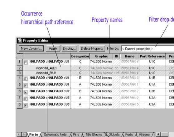
[image:58.612.200.479.171.391.2]The properties that appear in the property editor depend on the items selected in the schematic page. Also, these properties depend on the tab selection at the bottom of the property editor. For example, if the Parts tab is active, the properties for selected parts appear in the property editor.
Figure 14 Property editor
Each column in the property editor is a placeholder that you can use to add properties.
Each row is an instance or occurrence. Occurrence rows appear in yellow below their associated instance row. They only appear if one or more occurrence property values are different from the instance property values and you expand the instance by clicking the plus sign (+) to the left of the instance name.
Note When you first start the property editor all instance properties are displayed. Occurrence properties are displayed only if they have their own values assigned to them (independent of the instance property values).
Instance name
Property names Filter drop-down list
Item selection tabs Occurrence
Property value schematic name:page:reference
Editing properties
cross-hatch pattern, the corresponding property does not have an occurrence value, causing the instance property value to “shine through” to the occurrence.
New Column or New Row
Displays the Add New Column dialog box or the Add New Row dialog box, depending on the property editor orientation. These dialog boxes add a new property column or row, respectively. To add the property to an object, you must enter a property value for the object.Apply
Applies the changes in the property editor to the schematic page. The Apply button does not dismiss the property editor. You can also apply the changes to the schematic page by closing the property editor.Display
Opens the Display Properties dialog box to set the display options of the selected property and its value. You cannot display properties of an occurrence property using the Display Properties dialog box.Delete Property
Deletes the property, if editable, from the selected object or objects. If you select all of aproperty’s cells and click the Delete Property button, the property will be removed from the selected objects but will remain in the filter. This is indicated by the
cross-hatch pattern that appears in the cell.
Filter by
Specifies a filter by which you can view objects. Use the filters available in the drop-down list to constrain the available properties. Each filter is a set of properties that are typically useful for particular project types. For example, the Actel Designer Part/NetProperties filter includes properties that are useful for constraining a PLD project for integration with Actel’s Designer software. The Capture filter displays common schematic capture properties available to most parts. The Layout filter displays properties needed to send a design
Note You can pivot the property editor spreadsheet. Instances and occurrences appear in columns across the top and properties appear in rows. This may be advantageous if your selected object or objects have several properties. See To pivot the property editor spreadsheet on page 2-38.
the property editor to display all properties that currently exist for the selected item. For more information, see The property editor Filter menu on page 2-39.
Parts tab
Displays the parts of the selected objects, including hierarchical blocks.The Graphic property column provides the option to toggle the display of the part between Normal and Convert view. When you click the Graphic cell, a down arrow indicates a drop-down list where you can select a different view.
Schematic Nets tab
Displays the schematic nets of the selected objects, including constituent nets within buses.Pins tab
Displays the pins of the selected objects, including hierarchical pins in hierarchical blocks.Title Blocks tab
Displays the title blocks of the selected objects. With this tab, you can add a property to the Title Block instance on a schematic page that displays the full hierarchical path to the schematic.Globals tab
Displays selected globals for simultaneous editing of multiple names.Ports tab
Displays the source symbol, source library, and type of port. This tab provides for simultaneous editing of multiple ports.Editing properties
To pivot the property editor spreadsheet
1 Right-click the empty cell in the top-leftmost position of the spreadsheet.
2 From the pop-up menu, choose Pivot.
To display or hide all occurrence properties
1 To display all occurrence properties, press and hold the
C
key while clicking on one of the plus (+) symbols in the left-most column.2 To hide all occurrence properties, press and hold the
C
key while clicking on one of the minus (-) symbols in the left-most column.To move columns in the property editor
1 Select the column you want to move by clicking on its title cell.
2 Drag the column to the new location.
To sort columns in the property editor
1 Right-click on the column heading. A pop-up menu appears.
2 Choose Sort Ascending or Sort Descending.
Note The Find command searches down columns in the spreadsheet, regardless of the spreadsheet orientation.
The property editor Filter menu
The property editor filter is a powerful tool with which you can show or hide properties on selected objects. You can use the pop-up Filters menu on the spreadsheet to view the status of a property or edit columns, tabs, or the entire property editor spreadsheet.
You can add, delete, or change any filter except the <Current properties> filter. The <Current properties> filter displays all properties as undefined until you create or select another filter.
When you create a new filter, all properties appear undefined, just as in the <Current properties> filter. If you right-click a column heading and select Filters from the pop-up menu, you will see that each property is
Undefined, and the filter specifies Show Undefined. Your results will be more reliable if you use the property editor Filters menu to make changes rather than editing the PREFPROP.TXT file manually.
Changes to the filters are saved to PREFPROP.TXT when you close the spreadsheet. If you need to retrieve the original version, you can copy PREFPROP.TXT from the Orcad installation CD in the Capture directory.
The first four choices on the Filter menu apply to the appearance of a particular tab and column.
Show
The selected column always appears when you use the filter, unless the filter is inverted.Editing properties
Undefined
The selected property is not defined. It isn’t included or excluded from the filter.You can control the display of undefined properties on individual tabs with the next two choices on the Filter menu. Select any combination of the two.
Show Undefined
Specifies that any undefinedproperty columns that are selected appear when you use the filter. However, if you also select Invert Filter, these same selections will not appear.
Defined properties appear at the beginning of the spreadsheet (toward the left side) when you select this option.