TECHNICAL NOTE
In Vitro Studies of the Neuroform Microstent
Using Transparent Human Intracranial Arteries
S.-W. Hsu J.C. Chaloupka J.A. Feekes M.D. Cassell Y.-F. Cheng
For better understanding of relevant morphology and mechanics, direct visualization of a Neuroform microstent (NFM) within an actual human intracranial artery is essential. Twelve NFM were deployed into 8 various segments of formaldehyde-fixed cadaver intracranial arteries. The arteries were then dehydrated and cleared in methyl salicylate to create transparency. The morphology of NFM was studied by digital macro-photography with a back illumination system. The possible limitations and important findings of the NFM were discussed.
T
he Neuroform microstent (NFM; Boston Scientific/Tar-get, Fremont, Calif) is the first microcatheter-delivered stent used for treatment of intracranial wide-neck aneu-rysms.1Despite our substantial clinical experiences with the NFM since its availability, a variety of technical difficulties have been encountered that are difficult to resolve, at least in part because of the poor visibility of most of the NFM under fluoroscope and angiography. The purpose of this study is to better assess relevant morphology and mechanics of the NFM stent by direct visualization within actual human intracranial arteries, by using a novel adaptation of a method for creating transparent vessels.2Description of Technique
Intracranial arteries were harvested by dissection from form-aldehyde-fixed cadaver brains and skull bases available from donors to the Deeded Body Program at The University of Iowa, College of Medicine. Multiple arterial segments, includ-ing the cavernous portion of the internal carotid artery (ICA), the distal-ICA-to-middle-cerebral-artery (MCA) segment, the distal-ICA-to-anterior-cerebral-artery (ACA) segment, the vertebrobasilar artery (VBA), the basilar artery (BA), and the BA-to-posterior-cerebral-artery (PCA) segment were ob-tained. The vessels were then cleaned by removal of blood clots and any attached arachnoid tissue, followed by storage in a 1% formaldehyde solution.
Understanding the structure of the NFM is essential for assessment of its use (Fig 1). The NFM is made of a nickel-titanium alloy known as nitinol, which possesses a high degree of elasticity and deformability because of its self-expandable properties. Most the stent is radiolucent except the bilateral platinum end markers. The stent is constructed by segmental connections of a variable number of sinusoidal crown seg-ments, the so-called open cell design. Each crown segment length is approximately 2.5 mm. Therefore, a 20-mm length
NFM has 8 crown segments. Adjoining crown segments have 2 connection points (struts) that are approximately 180° in ori-entation and approximately 90° difference between adjacent struts. Neuroform2 microstent (NF2) is the second generation of NFM with a minor modification of the end platinum mark-ers and improvement of the microdelivery system. The struc-ture of the stent body and the characteristics of NF2 are the same as NFM.
Using the push-pull technique similar to clinical applica-tion, NFM (including NF2) were deployed into specific loca-tions of arteries immersed in a Petri dish filled with warm saline. The temperature was maintained at 38°C for obtaining maximum expansion of the NFM. There were 2 purposes for the selected locations of NFM deployment; first, the location of common aneurysms seen clinically, and second, those loca-tions that would mimic the neck of an aneurysm. The junction at larger caliber side branches, such as the conjoining point of a vertebrobasilar artery or a major arterial bifurcation, could be considered the neck of an aneurysm. Stent deployment across major side branches of a parental artery was used to simulate an artery with an aneurysm. To simulate the loca-tions of NFM deployment commonly seen in the clinical set-ting as well as the mimicked neck of an aneurysm, the intra-petrous portion of the ICA, the cavernous portion of the ICA, the distal ICA to MCA, the ACA from A1 to A2, and the distal BA to PCA were selected as NFM deployment locations. Stent diameter was selected to be either nearly exact or oversized. No actual intracranial arterial aneurysms were available for our study.
Arteries with NFM in position underwent a standard dehy-dration process beginning with 70% alcohol solution and fol-lowed by 95% and 100% alcohol solutions at room tempera-ture. The artery was kept in each solution for at least 24 hours. The dehydrated arteries were then immersed in 100% methyl salicylate (Fisher Scientific, Fair Lawn, NJ) and became trans-parent within 20 minutes (Fig 2). The transtrans-parent arteries with Received August 30, 2005; accepted after revision December 21.
From the Section of Neurointervention (S.-W.H., J.C.C.), Department of Radiology, The University of Iowa Hospitals and Clinics, Iowa City, Iowa; Department of Anatomy and Cell Biology (J.A.F., M.D.C.), College of Medicine, The University of Iowa, Iowa City, Iowa; and Graduate Institute of Clinical Medical Sciences (S.-W.H., Y.-F.C.), Chang Gung University, Kaohsiung Divison, Taiwan, Republic of China.
This work was supported in part by grant number CMRPG840341 from Chang Gung Medical Research Project, Chang Gung Memorial Hospital, Taiwan.
This article was presented previously as a scientific poster at the 42nd Annual Meeting of the American Society of Neuroradiology; 2004 June 5–11; Seattle, Wash.
Address correspondence to Shih-Wei Hsu, MD, Division of Neuroradiology, Department of Diagnostic Radiology, Chang Gung Memorial Hospital Kaohsiung Medical Center, 123 Ta-Pei Rd, Naio-Sung County, Kaohsiung, Taiwan 833, Republic of China.
Fig 1.Macro-digital photography of an expanded 3.5⫻20 mm Neuroform2 microstent. Only the platinum markers at the bilateral ends are radiopaque (arrowheads). The struts (arrows; do not indicate all struts) are connecting the crown segments. Each segment has 2 struts with approximately 180° in orientation and 90° difference in between adjacent struts.
INTERVENTIONAL
TECHNICAL
[image:1.585.303.534.182.253.2]NFM in place were kept in a Petri dish filled with methyl sa-licylate and put on a homogenous ground-glass, back-illumi-nation system at room temperature. Macro-digital photogra-phy was taken from multiple angles to view the intravascular NFM morphology. The relationship between the stent and vascular wall as well as the stent and the mimicked aneurysm neck (the side branch that the NFM crosses) were studied. Different locations of the stents with their characteristic mor-phologic changes in specific arterial locations were also investigated.
Twelve NFMs were deployed into 8 var-ious intracranial arterial segments (Figs 3– 8). Good conformity as well as a smooth profile was generally observed within most of the arterial segments. However, increasing vessel curvature caused focal intercrown separation (diminished scaffolding) along the greater curva-ture of an artery. Conversely, along the lesser curvacurva-ture of an arterial segment, there was a tendency for crowns to imbricate, though, overall, the conformity of the stent along minor cur-vatures remained good. Sinusoidal elements of a crown seg-ment of NFM may protrude into major side branches, and there is no connecting strut close to the interface of the parent artery and side branch (Fig 3).
Owing to the “open cell design,” markedly asymmetric en-largement of a cell or multiple cells can occur, particularly when the stent was deployed into the segments with angula-tion. This was commonly seen in stents deployed across the distal BA to the PCA continuum (Figs 4 and 5) or within the anterior genu of the carotid siphon as well as petrous or/and cavernous ICA (Fig 6). In addition to larger gaps along the greater curvature of an artery, the crown segments consis-tently did not attach well to the vessel wall along the lesser curvature of cavernous and petrous ICA. In segments where there was an abrupt change in diameter within the curvature (eg, BA-PCA continuum), the connecting struts could rotate to within less than the ideal 180° orientation, which resulted in
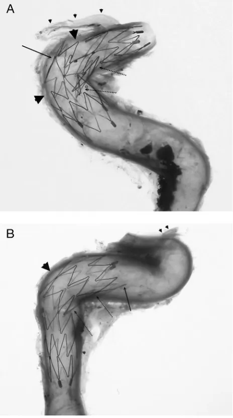
Fig 2.Comparison of a vertebrobasilar artery with its major branches and proximal posterior cerebral arteries before (A) and after (B) the artery was made transparent. Two Neuroform microstents are in position (arrow-heads). One stent is across the left vertebral and basilar artery and another is located across the distal basilar artery and posterior cerebral artery. The stents are clearly visualized through the artery after arteries are made transparent (B). Using this method, assessment of the mechanical behaviors of Neuroform microstent in actual human intracranial arteries is possible. Extensive atherosclerotic plaques (arrows) are noted in this spec-imen that involve the right vertebrobasilar junction, the distal basilar artery, and the bilateral posterior cerebral arteries.
[image:2.585.52.372.42.601.2]a large and asymmetric intersegmental gap at the opposite end of the stent (Fig 4). Good end-crown attachment to the vessel wall was not always achievable, especially when the stent met a curve (Fig 7). Atherosclerotic plaques were observed in several
specimens, which caused focal areas of poor stent attachment to the vessel wall.
We observed a connecting strut positioned at the origin of a major side branch and considered that this could happen at the neck of a true aneurysm (Fig 8). The continuity of the stent profile was smooth without protruding part of the crown into the side branch. The NFM is self-expandable and maintains a straight, tubular configuration once expanded. Although flex-ible and able to adjust to bends or curves present in the vascu-lature, the stent will automatically straighten out provided an opportunity, and so a small longitudinal pressure is exerted along the vessel wall at any points of contact that inhibit the stent from straightening out to its original configuration. This longitudinal rebounding force straightened a small arterial stump in one of the models (ACA complex, A1 to A2 in Fig 8). To minimize this, a thin sheath was fixed between the trunk of the BA and the PCA before stent deployment to maintain the original angulation (Fig 5).
Discussion
Wide-neck aneurysms have been a challenging scenario for endovascular treatment. Several techniques and endovascular devices have been developed for the treatment of wide-necked aneurysms, including balloon-assisted neck remodeling, 3D coils, and stent assisted coiling.3The NFM is the most recently developed endovascular microstent with self-expandable and micro-delivery properties that are specially designed for the treatment of intracranial wide-neck an-eurysms by using stent-assisted coiling. However, the NFM is radiolucent un-der fluoroscope except the bilateral platinum end markers. Simulations of arteries with transparent characteristics such as silicon models have been at-tempted. This model may provide sim-ilar vascular morphology, elasticity, and the anatomic location of aneu-rysms, but the biologic characteristics of the arterial wall are completely dif-ferent. The deployment and position-ing of the NFM in this model is not ad-equate to simulate actual human intracranial arteries. Glass tube models have perfect transparency but do not simulate the vascular morphology, an-atomic location, or vessel wall charac-teristics of actual intracranial arteries.4
Methods for producing transparent arteries were developed several decades ago.2This is the first study to use such methods for investigation of the NFM in human cadaver intracranial arteries. Some of the physical properties of “transparentized” arteries are different from in vivo human arteries, which may be a limitation of this study. First, the calibers of the arteries become smaller (approximately 10%–20%) be-cause of fixation and dehydration pro-cesses. Second, the arteries become
Fig 4.Magnified view of the upper stent (Neuroform2 microstent with the size of 3.5⫻
20 mm) shown in Fig 2. The stent placed in the basilar artery to left posterior cerebral artery (PCA) continuum with angulated configuration shows a significant gap in the stent just at the bifurcation of the right PCA (arrowhead), which barely covers the opening of the right PCA. The connecting struts rotated to within less than the ideal 180° orientation (arrow), resulting in a very large and asymmetric intersegmental gap at the opposite end (dot-line arrow) of the stent.
[image:3.585.91.247.42.205.2] [image:3.585.54.366.360.726.2]much less elastic and more rigid compared with the in vivo arteries, again because of the fixation and dehydration. An-other greater limitation is that the transparent arterial model cannot simulate the dynamic status of in vivo arteries because their physical properties changed. The simulation of pulsatile blood flow was not re-established in our transparent arteries when we deployed the NFM and observed the morphologic changes of the NFM. Despite this, however, their anatomic-geometric characteristics are largely well preserved compared with their original configuration. In addition, the NFM was deployed before the dehydration process, when the artery was much less rigid and possessed its nearly normal caliber. Thus, the current study of NFM is capable of providing important insights for the device’s postdeployment steady behavior in
actual human intracranial arteries, which cannot be achieved in the clinical setting.
The NFM is made of nitinol, a shape memory alloy. The austenite temperature of the NFM is body temperature, at which the stent will transform from martensite to austenite, the original cylindrical configuration of the stent. The deploy-ment of the NFM occurred at body temperature for obtaining maximum expansion of the stent. Once a stent was deployed,
Fig 6.Neuroform microstents (4.5⫻15 mm) placed in cavernous (A) and petrous (B) segments of the internal carotid artery crossing the angulations of the vessels. Significant large gaps are observed in the greater curvature of the vessels (arrowheads), except that one connecting strut is in place (arrowinA). If this connecting strut were located at the actual neck of an aneurysm, the stent would have a good bridge for coiling. On the other hand, the crown segments of the stent are consistently not well attached to the arterial wall along the lesser curvature of the vessels (dot-line arrows). The end of the stent is also not always attached well to the vessel wall especially at arterial curves (arrowinB). Ophthalmic arteries are indicated (small arrowheads).
Fig 7.A 3.5⫻20-mm Neuroform2 microstent deployed from the terminal end of the internal carotid artery to the middle cerebral artery. A small part of the crown segment protrudes into the M2 bifurcation (arrow). The end of the stent is not attached to the artery very well, particularly at arterial curves (arrowheads). This finding is relatively common in other specimens.
[image:4.585.301.535.41.180.2] [image:4.585.54.286.45.461.2] [image:4.585.300.535.242.526.2]the crown segments of the stent attached to the vessel wall would not easily move or change shape because the dehydra-tion and clearing as well as the observadehydra-tion process in our study is a steady state. The configuration and morphology of NFM in transparent arteries at room temperature were be-lieved to be nearly the same as those initially deployed at body temperature.
Although no actual aneurysms were present in the speci-mens used, NFM deployed across large-caliber side branches or bifurcation points can be viewed as an anatomic equivalent to an aneurysm neck. As such, this study clearly showed that stent elements can either protrude significantly into the aneu-rysm or can be poorly oriented to provide inadequate scaffold-ing. The ability of the NFM to properly bridge the neck of an aneurysm seems to be affected by at least a few factors, includ-ing the degree of curvature of the artery, stent sizinclud-ing, location of the connecting strut, and vessel diameter transitions. Poor scaffolding of the NFM was frequently observed within curved segments of the vessels, particularly along the region of greater curvature or at points of angulation. The connecting strut of the stent could randomly abut the origin of a side branch; although in most cases this would probably not have adverse consequences, very small branches could suffer direct or indi-rect flow obstruction or disturbances. Conversely, the strut may be positioned at the neck of an aneurysm and thereby provide an ideal scaffolding support for Guglielmi detachable coiling (Fig 8B).
A NFM deployed across an artery with angulation exerts a certain longitudinal rebounding force and could straighten the angle of the parent artery (Fig 8). This phenomenon could have adverse consequences, such as proximal or distal arterial kinking, dissection, asymmetric mechanical strain on the an-eurysm, or increased compliance mismatch at the stent ends, which might cause marginal or in-stent stenosis.5The manu-facturer recommended that the NFM needs 4 mm of length in both proximal and distal ends of the parental artery for secur-ing the stent in position. We believe that in arteries with an-gulations, the NFM may need more “secure length” on both ends because of the longitudinal rebounding force. Therefore, if the secure length is not long enough, the force may cause the distal end of the stent to dislodge and jump into the aneurysm. We have experienced one such case but fortunately the aneu-rysm was safely coiled after a second NFM was deployed by using a stent-through-stent method similar to that described by Broadbent et al.4
Although atherosclerosis and arterial aneurysm are 2 dif-ferent disease entities, the intracranial artery harbored with an aneurysm may rarely be associated with atherosclerosis of the parental artery. In atherosclerotic arteries, the lumen is nar-row and irregular, and we observed that the attachment of NFM end-markers to the vessel wall was not very good and that the NFM might experience less expansion. In addition, in
arteries with angulations, the NFM has larger gaps in its body than expected. This seems to be the case in Fig 3, of the BA-PCA continuum, which also reveals extensive atherosclerotic plaques. In this case, the gaps of the NFM are probably larger than what one would observe in cases involving nonathero-sclerotic associated aneurysms at this particular location.
The strut number for each segment of the NFM is an im-portant factor that may cause such larger gaps within the stent along arteries with angulations. As described previously, there are only 2 struts for connecting each segment of the NFM. To improve this adverse effect, the third generation Neuro-form3 (NF3; Boston Scientific/Target) was recently made available. The NF3 has 3 struts for connecting each segment over the middle crowns of the NFM. Ideally, increasing one strut will improve the stent profile and perhaps produce better scaffolding for containing coils in aneurysms that are located at curves or within angulated arteries.
Conclusions
Transparent human arteries are excellent models for evaluat-ing certain important physical properties and the morphology of radiolucent stents such as the NFM. Although this model is not a complete simulation of in vivo human arteries because of fixation and dehydration processes producing smaller, more rigid arteries, the ability to directly visualize the stent and its relationship with vascular walls provides very important in-formation that may not be obtainable in clinical settings. Our preliminary studies revealed several significant findings re-garding the NFM. Proper sizing seems to be important for ensuring good stent conformity within the arteries, particu-larly when significant curvature is encountered. NFM deploy-ment in arterial segdeploy-ments or branches with angulation could be problematic, potentially resulting in excessive gaps in be-tween stent crown segments that probably will not provide adequate scaffolding for containing coils within an aneurysm. The operators should be aware that longitudinal rebounding force exists when the NFM is deployed at curved or angulated positions. Different complications may arise from this longi-tudinal rebounding force.
References
1. Howington JU, Hanel RA, Harrigan MR, et al.The Neuroform stent, the first microcatheter-delivered stent for use in the intracranial circulation. Neuro-surgery2004;54:2–5
2. Karino T, Motomiya M.Flow visualization in isolated transparent natural blood vessels.Biorheology1983;20:119 –27
3. Lylyk P, Cohen JE, Ceratto R, et al.Endovascular reconstruction of intracra-nial arteries by stent placement and combined techniques.J Neurosurg2002; 97:1306 –13
4. Broadbent LP, Moran CJ, Cross DT, et al.Management of Neuroform stent dislodgement and misplacement.AJNR Am J Neuroradiol2003;24:1819 –22 5. Fiorella F, Albuquerque FC, Deshmukh VR, et al.In-stent stenosis as a delay