67
©IJRASET: All Rights are Reserved
Seismic Performance of Short Span Slab Bridges
Bharath raj 1, Shaik Kabeer Ahmed 2, Dr.G.P.Chandradhara31
P.G Student, Department of Civil Engineering, NMAM Institute of Technology, Nitte, Udupi, India
2
Assistant Professor, Department of Civil Engineering, NMAM Institute of Technology, Nitte, Udupi, India
3
Professor, Department of Civil Engineering,Sri Jayachamarajendra College of Engineering, Mysore, India
Abstract: Bridges are essential component of the transportation system which helps to traverse across barriers but if it is not designed properly it may affect the transportation system adversely. RCC bridges with deck slab have been widely used for both railways and highway bridges. Many bridges constructed previously have not been provided with proper seismic designs because of incomplete code provisions. In this we are modelling bridges and analysing using proper code details and suitable methods of analysis namely static and dynamic analysis. Simple deck slab Bridges with different spans are designed considering various factors and analysed. Csi Bridge software is being used for the analysis of bridge.
Keywords: seismic, static analysis, dynamic analysis, slab bridges, Csi Bridge
I. INTRODUCTION
Roads are the essential part of modern transport, and bridges are the unavoidable part of it. They are more vulnerable if structural deficiencies are not identified properly. More number of bridges constructed at the time when bridge codes were not having seismic design provisions. The earthquakes which have caused severe damage had no design consideration to seismic resistance, which took lots of lives in tragedies. Majority of bridges in India are short span bridges and nearly75-80% of old bridges are slab bridges. Most highway bridges are made of stone masonry or reinforced concrete. Hence these short span bridges and slab bridges are majorly damaged during earthquake. Earthquake damages to bridges can be attributed to the insufficiency of seismic design and detailing of both old bridges and bridges under construction. Hence the performance of existing or under construction bridges should be analysed properly. In the present study, RCC Simple Slab Bridge was modelled in Csi bridge software and the performance Based Design is done. It is an attempt to evaluate the response of structure under unexpected seismic events. In this responses such as base shear and displacements are obtained. Various methods of analysis are used to determine the capacity of section .The vulnerability of the bridge structure is evaluated
II. BRIDGELOADING
A. Dead load
It is the dead weight of the structure or the load of bridge itself. It includes load of all components of bridge
B. Live load
Live loads are the loads which move over the bridge. These are the vehicle loads i.e., moving car, truck or any vehicle. These loads are provided by using IRC: 6-2016, section II for loads and load combination. Various Types of live loads which are used are IRC Class A wheeled, IRC Class B wheeled, IRC Class70R tracked or wheeled and IRC Class AA tracked or wheeled. All these loadings are added according to the load combinations which are provided in IRC: 5.
1) IRC Class AA Loading: These loadings have certain municipal limitations, these are used in some industrial areas which are in existence or contemplated. Bridges which are loaded with Class AA are also verified with Class A loading also, as sometimes heavier stress results are obtained in Class A loading. It is further divided into tracked loading and wheeled loading or train of vehicles.
2) IRC Class 70R Loading: This loading is used in all permanent bridges and culverts.. Bridges which are loaded with Class 70R are also verified with Class A loading also, as sometimes heavier stress results are obtained in Class A loading. It is further divided into tracked loading and wheeled loading or train of vehicles.
3) IRC Class A Loading: This loading is used in all permanent bridges and culverts. This loading consists of train of vehicles. 4) IRC Class B Loading: These are used in temporary bridges and culverts when specified. This loading is similar to IRC Class A
loading but carrying lesser load.
C. Seismic Load
68
©IJRASET: All Rights are Reserved
subjected to inertia forces which are opposite in direction to the acceleration of earthquake excitation, this inertia forces are seismic loads. Earthquake can cause vertical movements as well as horizontal movements in the structures.
D. Impact Load
For Class A loading the value of impact factor is:
1) For reinforced concrete bridges, impact factor = 4.5/ (6+L) A 2) For steel bridges, impact factor = 9/ (13.5+L)
For Class AA loading the value of impact factor is
a) For span less than 9m:
i) For tracked vehicle: 25% for span up to 5m linearly reducing to 10%for span of 9m.
ii) For wheeled vehicle: 25%
b) For span of 9m or more:
i) Reinforced concrete Bridge for tracked vehicle: 10% up to span of 40m.
ii) Reinforced concrete Bridge for wheeled vehicle: 25% up to span 12m
III.STATICANDDYNAMICANALYSIS
Structural analysis is associated with finding the performance of structure when subjected to actions. These actions include self-weight of furniture, snow load, wind load, seismic load and self-weight of people. All these loads were absent at a particular point of time hence all these can be categorised as time varying loads. This analysis is further divided into static analysis and dynamic analysis based on the acceleration comparison of load and structure. When the acceleration of load applied is sufficiently slow compared to frequency of structure, the inertia forces (Newton’s first law of motion) is neglected, this analysis is called as static analysis. Static analysis is further divided into
A. linear static analysis and B. Nonlinear static analysis.
When the acceleration of load is higher than the frequency of structure, the inertia forces are taken into account, this type of analysis is called dynamic analysis. Dynamic analysis is divided into
A. linear time history analysis B. Nonlinear time history analysis
C. modal analysis
D. linear static analysis E. Nonlinear static analysis
IV.PROBLEMDEFINITION
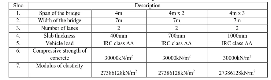
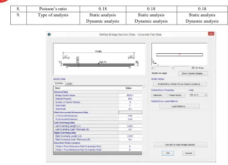
[image:2.612.71.514.610.741.2]Bridges are modelled for three different spans having same width and two lanes, details of bridges are shown in Table 1.Type of loading is adopted and suitable load combination is used according to IRC: 6-2014.Bridges are modelled and analysed in Csi Bridge. Section details and model of bridge as in Csi bridge software is shown in Fig 1 and Fig 2.Factors which affect the bridges are shown in Table 2.Bridges is analysed using static and dynamic analysis to obtain maximum bending moments and dynamic properties of bridges.
TABLE 1: Bridge details
Slno Description
1. Span of the bridge 4m 4m x 2 4m x 3
2. Width of the bridge 7m 7m 7m
3. Number of lanes 2 2 2
4. Slab thickness 400mm 700mm 1000mm
5. Vehicle load IRC class AA IRC class AA IRC class AA
6. Compressive strength of
concrete 30000kN/m2 30000kN/m2 30000kN/m2
7. Modulus of elasticity
69
©IJRASET: All Rights are Reserved
8. Poisson’s ratio 0.18 0.18 0.18
9. Type of analysis Static analysis
Dynamic analysis
Static analysis Dynamic analysis
Static analysis Dynamic analysis
[image:3.612.36.516.60.705.2]Fig. 1: Section details of 4m span bridge
[image:3.612.65.509.66.388.2]Fig. 2 Model in Csi Bridge
TABLE 2: Input data for analysis Input data for analysis
Slno. particulars
1. Density of RCC 25000kN/m2
2. Concrete grade M30
3. Live load IRC Class AA wheeled
4. Impact factor 0.173
5. Importance factor 1.2
6. Response reduction factor 3.0
7. Poisson’ ratio 0.18
8. Seismic zone Zone2
70
©IJRASET: All Rights are Reserved
V. RESULTSANDDISCUSSIONS
A. Displacement v/s Time period ( Dead load case )
Graph2: Displacement v/s time period
Graph is plotted for dead load case having displacement in meters along abscissa and Time period in seconds along ordinate. From the curve it can be told that displacement for single span bridge is higher compared to two span bridges. In case of dead load, a single span bridge has comparatively higher displacement compared to higher span bridges for lower time period. This shows that single span bridges will fail earlier than two and three span bridges, whereas two and three span bridges are more flexible comparatively.
B. Displacement v/s Time period ( Moving load case )
Graph2: Displacement v/s time period
Graph2 is plotted for moving load case having displacement in meters along x-axis and Time period in seconds along y-axis. The result obtained is almost similar to dead load case results. The above graph shows that after a particular point the displacement varies linearly and also displacement and time period increases as the span increases, this shows higher flexibility.
C. Shear force v/s displacement ( Dead load case )
71
©IJRASET: All Rights are Reserved
Graph3 is plotted for dead load case having displacement in meters along y-axis and Shear force in seconds along y-axis. From the graph it can be told that for single span bridges displacement is more than two and three span bridges for lower shear force whereas for two and three span bridges displacement is more when compared but carries has higher shear force. Considering shear force capacity short span bridges have lower shear force carrying capacity compared to two span bridges and three span bridges. Similarly two span bridges perform better than single span bridges but inferior than three span bridges.
D. Shear Force v/s Displacement (Live load case )
Graph4: Shear force v/s Displacement
Graph4 is plotted for moving load case having displacement in meters along ordinate and Time period in seconds along abscissa. According to the curves obtained it is observed that two span bridges and three span bridges shows elastic properties. Even though there is initial displacement and for the same displacement it takes more loads and finally leading to failure. Whereas from observations made it can be told that single span bridge shows negligible elasticity. There by two span bridges shows higher shear force carrying capacity for lower displacement.
VI.CONCLUSIONS
A. For dead load it can be concluded that single span bridges are more susceptible to earlier failure than two and three span bridges. From shear force carrying capacity point of view short span bridges perform poorly when compared to two and three span bridges.
B. In case of moving load, it can be concluded that more the number of spans higher will be the displacement and higher time period shows higher flexibility. From shear force carrying capacity point of view short span bridges perform poorly compared to two and three span bridges.
REFERENCES
[1] Donatello Cardone, Giuseppe Perrone, Salvatore Sofia et al., A performance-based adaptive methodology for the seismic evaluation of multi-span simply supported deck bridges, DiSGG, University of Basilicata, Potenza, Italy , Bull Earthquake Eng (2011) 9:1463–1498.
[2] L. Di Sarno, F. da Porto, G. Guerrini, P. M. Calvi, G. Camata, A. Prota, Seismic performance of bridges during the 2016 Central Italy earthquakes, Bulletin of Earthquake Engineering https://doi.org/10.1007/s10518-018-0419-4.
[3] IRC 21-2000, “standard specification and code of practice for road bridges” section III; cement concrete (plain and reinforced). [4] IRC 6-2010, “Standard Specification and Code of Practice for Road Bridges Section II” loads and stresses.
[5] IRC 5-2015, “code of standard specifications and code of practice for road bridges.”