Vehicle Tracking System based on Artificial
Intelligence and Networking
Ansh Gidwani
1, Rajiv Dahiya
2, Ruchika Doda
31,2Student, Department of Electronics and Communication Engineering, MVSIT, Sonipat
3Head of Electronics and Communication Engineering and Electrical Engineering Department, MVSIT, Sonipat 4Project Guide, Department of Electronics and Communication Engineering, MVSIT, Sonipat
Abstract: The main purpose behind this project is “Drunk driving detection”. Now a days, many accidents are happening because of the alcohol consumption of the driver or the person who is driving the
vehicle. Thus, Drunk driving is a major reason of accidents in almost all the countries in the world. Alcohol Detector in Car project is designed for the safety of the people seating inside the car. This project should be fitted / installed inside the vehicle. Now a day’s GPS tracking system is widely used all over in the words.
I. INTRODUCTION
In this paper we will show the system requirement for tracking the location and describe the implementation feature. To implement such system a GPS with high accuracy is required. In this system we send the message name TRACK to the device and the GPS of that device send the longitude and latitude to the GSM module , GSM module receive the information about longitude and latitude of that car location , further this message will be send to the user for tracking the location of car .This paper provides the concept for developing a low cost, high accuracy and user friendly system by using Google map. Improvements are proved by Google map that make high accuracy.
II. SYSTEM DESIGN AND IMPLEMENTATION
A. System Implementation
In this Chapter we are going to explain about the system design construction through Hardware and development of software. In addition, the chapter elaborates the hardware and the software stage by stage. All the operations of hardware and software are also included in this chapter. The system design of the total project is shown in below figure with simple block diagram. The sensor basically will be the input that will trigger the Arduino to control certain condition of the program. The Arduino is set to decide how the outputs will be produced and will be displayed at the display part. As the system requires the use of Arduino, the design consists of two parts, hardware and software. Hardware is constructed and integrated module by module, hardware to software for easy troubleshooting and testing.
Block Diagram 1 : Simple System Design
Arduino sensor
III. SYSTEM ARCHITECTURE
The system architecture of the auto matic output appliance can be divided into different Modules. They are:
1) Arduino Module
2) Sensory Module
3) Liquid Crystal Display (LCD) Module
4) Buzzer
5) GSM module
6) GPS module
The integration of the modules are producing the system which is more or less can be divided into two phase here the first phase is the output smart Appliance system and the second phase is the monitoring system. Figure 3.2 shows the separated phase through the boxes. The Arduino, sensory and Appliance modules are in the first phase of the system and LCD Module is in the second phase monitoring system.
A. Arduino
It is an open source, computer hardware and software company, project, and user community that designs and manufactures single-board microcontrollers and microcontroller kits for building digital devices and interactive objects that can sense and control objects
in the physical world. The Arduino is a simple yet sophisticated device which is based on Atmel’s ATmega microcontrollers. The
boards feature serial communications interfaces, including Universal Serial Bus (USB) on some models, which are also used for loading programs from personal computers. The microcontrollers are typically programmed using a dialect of features from the programming languages Cand C++. In addition to using the Arduino project provides an integrated development environment (IDE) based on the Processing language project.
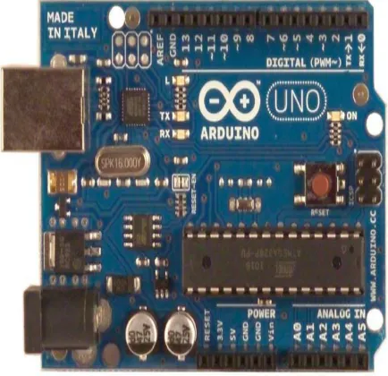
IV. ARDUINO UNO BOARD
[image:2.595.190.407.500.710.2]Arduino UNO is one of the microcontroller boards manufactured by the Arduino and it is a microcontroller board based on Atmel’s ATmega328P microcontroller. “UNO” means one in Italian and the UNO board is the latest in a series of USB (Universal Serial Bus) Arduino boards which is the reference model for the Arduino platform. The Arduino UNO board has a 16 MHz ceramic resonator, a USB connection, a power jack, an ICSP header, a reset button, 6 analog inputs and 14 digital input/output pins (of which 6 can be used as PWM outputs). It uses theAtmega16U2 programmer as a to-serial converter instead of FTDI USB-to-serial driver chip which was used in all the pre-ceding boards. The board has 32 KB flash memory of which0.5 KB is used by boot-loader, 2 KB of SRAM, 1 KB of EEPROM and 16 MHz clock speed.
A. Liquid Crystal Display
LCD is as well another output appliance here. It is used to display character in the ASCII code form which is mean the data for character that been sent by the controller to the LCD should be in 8-bit ASCII representation. The system is using the LCD to preview the safe zones as well as which of them are on fire. In the project we have used A LCD Display (16x2) and the model Number is LM016L. Normally available LCD in the market for normal displays in the projects is 2x16 pin LCD which is easily available. Talking about its specifications it has got 8 data pins, 3 control pins, and rest 5 pins for GND and VCC connections. Another LCD being used is 2x8 pin LCD but it was costly and has got better display but compromising on price and display helps to fulfill this job in a cheaper way. So 2x16 LCD is being used in the project. Its display and light intensity is also adjustable which makes it suitable to adjust for the day and night time use for better display.
[image:3.595.178.420.231.377.2]
Figure 2 :LCD Display
B. 2rows X 16 Columns Text LCD
In this project we used 2rows x 16 columns text LCD consist of two lines by 16 characters and provides basic text wrapping so that your text looks right on the display. The LCD display is compatible with the C stamp microcomputers supplies and signal levels. The LCD we are using have 16 pins out of which 4 pins are directly going to Arduino pin number 2 to 5.
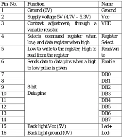
Table 1:Pin Description of 16X2 LCD Display
Pin No. Function Name
1 Ground (0V) Ground
2 Supply voltage 5V (4.7V – 5.3V) Vcc
3 Contrast adjustment; through a
variable resistor
VEE
4 Selects command register when
low; and data register when high
Register Select
5 Low to write to the register; High to
read from the register
Read/wri te
6 Sends data to data pins when a high
to low pulse is given
Enable
7
8-bit Data pins
DB0
8 DB1
9 DB2
10 DB3
11 DB4
12 DB5
13 DB6
14 DB7
15 Back light Vcc (5V) Led+
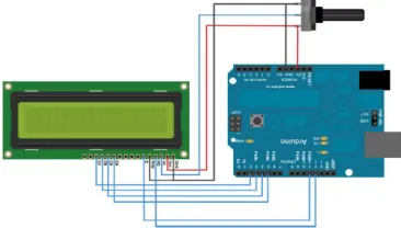
[image:3.595.174.425.440.722.2]Two pins are connected with Vcc one with ground and one with the potentiometer to set the resolution of LCD.Three control pins of LCD are also connected to Arduino. They are used for enabling LCD, performing read or write operations and to select command or data register.
Figure 3:LCD Interfacing with Arduino
C. Smoke Sensor
One of the main characteristics of fire is the smoke. Thus smoke sensors can play a vital role in detecting fire in the forest. We have used MQ-4 sensor for detecting smoke depending upon its availability and cost. MQ-4 gas sensor has high sensitivity to LPG, Propane and Hydrogen, also could be used to Methane and other combustible steam, it is with low cost and
of MQ-4 gas sensor is SnO2, which with lower conductivity in clean air. When the target combustible gas exist, the sensor’s conductivity is higher along with the gas concentration rising.
[image:4.595.236.355.377.449.2]
Figure 4:MQ-4 Sensor
D. GSM Module
Figure 5: GSM module
[image:4.595.220.382.513.638.2]V. VEHICLE TRACKING SYSTEM
Circuit Connections of this Vehicle Tracking System Project is simple. Here Tx pin of GPS module is directly connected to digital pin number 10 of Arduino. By using Software Serial Library here, we have allowed serial communication on pin 10 and 11, and made them Rx and Tx respectively and left the Rx pin of GPS Module open. By default Pin 0 and 1 of Arduino are used for serial communication but by using Software Serial library, we can allow serial communication on other digital pins of the Arduino. 12
Volt supply is used to power the GPS Module. GSM module‟s Tx and Rx pins of are directly connected to pin Rx and Tx of
Arduino. GSM module is also powered by 12v supply. An optional LCD‟s data pins D4, D5, D6 and D7 are connected to pin
number 5, 4, 3, and 2 of Arduino. Command pin RS and EN of LCD are connected with pin number 2 and 3 of Arduino and RW pin is directly connected with ground. Potentiometer is also used for setting contrast or brightness of LCD.
[image:5.595.175.419.231.588.2]Block Digram 2: Vehicle Tracking System
Figure 6: Circuit Diagram of Vehicle Tracking System Project
REFERENCES
[1] Jayashri Bangali, Arvind Shaligram, “Design and Implementation of Security Systems for Smart Home based on GSM technology”, IJSH, Vol.7, 2013. [2] Gaikwad Priyanka Rajaram, Gotraj Sonali Machindra, Jagtap Pooja Remdas , Pagare Prajakta Yaswant , Review on Implementation of Child Tracking System
Using Mobile ,Imperial Journal of Interdisciplinary Research , Vol2, Issue4, 2016
[3] A.Al.Mauzloum E.Omer, M.F.A.Abdullah, Review on Child Tracking System using Smart Phone, International Jouranl of Electronics & Communication Engineering Chaitali K.Lakde and Dr Prakash S. Prasad, Review Paper on Navigation System for Visually Impired People, International Journal of Advanced Research in Computer & Communication Engineering, Vol 4, Issue1, January 2015.]
[4] Song, M., Kim, B., Ryu, Y., Kim, Y., and Kim, S., “A design of real time control robot system using android Smartphone” The 7th International Conference on Ubiquitous Robots and Ambient Intelligence (URAI), Busan- Korea, Nov. 2010.
[5] K. Brahmani, K. S. Roy, Mahaboob Ali, April 2013, “Arm 7 Based Robotic Arm Control by Electronic Gesture Recognition Unit Using Mems”, International Journal of Engineering Trends and Technology,Vol.4
[7] S. Waldherr, R. Romero and S. Thrun, 2000, “A gesture based interface for human-robot interaction”, In Autonomous Robots in Springer, vol. 9, Issue 2, pp. 151-173Available
[8] Available:https://www.arduino.cc
[9] Available:http://wiki.iteadstudio.com/Serial_Port_Bluetooth_Module_(Master/Slave)_:_HC-05 [10] Available: http://learn.adafruit.com/adafruit-motor-shield-v2-for-arduino
[11] K. Brahmani, K. S. Roy, Mahaboob Ali, April 2013, “Arm 7 Based Robotic Arm Control by Electronic Gesture Recognition Unit Using Mems”, International Journal of Engineering Trends and Technology, Vol. 4 Issue 4 Available at: http://www.ijettjournal.org/volume-4/issue-4/IJETT
[12] Stroupe, Ashley W., Martin C. Martin, and Tucker Balch. "Distributed sensor fusion for object and Automation, 2001. Proceedings 2001 ICRA. IEEE International Conference on. Vol. 2. IEEE, 2001
[13] L. Riazuelo et al., ‘‘RoboEarth semantic mapping: A cloud enabled knowledge-based approach position estimation by multi-robot systems." Robotics,’’ IEEE Trans. Autom. Sci. Eng., vol. 12, no. 2,pp.432–443,Apr.2015 .
[14] J. Wan, S. Tang, H. Yan, D. Li, S. Wang, and A. V. Vasilakos, ‘‘Cloud robotics: Current status and open issues,’’ IEEE Access, vol. 4, pp. 2797–2807, 2016 [15] Ying Wu and Thomas S. Huang, "Vision-Based Gesture Recognition: A Review", In: Gesture-Based Communication in Human-Computer Interaction, Volume