849
©IJRASET: All Rights are Reserved
Study of Vibrational Characteristics Causing
Failure of Silencer Bracket
Aniket A. Patil 1, Prof. V. K. Kulloli 2, Prof. S. M. Jadhav 3
1
PG Student, Department of Mechanical Engineering, NBN Sinhgad School of Engineering, Ambegaon (Bk), Pune, India.
2
Asst Professor, Department of Mechanical Engineering, NBN Sinhgad School of Engineering, Ambegaon (Bk), Pune, India.
3
Professor, Department of Mechanical Engineering, NBN Sinhgad School of Engineering, Ambegaon (Bk), Pune, India.
Abstract: In automobiles exhaust system is having great importance and silencer is used to minimize the unwanted noise, the exhaust gas of high pressure and high temperature leaving internal combustion engine leads to undesirable noise and vibrations. To limit sound frequency mufflers are used in silencer assembly. Silencer has to diminish both noise and vibrations due to exhaust gases. At the same time it is exposed to high temperature, sudden vibrations and fatigue failures which cause cracks and finally failure occurs. So it is important to analyze the vibrations of silencer which help us to understand and design future projects to limit cracks and failures, improve the life and also the efficiency of silencer. This paper postulates the design and analysis of a silencer bracket for a two wheeler exhaust system. With the standard properties of material, the existing silencer and its bracket is modelled by using FEM package. The Modal analysis is then carried out for the existing design using ANSYS software. The results are compared with the reading taken on FFT analyzer. The suitable design modifications are done so as to distinguish the operating frequency from natural frequency and avoid the resonating condition by using modal analysis technique.
Keywords: Natural frequency, exhaust system, silencer bracket, resonance, Finite element method, mode shapes, FFT analyzer.
I. INTRODUCTION
Automotive silencer is an important part of the exhaust system. In automotive engine the pressure waves are generated when the exhaust valve over and again opens and radiates high pressure gas into exhaust system. These pressure pulses produce exhaust sound. As engine speed increases, pressure fluctuations increases and sound discharged is of higher frequencies. The silencer needs to permit the entry for exhaust gases while limiting the transmission of sound. This initiates vibrations in exhaust system.
Silencer has to muffle the vibrations due to exhaust gases, reduce their velocity and thus reduce the amount of noise emitted from the engines. Since the silencer is at the tail end with constrained degree for supporting along its length. The influence of vibrations is most prominent over this segment. Likewise silencer has to withstand the stresses induced due to fluctuating loads. Numbers of methods are accessible for designing, evaluating and testing of silencer.
Finite element method and experimental modal analysis have been commonly used for vibration related issues of the exhaust system. The designed bracket should be such that it not only resist the fluctuating load due to irregular road surface but also the vibration due to exhaust gases and model analysis load case without failure of bracket. The modal analysis results are validated by the experimental vibration testing. Modal analysis is necessary to determine the modes shapes and its natural frequency so as to avoid the effect of resonance.
II. LITERATURESURVEY
V.P. Patekar et al. presented work on the design analysis of an exhaust system with specified properties of the material. The exhaust system is modelled by utilizing a FEM package. The results are compared with the reading taken on FFT analyser, so as to distinguish working frequency from natural frequency and prevent the resonating condition. The silencer natural frequencies have been calculated by using the ANSYS package and by FFT analyzer. By both the method the natural frequencies are nearly same and are useful while the design of silencer to avoid the resonance. It is observed that the dynamic performance can be increased by increasing the thickness of different parts. [1]
850
©IJRASET: All Rights are Reserved
comparing the results of both the methods it is observed that the increase in natural frequency for silencer of material SUS 409L is more than the other two silencers of materials SUS 436J1L and SUS 436L. Therefore it is observed that silencer of material SUS 409L has more stiffness as compared to other two silencer materials. [2]
Somashekar G. et al. presented work on Muffler design in an automotive industry by Numerical and Experimental Modal investigation. The analysis is directed on thickness of existing muffler body by using FFT analyser. Additionally various emphases are done by changing the thickness of muffler body, perforation of baffle plates. This philosophy helps commercial users and Original Equipment Manufacturers to design and modify the silencer accordingly. Modal analysis of muffler is carried out numerically under free condition using MSC NASTRAN, and experimentally by impulse hammer testing machine. Frequency range lay between 410 to 730Hz, these frequencies are Natural frequency. The frequency obtained from both the methods is agreeing and are useful for designing the muffler.
By comparing different thickness all the models it is observed that they are meeting the performance criteria and first natural frequency of the all modals shows the same characteristics in terms of natural frequency. [3]
R. Renugadevi et al. studied that vibrations created in car engines are transferred to the silencer exhaust manifold. These continuous vibrations cause breakage in silencer ventilation system. This study manages the damping of such vibration issues with Computer Aided Engineering. In this study the vibration absorption materials are utilized as dampers and monitoring the system under various conditions for modal i.e. natural vibrations and harmonic i.e. forced vibrations response. The modelling of the system is carried out with Solid Works package and analysis using ANSYS.
The analysis methods can be implemented to reduce the risks of failure of exhaust system. It is observed that, the usage of counter weight is beneficiary as it has good vibration absorption prosperity. [4]
Vinay Gupta et al. the paper studies main stage in designing the structure of an exhaust system, with the specified characteristics of the different material, the exhaust system in this study is modelled by solid works. One of the objectives while designing a new automobile silencer is to increase its life and durable period, which can be measured in terms of its life span and mileage. The structures of automotive exhaust system and the material which can be used for the exhaust system are described. The results are compared for the deformation of silencer parts for specified materials with same exhaust thrust. This study has important role while deciding the life cycle of silencer. By vibration analysis of silencer it is observed that silencer of material SUS 436J1L have higher deformation then silencer of material SUS 436L. Hence the material SUS 436L is better option for manufacturing of silencer part because it has high life cycle. [5]
III.PROBLEMSTATEMENT
The operating frequency of vehicle under study is 60 Hz. We have to analyze the causes of vibrations in vehicle structure which results in the failure of existing silencer bracket. And modify the design of silencer bracket accordingly so as to avoid the resonating condition.
A. Objectives
1) Experimental analysis of the existing silencer bracket for Static and free vibration condition to find natural frequency by using FFT analyzer.
2) FEA modal vibration analysis of possible design alternatives to optimize the design, reduce incidence of failure and avoid vibration of silencer bracket.
B. Scope
1) In this project we have to analyze the design of existing silencer of the vehicle and location of its mounting bracket on the vehicle frame.
2) The present study is aimed to analyze the static characteristics of silencer bracket and its material.
3) Find the vibration parameters of bracket analyzed for computational simplicity. Find natural frequency by using the concept of free vibration test.
4) Modal analysis using FEA software for existing design to study the vibration parameters such as damping factors and mode shapes.
5) In this study the FFT analyzer can be used to experimentally validate the results obtained by using FEA software. And further
851
©IJRASET: All Rights are Reserved
C. Methodology
1) The study focuses on vibration characteristics of the automotive exhaust system causing failure of silencer mounting bracket. In this project we have to study the design of existing silencer and bracket of two wheel vehicles and location of its mounting bracket on the vehicle.
2) The present study is aimed to analyse the static characteristics of silencer bracket and its material. To understand the vibration parameters of bracket analysed for computational simplicity. Then find natural frequency of the existing design by using the concept of free vibration test.
3) The Geometric modelling of the existing silencer bracket is done by using CAD software which is subjected to free-free vibration boundary conditions for analysing specimen.
4) Modal analysis is done by using FEA software for existing design to study the vibration parameters such as damping factor, natural frequency and mode shapes. The Fast Fourier Transform analyser is used to experimentally validate the results which are obtained by using FEA software.
5) Making suitable design modifications in the silencer bracket so that the operating frequency does not match with the natural frequency and the resonance is avoided.
6) Then FEA modal vibration analysis of possible design alternatives is to be performed so as to optimize the design and reduce
the incidence of failure.
IV. DESIGN
The Bolted joint is a very popular method of fastening components together. Because of large stress concentrations, joints can become a source of weakness if not designed properly. By considering the maximum load which comes on silencer bracket is 400 N by taking into consideration the weight of Silencer and factor of safety for person weight due to misuse which is acting vertically at a distance of 20mm from the face of chassis of a two wheeler. Vertical face of bracket is secured to two wheeler chassis by a bolt. From the design calculations it is observed that for safe design of silencer bracket assembly and the bracket to carry load which comes while supporting the silencer without any failure the minimum width and thickness of silencer mounting bracket should be 14 mm and 3 mm respectively.
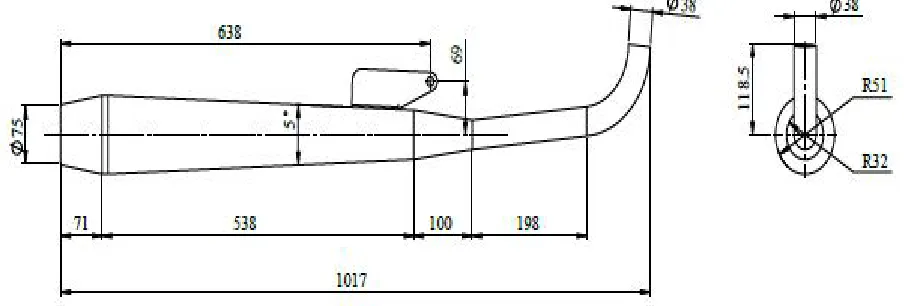
[image:3.612.85.537.463.616.2]The CAD geometry of existing model has been completed using CATIA V5 software. The step file of model is then imported to ANSYS 19.1 software to analyze the existing design, find natural frequency and study the mode shapes. The figure below shows the 2D drawing with dimensions of existing silencer bracket assembly.
Fig. No. 1: CAD drawing of existing silencer bracket assembly
A. Material Properties
1) The material used for Silencer is SUS 436L and its bracket is SUS 409L, with reference from JFE steel corporation catalogue.
2) The SUS 436L is having very good corrosion resistance as it contains 16% Chromium and 0.75% Molybdenum of total composition.
3) The material SUS 409L is having good weldability with 11.7% of Chromium composition hence it is used for making silencer
852
©IJRASET: All Rights are Reserved
Table No. 1: Material properties
Mechanical Properties SUS 436L SUS 409L
Tensile yield strength 270 Mpa 240 Mpa
Tensile ultimate strength 500 Mpa 450 Mpa
Modulus of Elasticity 200 Gpa 200 Gpa
Density 7850 kg/ 3 7850 kg/ 3
Poissons ratio 0.3 0.3
V. FINITEELEMENTANALYSIS
The Finite element analysis is carried out to validate the results obtained from FFT analyser. The CAD modelling of existing Silencer and its bracket is done by using CATIA V5 software by taking actual dimensions.
[image:4.612.146.463.87.196.2] [image:4.612.63.546.238.375.2]
Fig. No. 2: CAD Model of Existing Silencer bracket Fig. No. 3: Meshing of CAD model in ANSYS
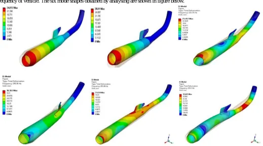
The natural frequency obtained from modal analysis of the existing silencer bracket design comes in the range of operating frequency of vehicle. The six mode shapes obtained by analysing are shown in figure below.
[image:4.612.47.566.418.707.2]
853
©IJRASET: All Rights are Reserved
[image:5.612.220.388.113.214.2]The Natural frequencies and mode shapes of existing bracket design obtained from analysis are shown in table below.
Table No. 2: Natural frequency of existing design
Mode number Frequency (Hz)
1 32.482
2 105.8
3 222.35
4 295.95
5 455.04
6 833.3
From the values it is observed that the natural frequency obtained from FEA matches with the results obtained from experimental results. Hence the results are validated and we can use the FEA method to modify the design and avoid the resonating condition of the silencer. Numbers of iterations are performed to obtain the best possible design.
A. Iteration Number 1
The modification in existing silencer bracket is done to avoid the resonating condition by increasing the length of bracket and hence the support to the silencer as shown in figure. The CAD model of this modified design is created which is then used for modal analysis. The bonded contact between the modified bracket and silencer is given as the bracket is welded to silencer as shown in the figure below.
[image:5.612.50.562.347.467.2]
Fig. No. 5: CAD model of Iteration 1 modified bracket Fig. No. 6: Contact region for Iteration 1 design
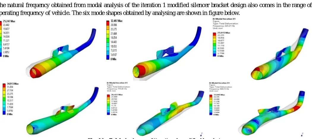
The natural frequency obtained from modal analysis of the iteration 1 modified silencer bracket design also comes in the range of operating frequency of vehicle. The six mode shapes obtained by analysing are shown in figure below.
[image:5.612.47.572.486.721.2]
854
©IJRASET: All Rights are Reserved
The Natural frequencies and mode shapes of modified bracket design obtained from analysis in Iteration 1 are shown in the table below.
Table No. 3: Natural frequency of iteration 1 modified design
Mode number Frequency (Hz)
1 56.149
2 197.69
3 223.21
4 309.77
5 715.61
6 828.13
From the above values it is observed that the natural frequency obtained from FEA for modified bracket also comes below and in the range of operating frequency. Hence the design may also create resonance and it is unsafe. So it is necessary to carry out further iterations to obtain the better and safe design.
B. Iteration Number 2
The modification in design of Iteration 1 modified silencer bracket is done as its frequency was coming in the range of operating frequency. Hence the support to the silencer as well as to the bracket is given by adding ribs as shown in figure. The bonded contact between the modified bracket and silencer it is welded to silencer is shown in the figure below.
[image:6.612.56.562.346.466.2] [image:6.612.46.568.517.723.2]
Fig. No. 8: CAD model of Iteration 2 modified bracket Fig. No. 9: Contact region for Iteration 2 design
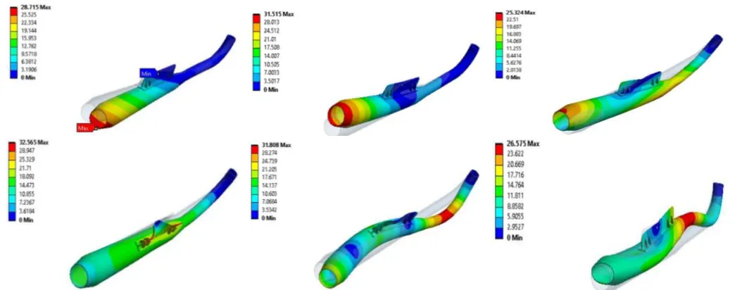
The natural frequency obtained from modal analysis of the iteration 2 modified silencer bracket design does not come in the range of operating frequency of vehicle. The six mode shapes obtained by analysing are shown in figure below.
855
©IJRASET: All Rights are Reserved
The Natural frequencies and mode shapes of modified bracket design obtained from analysis in Iteration 2 are shown in the table below.
Table No. 4: Natural frequency of iteration 2 modified design
Mode number Frequency (Hz)
1 88.302
2 218.61
3 222.24
4 453.45
5 835.82
6 925.57
From the above values it is observed that the natural frequency obtained from FEA for modified bracket in iteration 2 does not comes in the range of operating frequency. Hence the design is free from resonance. So we can say that the design of silencer bracket in iteration 2 is safe and can it be used in place of existing design.
VI.EXPERIMENALANALYSIS
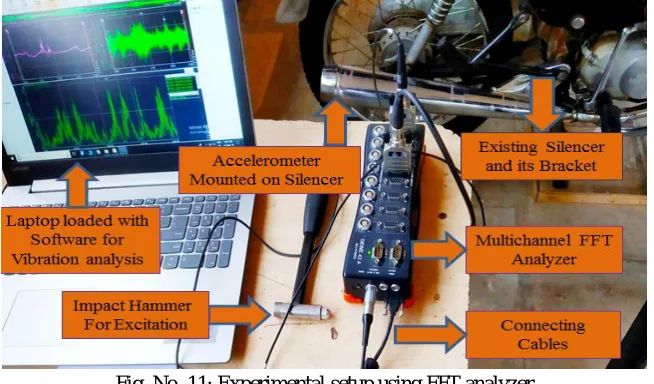
[image:7.612.144.471.320.512.2]The experimental analysis on the existing silencer bracket design is done by using Fast Fourier Transform analyzer commonly known as FFT analyzer is shown in the figure below.
Fig. No. 11: Experimental setup using FFT analyzer
A. The above experimental setup is used to find the natural frequency of the silencer bracket. Initially the test is taken on the vehicle in running condition when it is neutral to find the operating frequency. In this case the vehicle is accelerated and no excitation force is given by impact hammer.
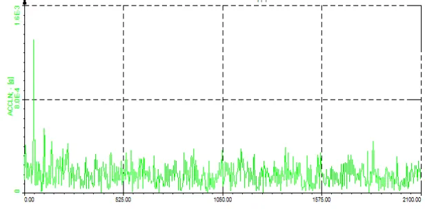
[image:7.612.151.465.601.717.2]B. The results are then observed by placing the accelerometer at different locations on the silencer. The figure below shows the graphical results of operating frequency of vehicle obtained from the FFT analyzer.
856
©IJRASET: All Rights are Reserved
[image:8.612.225.388.128.232.2]C. The table below shows the operating frequency of vehicle observed by varying the location of accelerometer on the silencer. This frequency can be used as a reference to design the silencer bracket further for avoiding the resonating condition and reduce the incidence of failure.
Table No. 5: Operating frequency of vehicle
Mode number Frequency (Hz)
1 24.41
2 35.79
3 48.83
4 51.92
5 57.61
6 61.04
D. From the above table it is observed that the operating frequency of Silencer is about 60 Hz. Hence the natural frequency of silencer bracket design should be above the operating frequency to avoid vibrations.
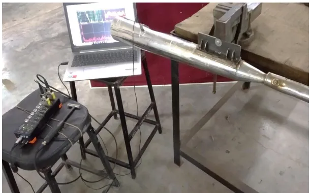
E. The FFT analyzer is then used to find the natural frequency of existing silencer bracket design. In this case the Hammering location is fixed at tail end of the silencer and excitation is provided with the help of impact hammer. The results are observed simultaneously by placing the accelerometer at different locations on the silencer.
F. The figure below shows the graphical results of natural frequency of the existing silencer bracket design obtained by using FFT analyzer. As the hammering is done at the extreme end of the silencer the accelrometer is to placed at all the other nod points on the silencer to take the reading.
[image:8.612.151.459.375.527.2]G. This results are then plotted in table for making comparison with the FEA results for validation and modifications.
Fig. No. 13: Experimental analysis for Natural frequency of existing design
H. The table below shows the natural frequency of existing design observed by varying the location of accelerometer on the silencer and in this case the hammering is done at the tail end of the silencer with the help of impact hammer.
Table No. 6: Natural frequency of existing design using FFT analyzer
Mode number Frequency (Hz)
1 40.83
2 105
3 222.2
4 244.1
5 386
[image:8.612.225.390.607.704.2]857
©IJRASET: All Rights are Reserved
I. From the above table it is observed that the results of natural frequency for existing silencer bracket design obtained experimentally matches with the FEA results and are in the range of operating frequency of vehicle. Hence the results obtained from FEA are validated with the experimental results.
J. When natural frequency of any object matches with its operating frequency then resonance is created. So the modification is to be done by carrying out iterations and find the best possible design alternatives such that the natural frequency of modified design does not come in the range of operating frequency vibrations due to resonance is avoided.
VII. EXPERIMENALTESTINGOFMODIFIEDDESIGN
A. The results of modal analysis for Iteration number 2 modified silencer bracket obtained from Finite element analysis shows that the natural frequency is above and does not come in the range of operating frequency of the vehicle.
B. It is observed that increase in mass increases the stiffness and hence the natural frequency the same principle is implemented while modifying the design and iteration 2 design is observed to be safe.
[image:9.612.153.461.289.469.2]C. This modified design in which support is given to the silencer as well as to the mounting bracket by adding ribs is fabricated as shown in the figure below.
Fig. No. 14: Fabrication of Iteration 2 Modified design
D. The FFT analyzer is then used to carry out the experimental analysis so as to validate the results of natural frequency obtained from FEA. The bracket is bolted to a rigid body for providing fixed support as shown in figure below.
[image:9.612.153.458.524.714.2]858
©IJRASET: All Rights are Reserved
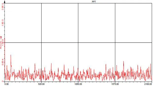
[image:10.612.158.460.121.298.2]E. The figure below shows the graphical results of natural frequency of the modified silencer bracket design obtained by using FFT analyzer. As the hammering is done at the extreme end of the silencer the accelerometer is to be placed simultaneously at all the other node points on the silencer.
Fig. No. 16: Experimental analysis for natural frequency of modified design
F. These results are then plotted in table for making comparison with the FEA results for validation purpose. The table below shows the natural frequency of modified design observed by varying the location of accelerometer on the silencer.
Table No. 7: Natural frequency of modified design using FFT analyzer
Mode number Frequency (Hz)
1 87.89
2 212.3
3 234.4
4 432.19
5 859.73
6 910.5
G. From the above table it is observed that the results obtained by experimental analysis of the modified silencer bracket design agree with the FEA results. The natural frequency of these modified silencer bracket design is above and does not comes in the range of operating frequency of vehicle. Hence resonance is avoided and design is observed to be safe.
VIII. RESULTSANDDISCUSSION
A. The results obtained from Experimentation shows that the Existing design of silencer bracket is unsafe, as the natural frequency matches with the operating frequency of vehicle. The operating frequency of vehicle is about 60 Hz. The results obtained from FFT analyser are validated with the FEA results. This shows that we can go with FEA method for modifying the design and modal analysis can be done to find its natural frequency and avoid the resonating condition.
B. The iterations of design modification are carried out to obtain the best possible design alternatives. The iteration 1design modification shows that the length of bracket is increased to increase the support for silencer, but when it was tested on FEA the frequency was coming in the range of operating frequency which is unsafe. So the further iteration was performed in which the Support was given to silencer by increasing the bracket length and also the support was added to bracket by implementing ribs on the bracket.
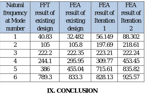
C. The table below shows the comparison between the results of natural frequency for existing design tested on FFT analyser with
859
[image:11.612.185.432.91.250.2]©IJRASET: All Rights are Reserved
Table No. 8: Comparison between FFT and FEA results for Existing and Modified design
Natural frequency at Mode number FFT result of existing design FEA result of existing design FEA result of Iteration 1 FEA result of Iteration 2
1 40.83 32.482 56.149 88.302
2 105 105.8 197.69 218.61
3 222.2 222.35 223.21 222.24
4 244.1 295.95 309.77 453.45
5 386 455.04 715.61 835.82
6 789.3 833.3 828.13 925.57
IX.CONCLUSION
A. The silencer and its bracket natural frequencies can be determined by utilizing the ANSYS package and by FFT analyzer. By
both the technique the natural frequencies can be obtained and compared which is useful while the designing of silencer and its bracket to avoid the resonance.
B. The silencer bracket vibration analysis is carried out experimentally using FFT analyzer and it is observed to be unsafe due to resonance. These results are then compared with FEA results to validate the results.
C. It is observed that the operating frequency of vehicle is 60 Hz by experimentally performing test on vehicle using FFT analyzer. Hence to avoid resonating condition the silencer bracket is to be designed such that its natural frequency is above the operating frequency. This will help in avoiding the vibrations and reduce incidence of failure.
D. The modified design in second iteration by adding rib support to silencer bracket is observed safe as its first natural frequency 88.3 Hz is above operating frequency and does not come in the range of operating frequency.
E. The weight of existing silencer bracket design is 5.1 kg and with the modification in design the weight has increased to 5.26 kg. Though the weight has increased by 4 % of silencer bracket assembly and 126 grams of bracket, the natural frequency of modified design observed is above the operating frequency which avoids the resonance. By considering the durability of the modified bracket due to reduction in vibrations, the increase in cost of bracket is negligible.
F. Hence for silencer vibration analysis we can use FEM technique portrayed in above references. The FEM simulation is superior
method over conventional trial and error and experimental method for predicting the errors while designing with the help of modal analysis.
X. FUTURESCOPE
A. Vibration being a non-saturating subject hence there is always the scope for improvement. Further analysis can be done by changing silencer bracket material.
B. The change in performance and aesthetics of modified design can be analysed as with change in material there will be change in its mechanical properties.
XI.ACKNOWLEDGEMENT
It is indeed a great pleasure and moment of immense satisfaction for me to present a Research paper on “Study of Vibrational Characteristics Causing Failure of Silencer Bracket” amongst a wide panorama that provided us inspiring guidance and encouragement, I take the opportunity to thanks those who gave us their indebted assistance. I wish to extend my cordial gratitude with profound thanks to our internal guide Prof. V. K. Kulloli. It was his inspiration and encouragement which helped in completing my work.
I am also thankful to Prof. S. M. Jadhav, PG Co-ordinator for his overwhelming support and invaluable guidance. My sincere thanks and deep gratitude to Head of Department, Prof. D. H. Burande and other faculty members; but also to all those individuals involved both directly and indirectly for their help in all aspect of the Project.
860
©IJRASET: All Rights are Reserved
REFERENCES
[1] V.P. Patekar and R.B. Patil, “Vibrational Analysis of Automotive Exhaust Silencer Based on FEM and FFT Analyzer”, International Journal on Emerging Technologies, ISSN: 2249-3255, July 2012.
[2] Mukesh D. Bankar, M. R. Buchade, “Study and Vibration Analysis of Two Wheeler Silencer”, International Journal of Engineering Research & Technology, ISSN: 2278-0181, Volume 6, Issue 08, August 2017.
[3] Somashekar G, A. M. Prakasha, Noor Ahamd R, K. S. Badrinarayan, “Modal Analysis of Muffler of an Automobile by Experimental and Numerical Approach”, International Journal of Recent Research in Civil and Mechanical Engineering, Vol. 2, Issue 1, pg: 309-314, September 2015.
[4] R. Renugadevi, V. Rajkumar, “Modelling And Analysis Of Damping Effect In Exhaust System Using Ansys”, International Journal of Aerospace and Mechanical Engineering, ISSN: 2393-8609, Volume 3, October 2016.
[5] Vinay Gupta, Dhananjay Singh, “Vibrational Analysis Of Exhaust Muffler”, International Journal of Scientific & Engineering Research, ISSN 2347-6435, Volume 4, Issue 6, June 2013.
[6] Sunil, Suresh P. M, “Modelling Experimental Modal Analysis of Automotive Exhaust Muffler Using Fem and FFT Analyzer”, International Journal of Recent Development in Engineering and Technology, ISSN 2347-6435, Volume 3, Issue 1, July 2014.