©IJRASET: All Rights are Reserved
535
Head Mounted Display
Onkar Gagare1, Chinmay Tarwate2, Rupesh Jaiswal3
1, 2, 3
Department of E&TC, Pune Institute of Computer Technology
Abstract: Virtual reality is a concept of realistic and immersive simulation of a 3D-based environment generated by an interactive software and hardware. They can be displayed either on a computer monitor, a projector screen, or with a virtual reality headset (HMD). The first commercial headset was released in the 1990s by Sega. Though it was not very successful, it was the first relevant product to be introduced to the public. Ever since, there has been a lot of research done on virtual reality products, the most relevant being Oculus.
I. INTRODUCTION
Virtual reality is an extensive topic of Electronics and Telecommunications pertaining to the field of embedded systems. Digital image processing deals with image acquisition, processing, enhancement of images based on user requirements.
The foundation of virtual reality dates back to the 1950s. The first device was dubbed as an “experience theatre” which could show short films that would engage the different senses. The first HMD was created in 1970, which was primitive both in terms of user interface and realism.[1] It could only show wire-frame models and it was so heavy that it had to be attached to the ceiling. Virtual simulation using computers was initiated in 1990 but was very limited due to the low computing powers of early computers. Due to this huge cost, it was only used in specific training modules such as medical, flight simulations. The first head-tracking HMD was designed by Sega in the early 1990s. [2] HMD, BOOM, CAVE are common virtual environments now and virtual globe is an upcoming technology in virtual environments; in the follow sections, we describe about these VEs, separately. [3] OpenGL will be used for video processing.[4] MPU6050 is interfaced using I2C communication to provide parameters of head movement.
In recent times, there have been many successful head-tracking HMDs, notably Oculus and HTC. They have been able to reduce latency greatly and run high fps videos, all this while bringing the costs into an affordable range.
Even though virtual reality is a trend right now, the HMDs available in the market are very expensive. Since the potential of this technology is massive, we must find ways to make the technology affordable for the masses. Hence, we decided to focus on the cost-efficiency in the making of the device.
This is a fully integrated HMD (Head Mounted Display) for virtual reality using Raspberry Pi 3 aiming to construct the display in an optimal cost with limited scope for single screen display.
II. TECHNICAL APPROACH
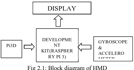
As this project aims to construct head mounted display in an optimal cost, the following components/functional blocks are required: Gyroscope and accelerometer sensor (MPU 6050), Development board (Raspberry Pi 3), Lens, LCD Display. Technical details are as follows:
1) Gyroscope and Accelerometer: MPU 6050 sensor is used for detecting head movement in 3 axis. This values are used to change video angle on LCD Display.
2) Development Board: Raspberry Pi 3 Model B is used as a development board. This will receive data from sensor and process video to be displayed on LCD Display.
3) Lens: Lens are used to adjust focus as our LCD Display will be far near for our eyes. Lens will also reduce screen door effect. 4) LCD Display: LCD Display is used to display stereoscopic video.
III. ARCHITECTURE
©IJRASET: All Rights are Reserved
536
Fig 2.1: Block diagram of HMDA. Raspberry Pi 3 Model B
This is a development board used to configure different components simultaneously. Output from sensors is given to Raspberry Pi 3 which will change the video output on LCD display according to the data received from sensors.
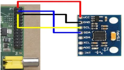
B. Sensor (MPU6050)
The MPU-6050 is the world’s first integrated 6-axis Motion Tracking device that combines a 3-axis gyroscope, 3-axis accelerometer, and a Digital Motion Processor (DMP) all in a small 4x4x0.9mm package. With its dedicated I2C sensor bus, it directly accepts inputs from an external 3-axis compass to provide a complete 9-axis Motion Fusion output.
The MPU-6050 features three 16-bit analog-to-digital converters (ADCs) for digitizing the gyroscope outputs and three 16-bit ADCs for digitizing the accelerometer outputs. With all the necessary on-chip processing and sensor components required to support many motion-based use cases, the MPU-6050 uniquely enables low-power Motion Interface applications in portable applications with reduced processing requirements for the system processor.
Features 1) Gyroscope
a) Digital-output X-, Y-, and Z-Axis angular rate sensors (gyroscopes)
b) External sync signal connected to the FSYNC pin supports image, video and GPS synchronization
c) Integrated 16-bit ADCs enable simultaneous sampling of gyros
d) Improved low-frequency noise performance
e) Gyroscope operating current: 3.6mA
f) Standby current: 5µA
g) Factory calibrated sensitivity scale factor h) User self-test
2) Accelerometer
a) Digital-output triple-axis accelerometer
b) Integrated 16-bit ADCs enable simultaneous sampling of accelerometers while requiring no external multiplexer
c) Accelerometer normal operating current: 500µA
d) Orientation detection and signaling
e) Tap detection
f) User-programmable interrupts
g) High-G interrupt
h) User self-test
GYROSCOPE & ACCELERO METER DISPLAY DEVELOPME NT KIT(RASPBER
©IJRASET: All Rights are Reserved
537
C. LCD displayLCD display is used to display the video provided by raspberry pi. The video used for virtual reality is a 3D video, termed as stereoscopic video. It uses a technique called stereopsis to enhance the depth of the image to engender a 3D look. Most stereoscopic methods present two offset images separately to the left and right eye of the viewer. These two-dimensional images are then combined in the brain to give the perception of 3D depth. This technique is distinguished from 3D displays that display an image in three full dimensions, allowing the observer to increase information about the 3-dimensional objects being displayed by head and eye movements.
There are three techniques which are used to achieve stereoscopic video: 1) Color shifting (anaglyph)
2) Pixel subsampling (side-by-side, checkerboard, quincunx)
3) Enhanced video stream coding (2D+Delta, 2D+Metadata, 2D plus depth)
Fig 2.4: LCD Display
D. Lens
Google Cardboard (I/O 2015 edition) contains custom designed, 80o FOV, 34 mm diameter lenses.
Fig 2.5: Google Cardboard (I/O 2015 edition) lenses.
IV. RESULT OF PROJECT AND DISCUSSION
[image:3.612.208.414.595.712.2]The project was started with the software part by installing the necessary packages required for image processing. Pi3D was installed on Ubuntu 16.04 along with Python 3.4 as the programming language. Pi3D is a Python module that gives access to the power of the Raspberry Pi GPU. It enables both 3D and 2D rendering. Along with the software installation on the laptop, Pi3D was also installed on Raspberry Pi 3 model B. Two more software were installed for interfacing Raspberry Pi with the laptop – Xming and Putty. These two software generated a UI on the laptop. Then, MPU6050 was connected to the Raspberry Pi.
©IJRASET: All Rights are Reserved
538
sudo apt-get install i2c-toolssudo i2cdetect -y 1 (for a Revision 2 board) sudo apt-get install python-smbus
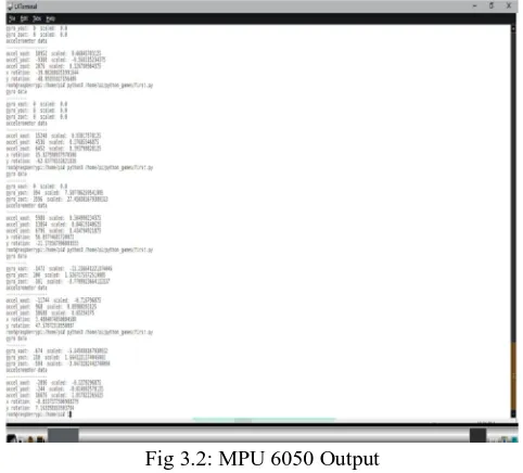
[image:4.612.185.426.144.362.2]These were the prerequisites needed for performing the python code for fetching the gyroscope and accelerometer output as follows –
Fig 3.2: MPU 6050 Output A. Pi3D
Pi3d is a Python module that aims to greatly simplify writing 3D in Python whilst giving access to the power of the Raspberry Pi GPU. It enables both 3D and 2D rendering and aims to provide a host of exciting commands to load in textured/animated models, create fractal landscapes, shaders and much more.
The pi3d module runs on platforms other than the Raspberry Pi (On Windows using pygame, on linux using the X server directly and on Android using python-for-android) and runs with python 3 as well as 2. The OpenGLES2.0 functionality of the Raspberry Pi or Android is used directly or via mesa or ANGLE on 'big' machines. This makes it generally faster and opens up the world of shaders that allow effects such as normal and reflection maps, blurring and many others.
Figure 3.3: Environment created using OpenGL
[image:4.612.189.425.473.637.2]©IJRASET: All Rights are Reserved
539
Fig 3.4: Video OutputB. Using A Complementary Filter To Combine Accelerometer And Gyroscopic Data
[image:5.612.181.393.313.470.2]The following graph show a simple rotation in X of roughly 90-100 degrees. The red line shows the accelerometer data and as we can see from the spikes it's a noisy data set. The green line shows the rotation angle calculated from summing the individual angles read from the gyroscope. While thisdata is less noisy it is prone to drift over time, the gyroscope doesn't return back to zero when not moving
Figure 3.5: Complementary filter output plot
The blue line shows the complementary filter at work. It combines the two data sets by merging fast rotations from the gyroscope with the slower trends from the accelerometer and we get the best of both worlds.
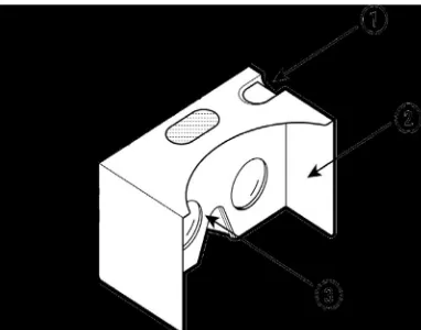
V. CONSTRUCTION OF HARDWARE SETUP
1) Step 1: Removing phone holding portion of cardboard VR, so as to adjust the screen in front of lenses.
[image:5.612.176.367.570.720.2]©IJRASET: All Rights are Reserved
540
2) Step 2: Putting HMD together, the cardboard is fitted to the LCD Screen [image:6.612.216.386.275.484.2]Figure 4.2: LCD screen and raspberry pi
Figure 4.3: Enclosing the VR cardboard and LCD screen in a single box
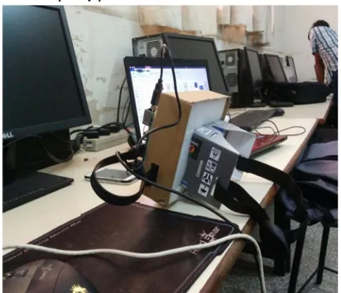
3) Step 3: Connecting LCD screen with Raspberry pi and MPU6050.
[image:6.612.182.425.512.721.2]©IJRASET: All Rights are Reserved
541
VI. CONCLUSION
Since the last few years, computer animation seems to be more based on dynamic simulation methods and physics. With the advent of VR, it feels like we are in a 3-D computer generated environment. The screen door effect and ghosting will be decreased which will reduce the switching lags experienced with the use of MPU6050, which has a sampling rate of 1 KHz. The orientation error was reduced by making the values obtained more in sync with the real time movements of the host.
VII. FUTURE SCOPE
The 3D environment created can be interfaced with haptic technology to give a real time experience. More sensors can be interfaced to provide various gesture outputs. This can also be used for immersive films and video games. Wherever it is too dangerous, expensive or impractical to do something, virtual reality comes into the picture. From trainee fighter pilots to medical applications trainee surgeons, virtual reality allows us to take virtual risks to gain real world experience. As cost of virtual reality headset comes down, more applications in the field of education and productivity applications are expected.
Virtual worlds combine the power of 3D graphics and the internet, giving users the ability to create new versions of themselves literally within a virtual world. Second life, arguably the most popular of these games, has seen massive successes, which includes creating millionaires out of some of their long-time and most dedicated players. This is made possible by their own currency and exchange rates.
This project can also be used for treatment of agoraphobia which is an anxiety disorder characterized by symptoms of anxiety in situations where the person perceives the environment to be unsafe.
REFERENCES
[1] International Journal of Scientific & Engineering Research, Volume 4, Issue 4, April-2013
[2] International Journal of Modern Engineering Research (IJMER)Vol.3, Issue.2, March-April. 2013 pp-1139-1145 [3] “Virtual Reality development on the Raspberry Pi, in Python”: https://github.com/WayneKeenan/python-vrzero