Power Quality Improvement of Grid Connected
Wind Energy System by using STATCOM-Control
Scheme
Mohd. Mudabbir Ul Hasan Mughni1, Aquib Mehdi Naqvi2, Dr. A. S. Pandey3, Dr. R. P. Payasi4, Dr. S. K. Sinha5
1, 2
Student, 3, 4, 5Professor, EED, KNIT, Sultanpur, U.P India
Abstract: With the increase in demand for Electricity due to increase in population and industrialization, the generation of power to meet the demand is really a challenge nowadays. It has become necessary to utilize renewable energy resources like wind, biomass, hydro co-generation to meet the energy needs etc. In this suggested scheme we have developed a model with grid integrated wind energy generating system and nonlinear load in MATLAB/SIMULINK.
Injecting wind energy into the power grid affects the quality of electricity. The most important power quality problems are voltage swelling, voltage swelling, harmonics, flicker, weak power factor by the source, etc. Based on measurements and standards that follow in accordance with the guidelines specified in IEC-61400 (International Electrotechnical Commission ), the performance of a wind turbine and, therefore, the quality of electricity is determined.
In this proposed scheme, the FACTS device STATCOM (static compensation) is connected at the PCC with the battery power storage system (BESS) to alleviate power quality problems. The Battery Energy Storage System is integrated to support the real power source during wind power fluctuations, also it helps rapid injection of reactive power at PCC.
Keywords: Static Compensator (STATCOM), Battery Energy Storage System (BESS), International electro-technical commission (IEC), THD and Power Quality Point of Common Coupling (PCC).
I. INTRODUCTION
Today the demand for energy is rising rapidly, due to population growth and world economic development leading to the increased environmental impact on conventional plants.
Therefore renewable energy sources must be used to meet energy demands and to have communal development and expansion of growth. In recent years, among other renewable energy sources, wind energy has received increasing attention as a clean, safe and economical resource.
So to use wind power effectively this grid connection is necessary to be aware of its potential to significantly alleviate current day problems such as energy demand along with atmospheric pollution. But the integration of wind power into the grid introduces issues with electricity quality, which is largely comprised of voltage regulation and reactive power compensation. Electricity quality is an important customer-oriented measure and is of paramount importance to the wind turbine.
In wind power generation, most induction generators are used because of their financial capacity and stability. For magnetization of induction generators, they absorb reactive power from the grid which they are connected. The active force generated by the induction generator varies due to the fluctuation of the natural wind and this variation can jointly affect the absorbed reactive power and the terminal voltage of the induction generator. Integrating wind energy into a grid affects the system's electrical quality.
II. POWER QUALITY STANDARDS, ISSUES AND ITS CONSEQUENCES
A. International electro-technical commission guidelines
According to IEC 61400-21 the relevant parameters for characterizing Power Quality of wind turbine are The standard norms are specified.
1) IEC 61400-21: Measuring the power quality feature of grid linked wind turbine.
2) IEC 61400-13: Wind Turbine—measuring procedure in determining the power performance.
B. Harmonics
Power electronic converters cause harmonics in the power system. Harmonic voltage and current must be according to the IEC-61400-36 guidelines. Fast switching gives a significant reduction in the current of lower-order harmonics, while higher-order harmonics are filtered out by using filter.
C. Wind Turbine Switch in Power System
The way in which the gas is connected to the output system with the power system influences the quality of the power. Thus, the function and its effects on the power system depend on the structure of the adjacent electrical network.
D. Voltage Variation
The Wind generator output is not always constant even during normal operation, because the wind velocity is not always constant. Because of continuously changing wind speed the generator torque developed is also continuously varying. The variations developed in generator torque results in voltage variation issue .As we know that the voltage is directly related to real and reactive power hence the variations in voltage results in the real and reactive power variations. There are few types of voltage variations which are given below:
1) Voltage sag/Voltage dips: When the RMS voltage is below the nominal voltage by10 to 90% for 0.5 cycles to 1 minute. The acceptable voltage dips limiting value is less than 3%.
2) Voltage swell: When RMS voltage exceeds the nominal voltage by 10 to 80% for 0.5 cycles to 1 minute, it is called "swell". The allowable voltage dips are less than 3% of the limiting value.
3) Short interruptions: Short interruptions (called "discontinuities" in some standards) at the consumer's supply, which last no longer than 1 minute (which for energy quality include short-term voltage reductions of less than 0.1 pu) are usually caused by the operation of automatic closing systems.
4) Long duration: Variation include root mean square deviations of power frequency greater than 1 minute. ANSIC-84.1 (American National Standards for Power Systems and Devices) determines the expected steady-state voltage tolerance of a power system. When the ANSI threshold exceeds 1 minute, a longer duration of voltage change is predicted.
In order to work properly, electronic devices require a constant range within the voltage to flow. Power surges, sags, transients, and momentary interruptions can cause a voltage to fluctuate outside this range. Power quality problems can be caused by external events, such as lightning strikes can impact power quality but causes can also include starting and stopping of heavy equipment, circuit overloads, or improper wiring. Some loads that cycle on or off can cause surges that can gradually degrade the internal circuitry of sensitive electronic equipment.
III. GRID COORDINATION RULE
The grid quality features and limitations are provided for references that users and the utilities network can expect. According to the Economic Energy Act, the transport network operator is responsible for establishing and operating interconnected systems. The rules for achieving network operation of the wind generation system in the distribution network are defined in accordance with ICE 61400-21.
A. Voltage Dips B. Voltage Rise C. Harmonics D. Grid Frequency E. Flicker
IV. TOPOLOGY FOR POWER QUALITY IMPROVEMEN
Fig.1: Grid-connected system for power quality improvement
A. Wind Energy Generating System
Wind generation is based on steady-state speed topologies with pitch control turbine. The induction generator is used in a modular circuit because of its simplicity, it does not require a separate field circuit, it can accept constant and variable loads and provides natural protection against short circuit. The existing capacity of the wind energy system is shown in (1).
3 wind
2
1
P
AV
wind… (1)
Where is the air density in (kg / m3) and A is the area swept out by turbine blade in meters, VWIND is the wind speed in m/s. It is impossible to extract all the kinetic energy of the wind, and therefore consumes a small part of the energy in the wind, called the power coefficient CP, for the wind turbine, and is presented in (2).
P
mech
C
PP
wind … (2)Where CP is the power coefficient, depends on type and operating condition of wind turbine.
Power coefficient can be denoting as a function of tip speed ratio and pitch angle. The mechanical power produce by wind turbine is given in (3).
wind P
C
V
R
2 3mech
2
1
P
… (3)
Where R is the radius of the blade (m).
B. BESS-STATCOM
C. System Operation
Power network model of the proposed grid connected system is shown in Fig.2.The system consists of wind energy generation system and battery energy storage system with STATCOM. To voltage regulation, the battery energy storage system (BESS) is worked as an energy storage element. The BESS will naturally sustain DC capacitor voltage constant and is best suited in STATCOM since it quickly injects or absorbed reactive power to stabilize the grid system. BESS can be used to level the power variation by charging and discharging operation. The battery is connected in parallel with the DC-link capacitor of STATCOM.
Fig.2: System operational scheme in grid system
STATCOM is a three-phase voltage source inverter that has capacitance on its DC-link connection and is connected to point of common coupling. The STATCOM injects current of variable magnitude and frequency component at the bus of common coupling. The shunt connected STATCOM with battery energy storage system; Non-linear load and induction generator are altogether connected at PCC (point of common coupling) in the grid system. The STATCOM output is varied according to the controlled strategy, so as to maintain the power quality norms in the grid system. The current control approach is included in the control scheme that defines the function of the STATCOM in the power system. Using an Insulated Gate Bipolar Transistor (IGBT) by a STATCOM, it is expected to support reactive power input to the generator and nonlinear load on the grid system.
V. CONTROL SCHEME
The control method is based on the injection of current into the network using a "Bang-Bang controller" which is works on hysteresis current-control method. This controller is also acknowledged as the 2-states controller. Using this technique, the controller maintains an oscillating control system between the boundaries of the hysteresis region and receives the proper switches for STATCOM operation. The control system diagram is shown in Figure 3 for the switching signal to STATCOM.
A. Grid Synchronization
In 3-phase balanced system, at the sampling frequency the RMS voltage source amplitude is calculated with the help of source phase voltage (Vsa , Vsb,Vsc) and is expressed, as sample template Vsm , sampled peak voltage, as in (4).
21 2 2 2 3 2
sa sb sc
sm V V V
V
… (4)
The unit vectors (in-phase) are obtained from AC source-phase voltage and the RMS value of the unit vectors usa, usb , usc shown in (5). sm sc sc sm sb sb sm sa sa V V u V V u V V
u , ,
… (5) The in-phase generated reference currents are obtained using in-phase unit voltage template as, in (6).
i
sa
I
.
u
sa,
i
sb
I
.
u
sb,
i
sc
I
.
u
sc
… (6)
Where I is proportional to magnitude of filtered source voltage for respective phases. This assures that the source current is controlled to be sinusoidal. The unit vectors implement the significant function in the grid connection for the synchronization for STATCOM. This method is simple, robust and favorable as compared with other methods.
B. Bang-Bang Current Controller
An error is taken in the Bang-Bang controller from generated current and reference current. In this way, the STATCOM IGBT ON / OFF signal is extracted from the hysteresis controller. Current Hysteresis Technique (HCC) is the most commonly used technique due to its simple application, stability, and absence of any tracking error, fast change, maximum current flow change, and resistance to variation in charge loads. Current management techniques are given in Figure 3. In the current control technique of hysteresis, the error function is focused on a predefined hysteresis range i.e. with the upper and lower bounds of the hysteresis range. When the error crosses the higher or lower limit of the sensor, the hysteresis controller makes the suitable switch to control the error in the predetermined band and sends these pulses to the VSI to generate the reference current. The switching functions SA for phase 'a' are shown as equations (7). Where HB is the current band of hysteresis controller.
i (i ) 1
0 ) i ( i sa sa sa sa A A S HB S HB … (7) Similarly, the switching function can be derived for phases ‘b’ and ‘c’ respectively.
VI. SYSTEM PERFORMANCE
The modular control scheme for the improvement in power quality using STATCOM is simulated using in “power system block set” of “MATLAB/SIMULINK”. The system parameters which are taken are given in the below table:
Table 1 System Parameters
S.NO. Parameters Ratings
1 Grid Voltage 3 phase, 415V,50Hz
2 Induction motor/ Generator
3.35kVA,415V ,50 Hz, P=4, Speed = 1440rpm,
0.06H = L 0.06H, = L 0.01512, = R 0.0112, = R r s r s
3 Line series Inductance 0.05 mH
4 Inverter Parameters DC Link Voltage = 800V, DC Link Capacitance =100F
Switching Frequency=2 kHz
5 IGBT Rating Collector Voltage =1200V,
Forward Current =50A, Gate Voltage = 20 V, Power Dissipation =310W
A. Voltage source current control—Inverter Operation
STATCOM injects three-phase current into the grid to nullify the alternation caused by the wind generator and nonlinear load. The IGBT based three-phase Voltage Source inverter is connected to grid through the Coupling transformer for the generation of correct switching signals that controls ON/OFF process of the IGBT of the Voltage Source Inverter from reference current is simulated within hysteresis band of 0.08. The narrow hysteresis band switching in the system improves the current quality.Figure.4 shows the control switching frequency of the control signal within its operating limits. The choice of the current strip depends on the operating voltage and the impedance of the connector. The offset currents for the required reaction energy and non-linear loads are provided by STATCOM. The real power exchange from the Battery Energy Storage System is also supported through the inverter by the controller of this inverter.
Fig.4: Switching signal within a control hysteresis band
B. Simulation Result
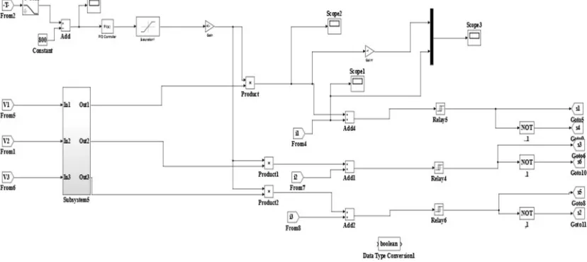
The wind energy generating system is connected to the grid having the nonlinear load. The bang-bang current controller for STATCOM is implemented in MATLAB/SIMULINK. The main SIMULINK diagram of the control schemes with STATCOM is shown in Fig.5.
The MATLAB/SIMULINK diagram of proposed Control-scheme of STATCOM shown below in Fig.6.
Fig.6: Simulation diagram for Control-scheme
The performance of the system was measured by switching STATCOM at a time t = 0.7s in the system. When the STATCOM controller is turned on without changing the other load state parameters, it starts to decrease for the aircraft search and for the harmonic current. The results of the source voltage, current, and charge currents are shown in Figure 7, Figure 8 and Figure 9. While the output of the current injection from STATCOM is shown in Figure 10. The supply voltage and current in the PCC are shown in Figure 11.
Fig.7: 3-phase source voltage
Fig.9: 3-phase load current
Fig.10: 3-phase injected current
Fig.11: Supply voltage and current at PCC
The DC link voltage regularizes the source current in the grid system, so the DC link voltage is maintained steady across the capacitor as shown in Fig.12 (a). The current through the dc-link capacitor indicating the charging and discharging operation shown in Fig. 12(b).
(b) Fig.12 (a).and (b)
It is observed that the source current in the power grid is affected by the influence of non-linear load and generator so that the purity of the waveform can be lost on both sides of the system. The output voltage of the inverter when operating STATCOM with load variation is shown in Figure 13. Dynamic loads affect the output of the inverter Voltage.
Fig.13: STATCOM output voltage
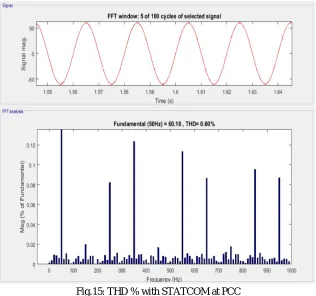
The current waveform before and after the STATCOM operation is analyzed. STATCOM is switched on at 0.7 s. The Fourier analysis of this waveform is shows and the THD of this source current at PCC without STATCOM is 11.90% as shown in Fig.14.
Improvements in power quality were observed at the common connection point when the controller closed at 0.7 seconds with STATCOM, the percentage of THD is 0.60% as shown in Fig.15 THD has been shown to improve significantly and within the normative norms.
Fig.15: THD % with STATCOM at PCC
The above tests with the proposed scheme have not only power quality enhancement feature but it also has maintained the capability to support the load with the energy storage through the batteries.
VII. CONCLUSION
The paper presents the STATCOM-based control scheme for power quality improvement of the grid-connected wind energy system with a non-linear load. Questions about electricity quality and its impact on consumers and power supply are presented. The operation of the control system designed for STATCOM-BESS in MATLAB / SIMULINK to maintain power quality is simulated. It is capable of releasing a harmonious portion of the charge current. It maintains the source current in phase and voltage and maintains the need for reactive power for the wind generator, and load at common coupling points in the grid system, thus allowing increased utilization factor of the transmission. , thus it gives an opportunity to enhance the utilization factor of a transmission line. The integration of wind energy system and STATCOM with BESS has shown outstanding performance. Therefore, the proposed scheme in the power grid system meets the energy quality standard in accordance with IEC standard 61400-21.
Table 2
Comparison of Non-Linear Unbalanced Load for without and with STATCOM
Parameters Without STATCOM With STATCOM
THD 11.90% 0.60%
Power factor Not unity unity
Source current Non-sinusoidal Sinusoidal
Load current Non-sinusoidal (unbalanced)
Sinusoidal (balanced)
[image:10.612.159.450.621.720.2]REFERENCES
[1] S. W. Mohod and M. V. Aware, "A STATCOM-Control Scheme for Grid Connected Wind Energy System for Power Quality Improvement," in IEEE Systems Journal, vol. 4, no. 3, pp. 346-352, Sept. 2010.
[2] V. Yuvaraj, E. P. Raj, A. Mowlidharan and L. Thirugnanamoorthy, "Power quality improvement for grid connected wind energy system using FACTS device," Proceedings of the Joint INDS'11 & ISTET'11, Klagenfurt, 2011, pp. 1-7.
[3] M. Muthusamy and C. S. Kumar, "New STATCOM control scheme for power quality improvement in wind farm," 2014 International Conference on Green Computing Communication and Electrical Engineering (ICGCCEE), Coimbatore, 2014, pp. 1-5.
[4] S. K. George and F. M. Chacko, "Comparison of different control strategies of STATCOM for power quality improvement of grid connected wind energy system," 2013 International Mutli-Conference on Automation, Computing, Communication, Control and Compressed Sensing (iMac4s), Kottayam, 2013, pp. 650-655.
[5] Rakhi Deshmukh, Rahul Rahangdale and M.K. Pradhan “A Power Quality Improvement By using STATCOM and Wind Turbine” International Journal of Engineering Trends and Technology (IJETT) – Volume 32 Number 6- February 2016.
[6] J. Manel, “ Power electronic system for grid integration of renewable energy source: A survey ,” IEEE Trans. Ind. Electron., vol. 53, no.4, pp. 1002-1014, 2006, Carrasco.
[7] C. Han et.al., “ STATCOM impact study on the integration of a large wind farm into a weak loop power system ,” IEEE Trans. Energy Conv., vol. 23, no. 1, pp. 226-232, 2008.
[8] R. S. Bhatia, S. P. Jain, D. K. Jain, and B. Singh, “Battery energy storage system for power conditioning of renewable energy sources,” in Proc. Int. Conf. Power Electron Drives System, vol.1, pp. 501–506, Jan.2006.
[9] A.Jeyamari and B. Prabakaran “Power Quality Improvement Of Grid Connected Wind Power System Using STATCOM” International Journal of Engineering Research & Technology (IJERT), Vol. 2 Issue 6, June – 2013.
[10] Sheeraz Kirmani and Brijesh Kumar “Power quality improvement by using STATCOM control scheme in wind energy generation interface to grid”. IOP Conf. Series: Earth and Environmental Science 114 (2018).
[11] Kumar, L Ashok & Naganathan, Archana & Vidhyapriya, R. (2015). “Power quality improvement of grid connected wind energy systems using STATCOM-battery energy storage system”. 10. 9872-9879.
[12] B.v.v. 1 kala bharathi, S.Dileep kumar varma “Power Quality Improvement for Grid Connected Wind Energy System Using Svc Light” International Journal of Engineering Research & Technology (IJERT) Vol. 1 Issue 6, August – 2012.
[13] Dr. S.M. Ali, B.K.Prusty, M.K.Dash and S. P. Mishra “Role of Facts Devices in Improving Power Quality in A Grid Connected Renewable Energy System” JERS/Vol. III/ Issue III/July-Sept, 2012.
[14] Woei-Luen Chen, Yung-Hsiang Lin, Hrong-Sheng Gau, Chia-Hung Yu “STATCOM controls for a self-excited induction generator feeding random loads” IEEE Transactions On Power Delivery, vol. 23, no. 4, October 2008. Fu. S. Pai and S.-I. Hung, “Design and operation of power converter for microturbine powered distributed generator with capacity expansion capability,” IEEE Trans. Energy Conv., vol. 3, no. 1, pp. 110–116, Mar. 2008.