[ 6
5 4]
THE JUMPING MECHANISM OF SALTICID SPIDERS
BY D. A. PARRY AND R. H. J. BROWN Zoological Laboratory, Cambridge
(Received 13 June 1959)
(With Plates 13 and 14)
INTRODUCTION
There are no extensor muscles at the 'hinge joints' (femur-patella and tibia-basitarsus joints) of the spider leg. Parry & Brown (1959) have recently produced evidence that at these joints extension is due to the haemocoelic blood pressure in the leg: we measured this pressure, established an empirical relation between pressure and torque at the hinge joints, and used this relation to show that the observed pressures are adequate to account for the torques developed by the living spider.
In this paper we consider whether a hydraulic mechanism is likely to account for the jump of the jumping spider Sitticus pubescens (Fabricius: Salticidae). First a description of the jump is given and it is shown to depend almost entirely on the sudden straightening of the fourth pair of legs. From photographs of the jump we estimate the mean acceleration during take-off and hence the propulsive force and the torques at the hinge joints. Finally we use the relation between torque and blood pressure already established for the house spider Tegenaria sp. (Parry & Brown, 1959) to obtain a rough estimate of the blood pressures which would be needed to account for the jump.
DESCRIPTION OF THE JUMP Method
The photographic equipment consists of a continuously-running camera synchro-nized with a British Thomson-Houston Type FA I discharge tube used as a multiple-flash light source (Brown & Popple, 1955). The spider is photographed while jumping across a gap of about 5 cm. from a narrow take-off platform to a wider landing platform. By idling the camera motor and then suddenly releasing the clutch when the spider is judged to be on the point of jumping, we were able to get a number of sequences of the jump taken at maximum camera speed—167 half-frames/sec. (6 msec, per half-frame) on 35 mm. film. In addition to these sequences we also took a number of multiple-image photographs of the complete jump, using a flash interval of 7 msec, and a ' black box' background. All this work was done at a temperature of about 20° C.
The jump
The jumping mechanism of salticid spiders 655
been determined. The jump of a mature male Sitticus pubescens is shown in PI. 13, and the following points will be noted: (a) The fourth legs are held in a plane parallel to the vertical sagittal plane of the animal and straighten to their full length during the jump chiefly owing to extension at the femur-patella hinge joint and to depression of the femur; (b) the third legs are held laterally and move through a small angle before losing contact with the ground; (c) the first and second legs are held off the ground and do not contribute to the jump.
The multiple-image photographs (PI. 14) show the use to which the drag-line silk is put during the jump. In PI. 14a the animal executes a rather flat trajectory, drawing out a silk thread behind it (visible in the first two images and also bridging the gap at the end of the jump). Tension in this thread probably accounts for the reversal, in mid-air, of the animal's initial counter-clockwise rotation (pitch). In PI. 146 there is a similar initial rotation, but here the tension in the thread appears to have suddenly increased so that not only is the rotation reversed but the animal drops almost vertically at the end of its jump. In PI. 14c the thread seems to have broken and the animal makes a complete somersault.
It must be emphasized that the description just given of the salticid jump applies to Sitticus pubescens alone and that other species may jump differently, althbugh we have no reason to believe that there are radical differences. For instance the zebra spider Salticus scenicus (Clerck) uses both the third and fourth pairs of legs when jumping, the third pair leaving the ground after the fourth pair. It is particularly
fortunate for our purposes that in the species we happened to choose for study the jump is almost entirely due to a single pair of legs: otherwise the torques at the joints could not have been resolved.
TORQUES AT THE LEG JOINTS
Method
Details of the method used in calculating the torques at the leg joints during the jump are given in the appendix. In principle the method is as follows. From a photographic sequence we measure the angle of take-off, the distance moved by the spider's body during take-off, and the velocity of take-off. Thus we obtain the mean acceleration and, knowing the spider's mass, the magnitude and direction of the force acting on the spider. Taking this force to be equally distributed between the feet of the fourth pair of legs, we then calculate the torques at the joints for each of the leg configurations shown in the film.
The principal assumptions made in this calculation are:
(a) The third pair of legs contribute a negligible amount to the jump (the first and second legs need not be considered because they are held off the ground). This assumption is supported by the fact that removal of the third pair of legs has little effect on the take-off velocity of the jump—see 'other measurements of take-off velocity' below.
656 D. A. PARRY AND R. H. J. BROWN
increased flash frequency and camera speed. This is one reason why our numerical results must be taken as approximate. They should, however, be adequate to show whether active extension is occurring at the hinge joints, and whether it would be reasonable to account for this extension in terms of blood pressure.
2 mm.
Text-fig. 1. Tracings of three jumps. The disposition of the fourth leg is shown as far as the trochanter-femur joint.
Results
The jumping mechanism of salticid spiders 657
but may change to a depression towards the end of the jump. Except when the legs are almost outstretched the torques at the hinge joints are considerably larger than those at the base of the leg, the latter always being relatively small.
PRESSURE IN THE LEG
We have shown (Parry & Brown, 1959) that under static conditions the following relation between torque (C) and pressure (P) holds good for the Tegenaria hinge
joint: C = k
exP,
where kg is a constant for any given joint angle. If C is measured in dyne-cm, and P is measured in dynes/cm.* then kg has the dimension cm.3 and is numerically equal to Av/A0 or the rate of change of joint volume with angle. It thus depends only on the geometry of the joint and for similar joints—such as the Tegenaria and salticid hinge joints—will vary with the cube of the linear dimension. Table 1 shows, for each hingejoint, first the values of kg for Tegenaria (Parry & Brown, 1959), and then the calculated values of kg for the two salticids used in our experiments, obtained by multiplying the Tegenaria values by the ratio of the cubes of the respective hinge lengths. The actual lengths of the hinges were as follows. Upper
joint: Tegenaria: 0-830 mm.; salticid A: 0-247 mm-> salticid B: 0-304 mm. Lower
joint: Tegenaria: o-6oo mm.; salticid A: 0-160 mm.; salticid B: 0-198 mm.
Table 1
Joint angle
Tegenaria Sitticus, spider A Sitticus, spider B
Tegenaria Sitticus, spider A Sitticus, spider B
40° 440 II 22
E
6o° 37o 10 18 — 8o° 100°U p p e r joint
320 8 16 310 8 IS
L o w e r joint
170 6 150 3 S I2O° 3OO 8 15 130 3 S 140° 200 8 14 130 3 5 1600
200 x io~
5
mm.1 = kg
120 x io~' mm.' 2
4
kg
We have used these calculated values of kg to estimate the pressures needed to produce the torques developed during the jump—the pressure in cm. Hg is shown in parentheses in Text-fig. 2 beside the corresponding torques. It will be noted that:
(a) Although the torques are about the same at the two hinge joints, the cor-responding pressures appear to be greater at the lower joint owing to its smaller size. In fact, unless viscosity effects are important, the pressure must be the same throughout the leg and the apparently lower pressure at the upper joint must therefore be due to flexor muscle tension.
0
0
p
>
13 oText-fig
. 2
. Fo
r legen
d
te
e p
. 659
660 D. A. PARRY AND R. H. J. BROWN
hinge lengths would produce an error of 25 % in the calculated pressures. In fact some of the pressures at the lower hinge joint are improbably high, but all lie within a factor of two and a half of the peak pressures actually measured in the leg of Tegenaria (Parry & Brown, 1959). Our results are therefore compatible with the idea that the hinge-joint torques are due to hydraulic pressure. It should be noted that, between similar animals of different size, the pressures will be similar because the force of a muscle is proportional to its cross-section—i.e. Force/Area (a pressure) is constant.
Direct evidence that the blood pressure increases during jumping is provided by the behaviour of the leg spines which, in many spiders, become erect when pressure is applied to the body or to an isolated leg. PI. 13 shows the spines erecting on the legs during the jump—this is clearly seen on the first and fourth legs and is also visible on the third legs (compare the first three sequences). The fact that erection is not limited to the jumping legs strongly supports the idea that the increase in pressure occurs throughout the prosoma.
OTHER MEASUREMENTS OF TAKE-OFF VELOCITY
Two other methods are available for measuring the take-off velocity and angle of take-off. These do not give the take-off distance and so the acceleration and force cannot be calculated; they do, however, provide an independent indication of the spiders' normal performance. These methods are:
(a) The spider is allowed to jump across a parallel beam of light so that its shadow falls on a sheet of graph paper. One observer notes the maximum height of the trajectory of the shadow while another observer notes the range and the height of the landing point above or below the take-off point. These measurements define the trajectory and enable the velocity of take-off and the angle of elevation to be calculated.
(b) From multiple-image photographs (e.g. PI. 14) the angle of take-off and the maximum height can be measured: these parameters determine the velocity.
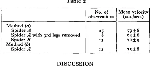
[image:7.451.95.356.475.591.2]Estimations of the take-off velocity obtained by these two methods are shown in Table 2.
Table 2
Method (a) Spider A
Spider A with 3rd legs removed Spider B
Method (6) Spider A
No. of observations
8 13
1 2
Mean velocity (cm./sec.)
79±8 64±6
76±9
75±8
DISCUSSION
The jumping mechanism of salticid spiders 661
torques at these joints are considerable. Perhaps the most significant evidence that extension at the hinge joints is due to hydraulic forces comes from the unexpected discovery that the leg spines become erect during the jump—a result of increased body pressure which can be demonstrated on many spiders. Calculation of the actual pressures at the joints needed to produce the estimated torques can only be very approximate. They do, however, fall within a factor of about two of the peak pressures actually measured in the Tegenaria leg (Parry & Brown, 1959).
Although we have thus produced evidence that the jump is due to hydraulic forces, we are still far from understanding the detailed mechanism involved. Some of the main points yet to be decided are:
(a) Which muscles control the blood pressure? We believe they are in the pro-soma—see Parry & Brown (1959) and also note that spine erection is not limited to the jumping legs.
(b) Do the muscles shorten during the jump; or do they do so before the jump begins, the work being stored as elastic energy?
(c) What pressure gradients occur within the leg due to the flow of blood into the expanding hinge joints?
We hope that further studies of larger spiders may throw more light on some of these questions.
The range of a projectile depends on the angle of projection and the square of
the initial ('take-off') velocity {R = sin 28 x (v2lg)} and for a given terminal
velocity is greatest when 6 = 45 °. Usually Sitticus pubescens takes off at an angle less than 45 ° and in most of our determinations of take-off velocity it landed on a vertical surface placed up to 7 cm. away. The greatest take-off velocity encountered
was 99 cm./sec., and if the angle had been 450 this would have produced a jump of
10 cm. provided there was no check from the drag-line. Energy considerations show that, other things being equal, range should be independent of size:
Range a v* (see above).
Work done by muscles === %mv2 (neglecting increase in potential energy
during take-off which is relatively small). _ . . work done by muscles
I nerefore range <x . . . . mass of spider
Temperature is likely to be one of the most important factors influencing the work done by a given amount of muscle. Buchthal, Weis-Foch & Rosenfalck (1957) found that the twitch work of locust flight muscle increased by a factor of |- for an increase in 12° C. (20-32°). Thus temperature could account for jumps of 20 cm. performed by a South American salticid at an air temperature of 30° (we are grateful to Dr H. W. Lissmann for these observations). It might also account for jumps of 25 cm. reported by Pickard-Cambridge (1879) for Attulus ('Attus') saltator which lives on sandhills and in similar unsheltered environments which may get very hot on a sunny day.
662 D. A. PARRY AND R. H. J. BROWN
to the contraction of muscles which, owing to the gearing provided by the anatomy of the leg, may work at close to their optimal mechanical efficiency. In a hydraulic system the work which the muscles can do in a single contraction depends on the compliance (relation between dimensional changes and pressure) of the animal's body and on the volume change occurring at the leg joints. It appears that muscles operating such a system do so at considerably less than their optimum efficiency. However salticid spiders are small, so that although their absolute range is poor the range measured in terms of the body length is considerable, and this often has the greater biological significance.
SUMMARY
1. Photographs of the jumping spider Sitticus pubescens (Salticidae) show that the jump is almost entirely due to the sudden straightening of the fourth pair of legs. Multiple-image photographs show the importance of a silk drag-line in controlling the jump.
2. The torques at the leg joints have been estimated. Extension torques occur at the two hinge joints although these lack extensor muscles.
3. The erection of leg spines at the moment of the jump provides direct evidence that hydraulic forces are involved in the jump. This view is supported by estimates of the pressures involved, which fall within a factor of about two of those previously measured in the legs of the spider Tegenaria.
We are greatly indebted to Dr K. E. Machin for his advice on the analysis of the fore es involved in the ump, and for reading the manuscript.
REFERENCES
BROWN, R. H. J. & POPPLE, J. A. (1955). Multiple flash photography. Med. Biol. Illuttr. 5, 33-8. BUCHTHAL, F., WEIS-FOCH, T. & ROSENFALCK, P. (1957). Twitch contractions of isolated flight
muscles of locusts. Acta physiol. stand. 39, 246-76.
PARRY, D. A. & BROWN, R. H. J. (:959). The hydraulic mechanism of the spider leg. J. Exp. Biol. 36, 423-33.
PICKARD-CAMBHIDGE, O. (1879). The Spiders of Dorset. Sherbome.
APPENDIX
This appendix shows in detail the method of calculating the torques at the joints of the salticid during a jump.
(a) Calculation of the force acting at the foot (see Text-fig. 3) Let:
Take-off velocity = v cm./sec. (measured on film). Take-off distance = s cm. (measured on film).
Mean acceleration = £(»2/i).
Mass of spider = mg.
Mean resultant force through centre of gravity ( = mass x acceleration) = vhn = p
The jumping mechanism of salticid spiders
From a resolution of forces:
COS 6
Ground reaction (Fg) =
tan A =
sin A mg cos d F—mg sin 6'
663
(la)
(16)
(b) Calculation of torques at the joints
In Text-fig. 4 let a, )3 and y define the configuration of the leg, and ^, /g and ^
be the lengths of the segments OP, PQ and QR respectively. Also let Clt Ct and
Cs be the magnitudes of the equal and opposite torques at the joints P, Q and R.
Text-fig. 4
Since the mass of a leg segment is small compared with that of the spider, it can be shown that changes of momentum and angular momentum can be neglected. Hence the sum of all the forces acting on a segment must be zero—i.e. the ground
reaction FQ acting at the foot O will produce equal and opposite forces Fg at P,
Q and R as shown (Text-fig. 4). Furthermore the sum of all the couples acting on a segment must also be zero. Thus:
(i) Segment OP (actually the two tarsal segments taken together) is acted upon
by the anti-clockwise couple Fgl^ sin a and the couple C1. Calling clockwise couples
positive: - i ^ s i n o c + C i = o.
(1)
Ca = sin a.
664 D. A. PARRY AND R. H. J. BROWN
(ii) Similarly segment PQ (actually tibia and patella taken together) is acted
upon by the anti-clockwise couple Fgl^ sin /? and the couples — Cx and C2, and
- ^ , 4 sin j S - Q + C, = o.
Using (1): C2 = ^ ( ^ sin a + ^ sin j8). (2)
(iii) Similarly segment QR (the femur) is acted upon by the clockwise couple Fgl% sin y and the couples — C2 and C3; and
FelaS\ny-Ci + C3 = o.
Using (2): Ca = 2 ? ^ gin a + i; sin 0 - 4 sin y). (3)
(c) A worked example
The following calculation applies to the jump illustrated in PI. 13: Take-off velocity (v) = 67 cm. /sec.
Take-off distance (5) = 0-44 cm.
Mean acceleration = 5,130 cm./sec.1.
Mass of spider = o-oi g.
Resultant force through centre of gravity (F) = 51*3 dynes.
Angle of take-off (0) = 120.
Ground reaction (Fg) = 55 dynes (27-5 dynes per leg).
A = io°.
Dimensions of leg segments: ^ = OT8 cm.; ^ = 0-22 cm.; ^ = 0-19 cm. Con-sidering the disposition of the leg at the moment of take-off (PI. 13, 2nd frame):
a = 760; j9 = 120; y = 580.
Hence from equations (1), (2) and (3):
Cx = 4-8 dyne-cm.; C2 = 6 T dyne-cm.; C3 = i*6 dyne-cm.
Similarly for the disposition of the leg shown in PI. 13, 3rd frame:
a = 66°; j8 = 120; y = 840.
.'.Cx = 4-5 dyne-cm.; C2 = 5*8 dyne-cm.; Cs = o-6 dyne-cm. Finally for the disposition of the leg shown in PL 13, 4th frame:
a = 2i°; j8 = 7° ; y = 200.
.'.C1= i-8 dyne-cm.; C2 = I T dyne-cm.; C8 = —0*7 dyne-cm.
A^ofe. The signs of Clt C2 and C8 in this worked example indicate the sense of
the couples acting at each joint on the distal segment.
EXPLANATION OF PLATES
PLATE 13
Sitticus pubescent jumping. Frame interval 6 msec Note the inflation of the articular membrane of
the femur-patella joint, and the erection of the leg spines.
PLATE 14
Sitticus pubescent jumping, taken by multiple-flash photography (flash interval "j\ msec.). In a the silk drag-line appears to be used to check counter-clockwise pitch; in 6 it is used to
JOURNAL OF EXPERIMENTAL BIOLOGY, 36, 4 PLATE 13
PARRY AND BROWN—THE JUMPING MECHANISM OF SALTICID SPIDERS
JOURNAL OF EXPERIMENTAL BIOLOGY, 36, 4 PLATE 14