Abstract—Two full-scope power plant simulators to train operators, one for a coal-fired power plant and one for a combined cycle power plant were integrated in a common simulation environment and coupled with an expert system and additional modules to evaluate the trainees in theoretical aspects and to evaluate their operative actions via process simulation. The rule-based approach to knowledge representation was selected, and a graphic editor was developed to build the training exercises, from the simulation scenario until their execution sequence and criteria of evaluation. The final simulation system includes training exercises preloaded with specific objectives for each one of the simulated processes, and it has been implanted in a portable computer for its transportation and installation in the power plants, so the operators can use this system to practice onsite without the supervision of an instructor.
Index Terms— Power plant simulator, operators training, expert system.
I. INTRODUCTION
A wide list of the main benefits of using a variety of training simulators is shown in [1], some of the most important are: the ability to train on malfunctions, transients and accidents; the reduction of risk to plant equipment and personnel; the ability to train personnel on actual plant events; a broader range of personnel receiving effective training; and individualized instruction or self-training being performed effectively on simulation devices designed with these capabilities in mind.
Since more than 25 years, the simulation department of the Mexican Electric Research Institute (IIE) has designed, developed and started-up all the power plant simulators required for the Mexican Federal Commission of Electricity (CFE) to train its operators of thermal, geothermal and combined cycle power plants. These simulators have different scopes according to the training demands of the CFE, therefore in their training centers, the CFE have classroom simulators, full-scope replica and no-replica simulators, and with the aim of improving the onsite training programs, the
Manuscript received Jun 29, 2010. This project was supported by the Mexican Federal Commission of Electricity.
José Tavira-Mondragón, Rogelio Martínez-Ramírez and Fernando Jiménez Fraustro are with the Simulation Department, Mexican Electric Research Institute, Cuernavaca, Mor., Mexico (phone: 52-777-362-3817; fax: 52-777-362-3811; e-mails: [email protected], [email protected], [email protected]).
Roni Orozco-Martínez and Rafael Cruz-Cruz are with the Ixtapantongo National Training Center for Operators, Federal Commission of Electricity (e-mails: [email protected], [email protected]).
CFE also has portable part task simulators. Currently, the training centre of the CFE with the bigger number of simulators is The Ixtapantongo National Training Centre (CENAC-I), which is devoted to train the operators of thermal power plants, the available simulators in this centre, which have been developed by the IIE [2-6] are:
• Two full-scope replica control board simulators, one for a 300 MW thermal power plant, and one for a 400 MW combined cycle power plant
• Five full-scope simulators with graphic operation interface for: a 300 MW thermal power plant, a 350 MW thermal power plant, a 350 MW coal fired power plant, a 150 MW gas turbine power plant, and a 450 MW combined cycle power plant.
• Two classroom simulators, one for a 300 MW thermal power plant, and one for a 350 MW thermal power plant
• Two partial-task portable simulators, one for turning and acceleration of the main turbine, and one for a 300 MW thermal power plant
The partial-task simulators are portables, so they are transported to the power plants, in this way, the operators can practice onsite, these simulators can be utilized with the assistance of an instructor or in a free-hands context, but in any case they do not have an automatic tutoring system or an evaluation system. On the other hand, the full-scope and classroom simulators are hosted in the CENAC-I facilities and require of an instructor to guide the training session. With these simulators, the CENAC-I trains the operation personnel of the thermal power plants of the CFE, the training programs include retraining strategies, safe operation under malfunctions and familiarization with power plant systems. Another important issue is that the partial-task simulators are based on Unix operating system, while the other simulators are based on personal computers with Windows XP operating system and with a very similar simulation environment.
Currently, full-scope simulators are recognized worldwide as the only realistic method to provide real time and hands-on training of operators [7], however, the inclusion of intelligent tutoring systems to train power plant operators has been a study matter to enhance the capabilities of a power plant simulator [8], or as an intent to optimize operators training [9].
This paper describes the main features of a portable simulation system to train and evaluate operators onsite, without an instructor guidance. This system utilizes CLIPS as expert system [10], and keeps its attributes of full-scope, detailed mathematical modeling and real-time functioning for each one of the two simulated processes (a 350 MW
Power Plants Simulators with an Expert System
to Train and Evaluate Operators
coal-fired power plant and a 450 MW combined cycle power plant). The software architecture and the most important aspects of the developed tools to design the training exercises are also shown; finally the results and conclusion achieved are presented.
II. THE POWER PLANT SIMULATORS
Because of the training demands onsite, the 350 MW Coal-Fired power plant Simulator (CFS) and the 450 MW Combined Cycle power plant Simulator (CCS) were selected among the available simulators at the CENAC-I. The CFS reproduces the behavior of a 350 MW dual fuel power plant, so it can operates with oil or coal as fuel, this unit has as main components: a forced circulation steam generator, a tandem compound turbogenerator, the feedwater system, and the auxiliary systems (e.g. lubrication oil, fuel, water services, electric grid, etc. ). On the other hand, the CCS reproduces the behavior of a 450 MW combined cycle power plant, this unit has as main components: two gas turbines, two Heat Recovery Steam Generators (HRSG), one tandem compound turbogenerator, the feedwater system, and the auxiliary systems (e.g. lubrication oil, fuel, water services, electric grid, etc. ). Due to these simulators are of the full-scope type, their mathematical models must be able to reproduce, in a dynamic way, the behavior of the power plant in any feasible operation, this means, any steady state from cold iron up to full-load generation, and transients states as a part of operation itself or because of malfunctions, therefore, the simulators have detailed mathematical modeling based on physical laws, and to customize the models, to the actual power plant used as reference, each one of the equipments (tanks, valves, pumps, fans, heat exchangers, etc.), are characterized with design information and operation data. In this kind of modeling, the governing equations are formed by a group of algebraic and first- order differential equations, as an example of this approach, the calculation of the flows and pressures related with the steam turbine and the energy variation inside of the HRSG elements are presented.
The calculation of the flow through the turbine stages is approximated by [3]:
m m m i
i p p
P m
m K
W 2/ ( 1)/
1
2 − +
−
=
ρ
(1)where m is the polytrophic coefficient, ρ is the steam density, K is the stage conductance and p is defined as:
1 ; ≥ −
−
= δ δ
i
P P P P p
o i i
δ is the stages number where the flow rate is being evaluated, and i and o denotes the input and output conditions.
In steady state, the continuity equation in any flow-node satisfies:
∑
Wi−∑
Wo=0where W are the flow rates. In a general approach, the application of equation (1) to all network flow-nodes yields a system of simultaneous nonlinear equations:
[
]
0, 1 =
−
=
∑
Wi∑
Wo k ndF (2)
This system is resolved by the Newton-Raphson method. The construction of the Jacobian matrix is made with the analytical or numerical first-order partial derivatives with respect to the flow-nodes pressures Pk.
In the case of the HRSG, a lumped parameter model is used, and additionally it is supposed a perfect mixing inside the boundaries of the control volume, in this way, the energy variation inside the tubes of each section of the HRSG is calculated by:
V Q h h W dt
dU i
ρ
+ −
= ( ) (3)
the heat flow rate transferred to the fluid is:
(
T
T
)
A
j
Q
f=
metal−
(4)where U is the fluid internal energy, h is the fluid enthalpy, V is the control volume, j is the heat transfer coefficient, A is the transfer area and T is de temperature. The equations (3) and (4) are parameterized and evaluated for each one of the sixteen sections of each one of the two HRSGs. The differential equations are resolved with Euler or Second Order Runge-Kutta methods.
Once all the governing equations had been developed and programmed, each one of the models were tested and validated in an independent way, and their corresponding step-size integration methods were defined. After that, they were inserted into a modular sequential solver according to their causality.
On the other hand, each one of the simulators has a distributed control simulated; these systems include manual, semi-automatic and automatic operation modes, according to the specified requirements of the simulated areas. In brief, the control algorithms are organized in basic components with a very specific function (PID, Set/Reset, Dead Band, Limiters, etc), and they are represented through a hierarchical components network. This network is stored as a diagram and a group of diagrams constitutes a module. These modules have their own solver according to the order of precedence of the modules.
III. HARDWARE AND SOFTWARE ARCHITECTURE Due to the simulation system will be continuously transported to power plants, a robust and portable computer platform was selected, for a safe and easy transportation. The computer selected is a personal computer with three integrated monitors (Fig. 1). This computer, based on Windows XP operating system, has a dual Xeon quad processor of 2.66GHz, 4 GB memory, one 160 GB hard disk and three LCD monitors.
The software architecture of the simulation system is shown in the Fig. 2, the CFS and the CCS used as base simulators for the new simulation system were adapted and integrated to this architecture. The description of the software modules is presented in the following paragraphs.
A. Simulator Modules
is presented. The control models and process mathematical models are discussed in section 2.
1) Real Time Executive
The real-time executive module coordinates all simulation functions and its main parts are: a) the mathematical model launcher; b) the manager module for interactive process diagrams; c) the manager module for the global area of mathematical models; d) the manager module for the instructor console; e) data base drivers.
2) Main Sequencer
It is in charge of sequencing, in real-time, all the functions which require a cycling execution, these are: mathematical models, control models and other additional functions like historical trends.
3) Operator Module
The operator module is in charge of the operator human machine interface (HMI) and manages the information flow with the executive system. The HMI consists of interactive process diagrams, which are Flash movies; the flash movies have static and dynamic parts. The static part is constituted by
a drawing of a particular flow diagram whereas the dynamic part is configured with graphic components stored in a library which are related to each one of the plant’s equipment, e.g., pumps, valves, motors, etc. These components have their own properties and they are established during the simulation.
4) Instructor Console Module
This interface is hidden to the trainee, but the instructors of the CENAC-I can access it during the stage of design, test and debug of the training exercises. This module consists of five parts: a) a main module for carrying out all the tasks related to the graphical interface of the instructor; b) a module for retrieving the static information of the simulation session, e.g., malfunctions, internal parameters, etc; c) a module for storing information in a data base using SQL; d) a module for dynamically updating the instructor console with the simulation information; e) a module for communicating the instructor console with the real-time executive.
B. Evaluation Console Modules
These modules integrate the software developed to train and evaluate the trainees.
1) Expert System
The expert system is based on the C Language Integrated Production System (CLIPS), which is a widely used tool to build expert system by government, industry and academia. The expert system is responsible of tracking the status of the simulation to determine the group of rules that should be fired. Due to its inference engine, and according to the configuration of the simulation exercise, the expert system is able to modify the simulation process, because it can insert malfunctions, modify values of selected process and control variables, and change the status of the simulation without the intervention of an instructor. The expert system is embedded within the real-time executive of the simulator. In order to interface the expert system with the main sequencer, external functions are added to the inference engine of the expert system.
2) Exercises Editor
This editor is a graphic tool to configure the training exercises in the simulation system. This configuration has two parts:
• Simulation scenario. In this part are defined aspects like: exercise objective, initial condition for the simulation (e.g. cold iron, full-load, etc), trend graphics, interactive process diagrams, process variables to evaluate the simulation, and questions for the theoretical evaluation
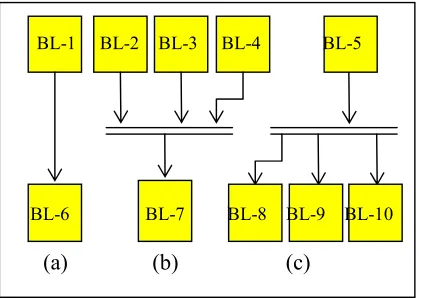
• Exercise sequence. This sequence is established through a graphical language, which is a data flow language where basic elements are blocks and lines, the blocks have a specific function, for instance, to send a message to the user or establish a waiting time for an action. Each block consists of a header and an action, in the header is the logical code to launch its action. The execution sequence of all the blocks, and the communication among them is carried out by means of lines, in this way, an active input line is the signal to start the block, and an active output line indicates the block has finished its function. Additionally, the blocks have another input line to abort the block operation. The connection types among the blocks are shown in Fig. 3, in this Figure, a sequential type (a) indicates that a lower block is not started until the upper block is finished; in the synchronized type (b), the lower block does not start until all the upper blocks are finished; in the parallel type (c), once the upper block
Real-Time Executive
Main Sequencer Control
Models
Math. Models
Operator Instructor
Console
Trainee Interface Theoretical
Evaluation
Evaluation Console
Expert System
Exercises Editor
Figure 1. Computer Platform
finishes, the inputs to all the lower blocks are activated; naturally, combinations of these connections are possible. The result of this edition is a directed acyclic graph and it is stored in XML format. Finally, with a specially developed translator, the XML file is transformed in a new file containing an ordered group of rules which are the base information for the expert system 3) Theoretical Evaluation
The conceptual support of the training exercises is supported by multimedia lessons, and a theoretical evaluation. The multimedia lessons consist of theoretical explanations related with the training exercise and they can be presented to the trainee through different multimedia formats. In the case of the theoretical evaluation, the questions related with the exercise objectives are captured in a database, and at the moment of the evaluation they are selected and displayed randomly. This module is also in charge of feedback to the trainee, when he makes mistakes in responding the questions.
4) Trainee Interface
This interface allows trainee to access the training exercises in the simulation system, and it is composed by three monitors, one of them has the trainee functions to control the simulation and a window to show the messages from the expert system. For the operation of the simulated process, the trainee has two monitors with interactive process diagrams, which have the same look and functioning like the diagrams of the base simulators, in this way, the trainees do not need to learn a new operation interface.
IV. KNOWLEDGE ACQUISITION AND REPRESENTATION A. Knowledge acquisition
The C Language Integrated Production System (CLIPS) is an inference engine initially developed to facilitate the representation of knowledge to model human expertise. CLIPS provides a cohesive tool for handling a wide variety of knowledge with support for three different programming paradigms: rule-based, object-oriented and procedural. Rule-based programming allows knowledge to be represented as heuristics, or "rules of thumb", which specify a set of actions to be performed for a given situation.
Object-oriented programming allows complex systems to be modeled as modular components, which can be easily reused to model other systems or to create new components. In the procedural approach, CLIPS can be called from a procedural language, perform its function, and then return control back to the calling program. Likewise, procedural code can be defined as external functions and called from CLIPS. When the external code completes execution, control returns to CLIPS [10].
Knowledge acquisition is built by carrying out predefined simulation exercises with the “Instructor Console” mode of the simulation system; these tests are derived of available training procedures for the simulators and they are performed by qualified instructors of the CENAC-I. The training procedures are the same utilized during the simulation sessions guided by an instructor in the replica simulators of the CENAC-I, therefore, they include all the operation actions required from the trainee, and this helps to build a very complete knowledge base. These procedures include normal operation (startup, normalization and shutdown operations, for each one of the power plant systems); and abnormal operations (predefined malfunctions, like pumps trips, pipe breaks, etc). In this way, with the record of the required operation actions, the results observed and the instructor (expert) experience, it is obtained all the necessary information for the expert systems.
B. Knowledge representation
According to the design specifications of the evaluation system, and the knowledge acquisition method, the rule-based approach to represent the knowledge was selected. This approach is also called IF-THEN rules. Some of the benefits of IF-THEN rules are their modularity, and that each one defines a relatively small and independent piece of knowledge. New rules can be added and old ones deleted usually independently of other rules. With the aim of avoiding resolution conflict, the rules must have a predefined order. The exercises editor is a graphic tool where the instructor of the CENAC-I builds the training exercises for the simulation system. These editor contains a group of blocks where each block represents a rule (or a group of rules), and each block is customized by its characteristic parameters. The available blocks in the current version of the editor are:
• Malfunction. It inserts a malfunction (e.g. pump trip, fouling in heat exchangers, etc).
• Local Action. It modifies a local action (e.g. local valves position).
• External Parameter. It modifies an external parameter (e.g. ambient temperature).
• Cancel Malfunction. It removes an active malfunction.
• Snapshoot. It takes a snapshot of the simulator state, so the user can return to this point in any moment.
• Message. It sends a message to the user.
• Conditional Message. It sends a message to the user when a specified condition is satisfied (e.g. when a temperature reaches an expected value).
• Timer. It establishes a time period for the trainee carries out an operative action.
[image:4.612.73.285.541.690.2]• True/False Question. It asks a true/false question to the user.
Figure 3. Connection Types
(a) (b) (c)
BL-1 BL-2 BL-3 BL-4 BL-5Figure 5. Implementation of an Exercise
• Multiple Choice Question. It asks a multiple option question to the user
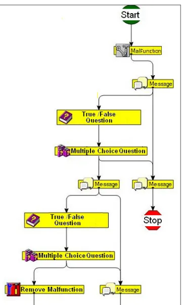
Fig. 4 is an example of a simulation exercise.
V. IMPLEMENTATION AND RESULTS
The purpose of the developed system (simulator-expert system) is to provide a standalone application where operative personnel of the power plants can practice and evaluate themselves without the supervision of an instructor; this practice will be a complement of the regular training courses carried out at the CENAC-I, due to this, the training exercises are designed with a very specific objective and a duration among 20 and 60 minutes.
Fig. 5 shows in a simple way the proposed approach to develop and implement the training exercises. The design stage of the exercise is carried out by a qualified instructor of the CENAC-I. In this phase the instructor, based on implanted operation procedures, develops a training exercise with a specific objective, for instance, boiler warming from ambient temperature up to 120OC. The process of warming the boiler from ambient temperature up to nominal conditions (540 OC) requires at least of 6 hours, but instead of having very long exercises, which can discourage or bore to the trainees, the proposed exercise has a duration of 30 minutes, and the goal is to train and evaluate to the trainee in specific operative actions related with the startup of the oil system and the initial stage of boiler warming.
As a part of the simulation scenario, the instructor defines the initial condition on the simulation system, creates the questions for the theoretical evaluation, assigns the corresponding multimedia material for the theoretical lessons, and selects the process variables for the simulation evaluation, for each one of these variables, the instructor defines a weight over the final grade, and also defines a time penalization in the case of exceeding the expected time to carry out the exercise. Finally with the exercises editor, the instructor “transforms” its operation procedure in a group of rules to guide/track the trainee operation supported by the expert system
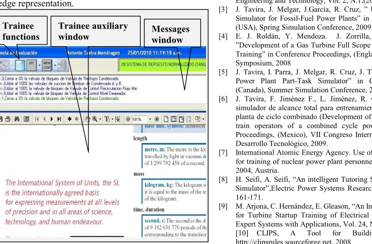
During a training session with the simulation system, the trainee has a graphical interface to perform by himself his practice. Fig. 6 shows a partial view of this interface, its main parts are:
• Trainee functions. These are the functions available for the trainee during a simulation session, and they are: 1) Selecting the simulator and the training exercise; 2) Run or stop the simulation; 3) Selecting snapshots; 4) Reloading the interactive process diagrams; 5) Displaying theoretical information related with the exercise scope, and application of the theoretical evaluation: 6) Selecting a new user.
• Trainee auxiliary window. This window displays the theoretical information of the exercise or it can be utilized to display a trend graphic or an interactive process diagram.
• Messages window. This window shows to trainee all the processed information by the expert system, for instance, if it is required a trainee action, the expert system displays a message, if the trainee carries out the right action, the message changes of color; if the trainee does not carry out the action, the expert system verifies the timer specified for the action, and it sends a warning message to continue the simulation or abort and initiate again the practice. All these options are fully configurable in the exercises editor. When some of the
Instructor of the Training Center
1 2 3 Trainee
Scenario
Exercise Sequence
Expert System
Theoretical Material
CFS / CCS
[image:5.612.100.280.415.717.2]User Interface
Figure 6. Partial view of the trainee interface criteria specified for finishing the exercise are achieved, the simulation system calculates the grade and shows the result to the trainee; after that, the simulation system is ready to start the execution of a new exercise.
The results of each one of the simulation exercises are stored in a database and they are available for the consult of the instructors of the CENAC-I. The main results stored are: trainee identification; grades of the theoretical test and of the simulation practice; total elapsed time.
Currently have been developed and tested two exercises for each one of the power plant simulated. For the coal-fired power plant simulator, the exercises are: boiler warming from ambient temperature up to 120OC, and malfunction detection of regenerative air heaters. In the case of the combined cycle power plant simulator, the exercises are: startup of feed water system, and steam turbine synchronization.
VI. CONCLUSIONS
With the aim of having a portable simulator, in which power plant operators can practice onsite, without assistance of an instructor, was developed a simulation system which includes an expert system, a 350MW coal-fired power plant simulator and a 450 MW combined cycle power plant simulator. These simulators were integrated in a common simulation environment, and they kept their detailed mathematical modeling, their full-scope and real-time features, and provide a suitable human machine interface to train operators of modern power plants, like the original simulators versions, which are installed in a training operators center of the CFE. Over this simulation environment were implanted an expert system and a group of functions to train and evaluate the trainees in theoretical and practical aspects of the simulated process. Due to the nature of the knowledge acquisition process, the ruled-based approach was selected to knowledge representation.
To create the simulations exercises for the trainee, a graphic editor was developed to design and implant in the simulator such exercises, thanks to this editor, the tasks related with coding of rules was replaced by a process of selecting, dragging and customizing the required blocks, which simplifies enormously the creation of exercises.
Each one of the simulation exercises can include: theoretical material to study; evaluation of theoretical concepts; guide and supervision, via an expert system, of the Trainee operation actions over the simulated process, and its corresponding evaluation. All these options are fully configurable from the exercises editor. The final objective of these simulation exercises is to provide to operators on site with a tool to practice specific operation actions, as a complement of the regular training programs which they carry out at the CENAC-I.
The whole system has been validated with the development and test of four simulation exercises for normal operation and malfunctions, and it is expected the simulation system is sent to the power plants once a complete group of exercises is developed, according to the current training requirements of the CFE.
ACKNOWLEDGMENT
The authors would like to thank all the personnel of the IIE and CENAC-I who participated in the project development. The simulation environment is proprietary software of the IIE, and it was customized to the particular requirements of this project.
REFERENCES
[1] International Atomic Energy Agency, Selection, specification, design and use of various nuclear power plant training simulators, IAEA-TECDOC-995, 1998, Austria
[2] J. Tavira, L. Jiménez, and G. Romero, “A Simulator for Training Operators of Fossil-Fuel Power Plants with an HMI Based on a Multi-Window System”. International Journal of Computer Aided Engineering and Technology, Vol. 2, N.1,(2010) 30-40.
[3] J. Tavira, J. Melgar, J.García, R. Cruz, ” Upgrade of a Full-Scope Simulator for Fossil-Fuel Power Plants” in Conference Proceedings, (USA), Spring Simulation Conference, 2009.
[4] E. J. Roldán, Y. Mendoza. J. Zorrilla, M. Cardoso, R. Cruz, ”Development of a Gas Turbine Full Scope Simulator for Operator’s Training” in Conference Proceedings, (England), European Modeling Symposium, 2008
[5] J. Tavira, I. Parra, J. Melgar, R. Cruz, J. Téllez” A 300 MW Fossil Power Plant Part-Task Simulator” in Conference Proceedings, (Canada), Summer Simulation Conference, 2006.
[6] J. Tavira, F. Jiménez F., L. Jiménez, R. Cruz, “Desarrollo de un simulador de alcance total para entrenamiento de operadores de una planta de ciclo combinado (Development of a full-scope simulator to train operators of a combined cycle power plant)”, Conference Proceedings, (Mexico), VII Congreso Internacional en Innovación y Desarrollo Tecnológico, 2009.
[7] International Atomic Energy Agency. Use of control room simulators for training of nuclear power plant personnel, IAEA-TECDOC-1411, 2004, Austria.
[8] H. Seifi, A. Seifi, “An intelligent Tutoring System for a Power Plant Simulator”,Electric Power Systems Research, Vol. 62, N. 3, (2002) 161-171.
[9] M. Arjona, C. Hernández, E. Gleason, “An Intelligent Tutoring System for Turbine Startup Training of Electrical Power Plant Operators”. Expert Systems with Applications, Vol. 24, N.1, (2003) 95-101. [10] CLIPS, A Tool for Building Expert Systems, http://clipsrules.sourceforge.net, 2008
Messages window Trainee
functions