Design and Construction of RF Remote Control
Based on PIC Microcontroller for Air
Conditioner
Theint Theint Soe
Department of Electronic Engineering, Technological University, Kyaing Tong, Myanmar
Abstract: This paper presents how to construct low cost RF remote control. RF transmitter (KST-TX01) and RF receiver (KST-RX706) are used in this system. In this system, PIC microcontroller 16F877 is selected to control home appliance, control card for air conditioner or virtually anything. Having the ability to control various appliances inside or outside wirelessly is a huge convenience, and can make life much easier and fun. This paper is also considered to get more cost effective. Chosen mode conditions mostly for air conditioner, auto mode, cool mode and fan mode to control card in air conditioner can be chosen from RF remote control device. In this system, fan mode of control card from receiver section is only proposed. Designed mode results are displayed on LCD. The designed wireless RF remote signal is implemented by using microcontroller technology.
Keywords: Microcontroller, Air Conditioner Control Card, RF Remote Control, Liquid Crystal Display (LCD), Cost Effective
I. INTRODUCTION
Nowadays, wireless RF modules are widely used in many applications. The target of the paper is to gain intelligent device control and secure environment working conditions by interfacing various sensors and devices to the DIP40 PIC 16F877 microcontroller and RF modules with the PIC controller for transmission data. The RF module, as the name suggests, operates at Radio Frequency. The corresponding frequency range varies between 30 kHz & 300 GHz. In this RF system, the digital data is represented as variations in the amplitude of carrier wave. This kind of modulation is known as Amplitude Shift Keying (ASK). Transmission through RF is better than IR (infrared) because of many reasons. Firstly, signals through RF can travel through larger distances making it suitable for long range applications. Also, while IR mostly operates in line-of-sight mode, RF signals can travel even when there is an obstruction between transmitter and receiver. Next, RF transmission is more strong and reliable than IR transmission. RF communication uses a specific frequency unlike IR signals which are affected by other IR emitting sources.
II. HARDWARECOMPONENTSOFSYSTEMDESIGN
A. Microcontroller
A microcontroller is a self-contained system with peripherals, memory and a processor that can be used as an embedded system. Most programmable microcontrollers that are used today are embedded in other consumer products or machinery including phones, peripherals, automobiles and household appliances for computer systems. Due to that, another name for a microcontroller is "embedded controller." Some embedded systems are more sophisticated, while others have minimal requirements for memory and programming length and a low software complexity. Input and output devices include solenoids, LCD displays, relays, switches and sensors for data like humidity, temperature or light level, amongst others. Programmable microcontrollers contain general purpose input/output pins. The number of these pins varies depending on the microcontroller. They can be configured to an input or an output state by software [1].
B. PIC 16F877 Microcontroller
This system can be designed with the use of PIC16F887 microcontroller because it is compatible in this system. Various pin functions cannot be used simultaneously, but can be changed at any point during operation. The advantages of PIC16F887 are program memory size, EEPROM data memory size, number of timers, user RAM size and A/D conversion. PIC is used as the
main control unit in this system [2]. Here, the microcontroller will access decision to drive the particular load.
C. RF Module
RF transmitter module (KST-TX01) and RF receiver module (KST-TX706) are displayed in Figure 3.2 in the following. This RF module comprises of an RF Transmitter and an RF Receiver. Unlike infrared (IR) remotes, which are the most common, Radio Frequency (RF) remote controls are easier to use because they do not require line of sight [3]. This RF module comprises of an RF Transmitter and an RF Receiver. The transmitter/receiver (Tx/Rx) pair operates at a frequency of 434 MHz. An RF transmitter receives serial data and transmits it wirelessly through RF through its antenna connected at pin4. The transmission occurs at the rate of 1Kbps - 10Kbps.The transmitted data is received by an RF receiver operating at the same frequency as that of the transmitter. This RF module is shown in Fig. 1.
Fig. 1 RF Transmitter Module and RF Receiver Module [4]
D. Wide Range of RF Applications.
The RF Modules are used for wireless transfer data. This makes them most suitable for remote control applications. The RF module, as the name suggests, operates at Radio Frequency. The corresponding frequency range varies between 30 kHz & 300 GHz. In this RF system, the digital data is represented as variations in the amplitude of carrier wave. This kind of modulation is known as Amplitude Shift Keying (ASK). Transmission through RF is better than IR (infrared) because of many reasons. Firstly, signals through RF can travel through larger distances making it suitable for long range applications. Also, while IR mostly operates in line-of-sight mode, RF signals can travel even when there is an obstruction between transmitter & receiver. Next, RF transmission is more strong and reliable than IR transmission. RF communication uses a specific frequency unlike IR signals which are affected by other IR emitting sources [5].
E. RF Transmitter (KST-TX01) Pin Description
In present system, air conditioner remote control is designed and constructed. The RF transmitter (KST-TX01) is used for transmitting data between two remotely located PIC microcontrollers. There are four pins in the RF transmitter (KST-TX01). pin description of the RF transmitter is stated in Table 1.
TABLE 1
PIN DESCRIPTION OF THE RF TRANSMITTER [6]
Pin No. Function Name
1 Antenna Output Pin ANT
2 Ground (0V) Ground
3 Serial data input pin Data
4 Supply voltage, 5V Vcc
F. How to Interface KST-TX01 and KST-RX706 to Microcontroller
[image:2.612.102.506.515.585.2]5V so how defined the logic 0 will it just 0 v or another voltage state except the 5V and as example in RS-232 serial protocol the logic 1 is from -3V to -10V and the logic 0 from +3V to +10V as it is so what will be the logic 0 voltage value on the receiver.
G. RF Receiver (KST-TX706)
[image:3.612.106.506.184.256.2]The RF receiver (KST-RX706) is utilized for receiving data between two remotely located PIC microcontrollers. There are four pins in the RF receiver (KST-TX706). Pin description of the RF receiver is mentioned in Table 1.
TABLE 2
PIN DESCRIPTION OF THE RF RECEIVER [10]
Pin No. Function Name
1 Ground (0V) Ground
2 Serial data input pin Data
3 Serial data input pin Data
4 Supply voltage, 5V Vcc
III.PROPOSEDSYSTEMFORSOFTWAREPART
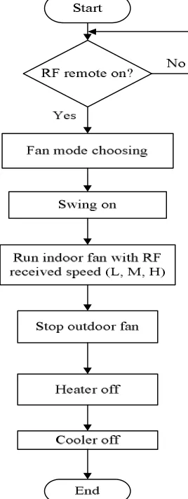
The operation of RF remote operation with microcontroller is written in embedded C programming language. In this system, three modes by selecting switches from RF remote control are considered. Although three mode conditions can be selected in this paper, only fan mode is tested. In fan mode condition, only the swing and indoor fan depending on the received speed from RF remote will operate but other operations will not work. The speed of the indoor fan can be selected by the conditions of low, medium and high from the switches of the RF remote control. The software is started with the initialization of the RF remote controller and is depicted in Fig. 2.
[image:3.612.244.378.355.711.2]IV. PROPOSEDSYSTEMFORHARDWAREPART
[image:4.612.84.528.113.281.2]The proposed block system illustrated in Fig. 3 comprises of two sections. The system block diagram is made up of the following block items. The RF Transmitter and RF Receiver with control card for air conditioner are presented in this system.
Fig. 3 Block Diagram of the Transmitter and Receiver Sections
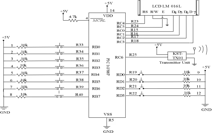
A. RF Remote Transmitter Circuit
The RF transmitter circuit schematic diagram where PIC16F877 microcontroller is used. In the circuit there are twelve (12) pushbuttons in following image Fig. 4 as shown, each pushbutton sends a different RF signal code via an RF transmitter. PIC16F877 internal oscillator is used (8MHz) and MCLR is disabled. In RF remote section, consists of a ASK transmitter. If an address in the remote section is set the same address, it will be required in the receiver section. So, always set same address in transmitter and receiver. The transmitted data is received by an RF receiver operating at the same frequency as that of the transmitter. Transmission through RF is better than IR (infrared) because RF can travel through larger distances making it suitable for long range applications. Next, RF transmission is more strong and reliable than IR transmission. Unlike infrared (IR) remotes, which are the most common, Radio Frequency (RF) remote controls are easier to use because they do not require line of sight.
Fig. 4 Circuit Diagram of RF Remote with Microcontroller
[image:4.612.128.494.431.661.2]Fig. 5 Twelve Switches of Wireless RF Remote Control
B. RF Remote Receiver Circuit and its Advantages of RF Remote Control
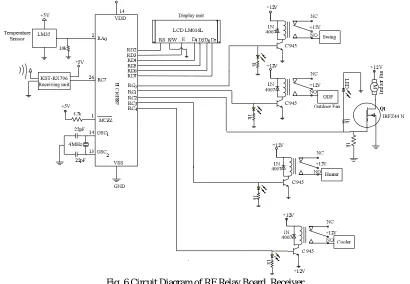
RF remote control provides long range of up to 200m / 650ft and can find many uses for controlling different devices, and it works even through the walls. Lights, fans, air conditioning system, computer, printer, amplifier, robots, garage door, security systems, motor-driven curtains, motorized window blinds, door locks, sprinklers, motorized projection screens and anything can be controlled. The control card in receiver section consists of four relays and one MOSFET IRFZ44N for the connection of output loads. The four relays with 5 V that cannot be controlled by the microcontroller directly are used. MOSFET IRFZ44N is used as a switch to drive the loads in receiver section. The load, brushless fan is used for indoor fan speed. In this system, Pin 2 of PORTC is connected to drive the indoor fan motor. The next pins pair is used for heating fan speed (the heater) and cooling fan speed (the cooler) connected with PINRC1 and PINRC2. The circuit diagram of RF relay board, receiver have been mentioned to each condition such as mode selections by the RF remote control illustrated in Fig. 6.
Fig. 6 Circuit Diagram of RF Relay Board, Receiver
C. Relay Board Construction
[image:5.612.106.516.366.650.2]Fig.7 RF Relay Board Construction
[image:6.612.173.438.379.454.2]In the following circuit construction, RF remote control which is suitable for this control card consists of twelve push switches, LCD display and RF transmitter. To achieve an easy transaction between two PIC16F887 microcontrollers, the following circuit uses inexpensive When the simulation runs, the LCD will be displayed the message " MODE: F, OF: N, IF: H, SWING:N , TEMP: NC" as shown in Fig. 8. PIC16F887 microcontroller is programmed to transmit its ADC data (RA0/AN0 channel) serially using its built-in USART hardware at 9600 baud with no parity and 8-bit data stream. The PIC’s USART transmitter (TX) pin feeds the data into the data pin of the KST-TX01 which transmits it using 433 MHz ASK RF signal. On the receiving end the KST-RX706 module receives the data and its output is connected to the PIC’s USART input pin. The second PIC is programmed to read its USART receiver (RX) pin. On both ends, two LCD displays are also connected which show the transmitted and received bytes. Since RS-232 communications typically allow 8-bit data, the 8-bit A/D conversion is used here for simplicity, instead of the more common 10-bit ADC. RF sensor module receives the RF pulses sent from remote and converts it to corresponding electric pulses. The control output signal is given to driver circuit received by the RF remote control unit and is displayed on LCD of RF remote. Hardware construction of the RF remote system with microcontroller PIC 16F877 is depicted in Fig. 9
Fig. 8 LCD Display for Fan Mode of the RF Remote Control
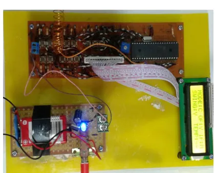
Fig. 9. Construction Diagram for RF Remote Control with Microcontroller
V. CONCLUSIONS
[image:6.612.205.415.471.640.2]this paper is partially fulfilled for air conditioning system. The used RF module in this paper is cheap and easy to use with any microcontroller. But their whole system was not cost effective a little. In this system, a remote control system which utilizes the radio frequency technology is developed.
VI.ACKNOWLEDGMENT
The author wishes to express her extremely grateful to her beloved parents and all of her family members. The author wishes to express her deep gratitude to all teachers who taught and supported her completion. The author is very thankful to Dr. Kyaw Thar Tun, Principal, Technological University (Kyaing Tong), for his kind encouragement The author is also thankful to my friend, Dr. Aye Aye (Technological University, Bamaw) who encourages me several times to write paper.
REFERENCES
[1] Anonymous: GDM 1602A (LCD-II), (2006), http://www.chipdocs.com/ pndecoder/datasheets/HIT/HD44780U.html [2] Anonymous: PIC16F8XX Data Sheet, Microchip Technology (2003).
[3] http://electronics-diy.com/infrared-remote-control-with-microcontroller. [4] A. Building an RF Remote Control System for Control, (1999).
[5] Islam, M.S. Multimedia Univ., Cyberjaya; Zaman Sarker, M.S.; Ahmed Rafi, K.A.; Othman, Development of Fuzzy Logic Controller Algorithm for Air Conditioning System- published in Semiconductor Electronics, 2006. ICSE 06, IEEE International Conference on date Oct. 29 (2006).
[6] http://gadgetronicx.com/wp-content/uploads/2014/01/RF-BASED-REMOTE-CONTROL.jpg [7] https://circuitdigest.com/microcontroller-projects/ir-remote-controlled-home-automation-using-pic [8] https://www.engineersgarage.com/electronic-components/rf-module-transmitter-receiver
![Fig. 1 RF Transmitter Module and RF Receiver Module [4]](https://thumb-us.123doks.com/thumbv2/123dok_us/1254897.652678/2.612.102.506.515.585/fig-rf-transmitter-module-rf-receiver-module.webp)