Abstract— Most of network simulators only support the store & forward mode that performs relay process for the received packet after all bits of a packet are received. In this paper, to resolve this problem of existing network simulators, we propose the method that can precisely model and simulate the cut-through mode of a relay communication on a computer- based network simulator.
Particularly, to model relay process of a cut-through mode for a real packet, we suggest and utilize two types of packets such as the Zero packet and the Copy packet. These make the proposed technique model accurately the transfer delay of a real packet in a cut-through relay, the start time of the state that the network after relay is busy, and the physical characteristic that a real packet experiences. Furthermore, the proposed method is used to develop the simulation model of the FM radio that can process a cut-through relay. Finally, based on the developed FM radio model, we have tested and verified the performance of the proposed method.
Index Terms— cut-through relay network, modeling and simulation, FM Radio, NetSPIN
I. INTRODUCTION
N general, the existing network simulator has worked to perform the relay processing for the received packet after all bits of a packet are received. In this case, the packet transmission procedure of the communication device that processes the relay communication of a store-and-forward mode is able to be simulated precisely.
However, the packet transmission procedure of the communication device that processes the relay communication of a cut-through mode is not able to be simulated precisely. It is because a cut-through mode has to perform a relay process in the state that all bits of a packet are not received [1].
Several problems may be caused due to imperfect modeling for the packet transmission procedure of the communication device that processes a cut-through relay.
Manuscript received July 26, 2011; revised August 16, 2011. This work was supported in the NetSPIN project by the Agency for Defense Development.
S. H. SHIM is with the 2nd R&D Institute - 1, Agency for Defense
Development, Seoul, Republic of KOREA (corresponding author to provide phone: +82-2-3400-2655; e-mail: ssheun@ hanmail.net).
S. I. LEE is with the 2nd R&D Institute - 1, Agency for Defense
Development, Seoul, Republic of KOREA (e-mail: happyjoy99@ paran.com).
B. I. CHO is with the 2nd R&D Institute - 1, Agency for Defense
Development, Seoul, Republic of KOREA (e-mail: [email protected]).
First, the transfer delay of packets in a cut-through relay process is not figured out accurately. Second, the start time for the busy state of the network after relay is not reflected precisely. Finally, physical characteristics (bit error rate, signal power, noise power, and etc.) that a packet experiences in the network before relay are not reflected on the received packet that is transmitted from the network after relay.
To resolve these problems, we propose the method that can precisely model and simulate the packet transmission procedure of communication devices that perform the relay communication of a cut-through mode on a network simulator.
In Section II, the proposed method for modeling of cut-through relay is described. In Section III, the proposed method is applied to develop the model of the FM radio that processes a cut-through relay. In Section IV, the performance test for the suggested method is conducted. Finally, its results are evaluated.
II. MODELING TECHNIQUE OF A CUT-THROUGH RELAY
A. Problem analysis
If a network simulator is not able to model the packet transmission procedure of the communication device that processes the relay communication of a cut-through mode, following problems will be brought about.
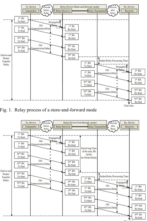
First, the transfer delay of a packet in a cut-through relay process is not assessed accurately. In most of network simulators using a store-and-forward mode, because a packet is transmitted to the network after relay only when a relay device receives all n bits of it from the network before relay, the end-to-end packet transfer delay De-t-e between a
transmitter and a receiver is calculated as in (1), refer to Fig. 1. n is the number of bits in a packet, and its range is 1 to N.
_
_ _
_
_
e t e
D Tx del of N bits in the network before relay
D p in the network before relay T rp
Tx del of N bits in the network after relay D p in the network after rel
− − =
+ +
+
+ ay
(1)
In (1), Tx_del is the transmission delay of a packet, D_p is the propagation delay of a packet, and T_rp is the relay processing time of a packet. In this paper, the unit of time is the second.
However, shown in Fig. 2, for a cut-through relay transmission, the end-to-end packet transfer delay De-t-e
between a transmitter and a receiver is calculated as in (2).
Precise Modeling & Simulation
of the Cut-through Relay Process
on the Network Simulator
Sangheun SHIM, Sangil LEE, and Byoungin CHO
_
_ _
_
_
e t e
D Tx del of k bits in the network before relay
D p in the network before relay T rp
Tx del of N bits in the network after relay D p in the network after rel
− − =
+ +
+
+ ay
[image:2.595.47.294.106.478.2](2)
Fig. 1. Relay process of a store-and-forward mode
Fig. 2. Relay process of a cut-through mode
Second, the start time for the busy state of the network after relay Tbusy is not modeled precisely. A packet
transmission has to be performed to make a network be a busy state. A cut-through relay has to transmit a packet to the network after relay using some k bits of it in the state that all n bits of it are not received from the network before relay.
However, because a general network simulator processes relay of a packet after receiving it perfectly, the network after relay is able to be a busy state when a relay receiver ends to receive a packet and the packet relay processing time elapses. In this case, the start time for the busy state of the network after relay Tbusy is calculated as in (3).
_
_ _
busy
T Tx del of N bits in the network before relay
D p in the network before relay T rp
=
+ + (3)
In case of the cut-through relay, equation (3) is different from the situation of the real network that the network after relay becomes a busy state at the time as in (4).
_
_ _
busy
T Tx del of k bits in the network before relay
D p in the network before relay T rp
=
+ + (4)
Finally, physical characteristics that a packet experiences in the network before relay are not reflected on the received packet that is transmitted from the network after relay.
General network simulators model that a transmitter starts to send a packet in the state that there are not bit errors in it. Therefore, when a relay transmitter sends a packet to the network after relay, the simulator considers that all bit errors of a packet produced in the network before relay have restored.
However, in reality, the cut-through relay device does not restore bit errors of a packet and transmits it to the network after relay. Therefore, a network simulator has to store the number of bit errors of a packet produced in the network before relay, and use it to judge whether the simulated model of a receiver is able to restore a packet or not.
B. Proposed methods
In this paper, we suggest the modeling technique for the relay communication procedure of a cut-through mode in a network simulator using following two methods. Related to these, Fig. 3 shows the process flow of modeling for the relay procedure of a cut-through mode.
Method 1
To model the relay procedure of a cut-through mode for a real packet, we suggest and use two types of packets such as the Zero packet and the Copy packet.
In case of modeling the packet in a network simulator, its length is independent of the amount of its information. However, the length of a packet is related to physical characteristics of a transmitted packet due to noise effects, fading effects, and etc. Especially, because each bit of a zero length packet does not have energy, it is able to be modeled to transfer between a transmitter and a receiver without experiencing a physical phenomenon. The propagation delay of a zero length packet is reflected on modeling, but the transmission delay of it is zero. And, the modeled transmission path and path loss of it are equal to those of a real packet.
To model the relay procedure of a cut-through mode, a real packet is modeled two types of packets. One is the Zero packet that its length is 0, and its information is equal to it of a real packet. The other is the Copy packet that has the length and the information equal to those of a real packet.
The Zero packet is transmitted along the path of a real packet, and experiences the path loss equal to it. However, because the Zero packet is received after a propagation delay from the start time of transmission, the simulated model of the relay communication device of a cut-through mode provides the information for relay transmission to the network after relay timely.
In other words, using the model of the Zero packet that has the information to restore data of a real packet, but does not have a transmission delay in a transmission process, the proposed method makes the simulated model of a relay communication device transmit the Copy packet made from the Zero packet to the network after relay while receiving a real packet.
makes a network simulator calculate physical characteristic values that reflect the physical phenomenon produced to a real packet.
In other words, because the Copy packet is modeled to get the same length and information of a real packet, it undergoes physical phenomena such as transmission delay, propagation delay, noise, and fading that a real packet experiences in a transmission process. Therefore, the Copy packet is used to calculate accurately physical characteristic values produced to a real packet.
Also, the simulated model of a relay communication device to use a cut-through mode makes the Copy packet from the received Zero packet, and it transmits this Copy packet to the network after relay at the end of packet relay processing.
Method 2
The proposed method is able to make the end receiver use physical characteristic values produced to the real packet in the network before relay.
Particularly, the model of a relay device stores physical characteristic values produced to the real packet in a hash table when it receives the real packet from the network before relay. At this time, the id of the real packet is used as a key value.
And, when the model of an end receiver receives the Copy packet from the network after relay, the physical characteristic produced to it in the network after relay is extracted from the received Copy packet. Also, its model acquires physical characteristic values from a hash table using the id of the Copy packet as a key value.
Next, physical characteristic values produced to the real packet in the network before relay and the Copy packet in the network after relay are combined, and used to calculate total physical characteristic values of the real packet in the model of an end receiver. For example, the total number of bit errors of a real packet received to an end device is the sum of both the number of bit errors in the network before relay and it in the network after relay.
Fig. 3 shows the modeling procedure of a cut-through relay above described. The process at each point numbered in it is as follows.
① Transmit the Zero packet with a real packet to the network before relay.
② Measure the time that the Zero packet is received at the relay receiver.
③ Store physical characteristic values produced to the real packet in a hash table when it is received from the network before relay. At this time, its id is used as a key value. And it is eliminated.
④ Transmit the Copy packet with the Zero packet to the network after relay at the relay transmission time.
⑤ Discard the Zero packet if the device model that receives it is not a relay model. If not, it is used for a relay process like the previous procedure.
⑥ Extract physical characteristic values produced to the Copy packet in the network after relay, and the real packet in the network before relay from a hash table
[image:3.595.307.547.110.268.2]using the id of the Copy packet as a key value. Next, these are combined and used to calculate total physical characteristic values that the real packet acquires during an end-to-end transmission.
Fig. 3. Proposed modeling procedure for a cut-through relay
III. MODELING OF A FMRADIO USING THE PROPOSED
METHOD
A. Purpose of FM radio modeling
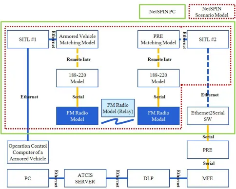
[image:3.595.306.548.423.617.2]We have been developing the NetSPIN (Network Simulator and Planner for INteroperability) that is the tool to evaluate timeliness and correctness of information exchange in the simulated battlefield communication environment, which is simulated using the OPNET [2-5].
Fig. 4. Interconnection between real systems and the NetSPIN
As shown in Fig. 4, we are willing to assess timeliness of transmitted messages through interconnecting both the NetSPIN and real systems such as the operation control computer of an armored vehicle and the server of the ATCIS (Army Tactical Command Information System). For it, the simulated model of a FM radio has developed in the NetSPIN based on the PRC-999K [6, 7]. To simulate the real FM radio that performs a cut-through relay, our proposed method is applied to develop the model of a FM radio.
B. Application of the proposed method
developed using the packet transmission method that the Zero packet is applied. The Zero packet has totally same structure with a real packet, but its size is 0.
Fig. 5. Modeling concept for the cut-through relay of a FM radio using the proposed method
The FM Radio_Tx produces the Zero packet that a packet size is set to 0 using packet generation mechanism of the OPNET, and transmits it with the real packet. In case a packet size is 0, the transmission delay of a wireless pipeline stage is 0, and the Relay 1 receives the Zero packet after a propagation delay from the transmission start time of the FM Radio_Tx.
The Relay 1 extracts the value of the field ‘real_pkt_size’ among packet fields of the Zero packet, and checks the size of the real packet. Next, it transfers the Copy packet to the Relay 2. The Copy packet is the packet that the size of the Zero packet is changed to it of the real packet, and the field ‘relayed_check’ is set to ‘relay’. Furthermore, the Relay 1 stores physical characteristic values of the following real packet and discards it.
The Relay 2 generates the Zero packet from the received Copy packet, and transmits it with the Copy packet to the FM Radio_Rx. Also, this process is able to be applied to the wireless relay network that is composed of multi relay stages to use a cut-through mode.
The FM Radio_Rx eliminates the received Zero packet, and performs processes to extract several information from packet fields of the following received Copy packet.
Using the inner field information of packets in a FM radio, the Relay 1, 2 and the FM Radio_Rx perform processes to store and update information in the hash table, which has physical characteristic values of the pipeline stage that is generated in the wireless section.
Through processes above described, the end-to-end transfer delay of a real packet that is produced in the cut-through relay communication of the real FM radio has accurately modeled in our network simulator.
IV. TEST AND EVALUATION FOR THE PROPOSED METHOD
A. Test environment
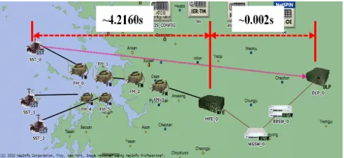
To assess the performance of the proposed method, the simulated network is constructed in the NetSPIN as shown in Fig. 6. In the simulated network, a transmitter is the SST (Surveillance System Terminal), a receiver is the DLP (Data Link Processor), a relay transmitter is the FM_1, and a relay receiver is the FM_2.
To transmit packets from the SST to the MFE (Multi Function Equipment), we use the simulated wireless and
cut-through relay network using simulated models of a FM radio. And, to transmit them from the MFE to the DLP, we use the simulated wired network that is composed of simulated models of a switch
Using the relay transmission of a packet based on the simulated network, the experimental value for a transfer delay of a packet is analyzed and compared with the analytical value for it.
[image:4.595.306.549.197.309.2]In our test, five packets are transmitted at each 100 s, the size of each packet is 2736 bit, and the transmission speed of a packet is 1200 bps.
Fig. 6. Simulated network topology for the test and evaluation
B. Numerical analysis
[image:4.595.306.548.495.606.2]Fig. 7 shows each value of the transfer delay between the SST and the MFE for the numerical analysis. Based on the numerical analysis of the transfer delay for the simulated cut-through relay network, the transfer delay of a packet between the SST and the MFE is about 4.216 s (= 0 s + 0.12 s + 0 s + D_p + 0.5455 s + 0 s + 0.12 s + 2.28 s + D_p + 1.15 s + 0 s). In this analysis, we assume that D_p is 0 s. And, the transfer delay of a packet between the MFE and the DLP is about 0.002 s, which is acquired through the simulation. Therefore, the end-to-end transfer delay between the SST and the DLP is about 4.218 s.
Fig. 7. Numerical analysis for a transfer delay
In Fig. 7, Tx_preamble is the transmitter preamble processing time, Tx_RF_lock is the transmitter RF(Radio Frequency) locking waiting time, Security_Tx is the security device processing time, Remote_Tx is the remote control device processing time, Tx_DTE_Wait is the DTE (Data Terminal Equipment) packet waiting time, and Dehop_time is the dehopping and receiving processing time. packet is the size of a packet, and its unit is the bit. d_rate is the transmission speed of a packet, and its unit is the bps (bit per second).
C. Test results and analysis
end-to-end transfer delay between the SST and the DLP is equal to the analytical value described above. Therefore, the performance of the proposed technique is verified.
TABLEI TEST RESULTS
Id of packets of the SST Tx Time of the DLP Rx Time Transfer DelayEnd-to-end
1 100.000 104.218 4.218
2 200.000 204.218 4.218
3 300.000 304.218 4.218
4 400.000 404.218 4.218
5 500.000 504.218 4.218
V. CONCLUSION
In this paper, to overcome problems of the existing network simulator that only supports the communication relay of a store-and-forward mode, we proposed the technique that is able to model precisely the relay procedure of a cut-through mode in a network simulator.
Using the proposed method, we have computed accurately the transfer delay of a real packet in a cut-through relay, the start time of the busy state of the network after relay, and the physical characteristic value that a real packet experiences. Furthermore, the proposed method has been applied to develop the model of a FM radio to use a cut-through relay mode, and based on it, the performance of the proposed technique has tested and verified.
REFERENCES
[1] Nuredin Ahmed, “System Level Modeling and Design of Hypergraph Based Wireless System Area Networks for Multi-Computer Systems,” Ph.D. dissertation, Dept. Elect. Eng., Univ. of Glasgow, Glasgow, Scotland, 2011.
[2] Sangil LEE, Sangheun SHIM, Myounggil AHN, Dongguk RYU, Jonghyun JIN, and Byoungin CHO, “Network M&S Techniques based on the Interworking of a Real System for the Interoperability T&E”, Korea Military Science Technology Conference, 2010.
[3] Jaeyoung CHEON, Sangil LEE, and Byoungin CHO, “Introduction for Network Simulation and Planning for Interoperability Tool”, Korea Military Science Technology Conference, 2009.
[4] OPNET Technologies, Inc., “OPNET Manual”, [Online]. Available: http://www.opnet.com
[5] OPNET Technologies, Inc. “Overview of OPNET Solutions for Network R&D”, OPNET Works, Session 1006, 2008.