An Approach to Creating and Maintaining
House-Watching Network in MANET
Jiahong Wang, Yuhiro Yonamine, Takashi Iokawa, Eiichiro Kodama, and Toyoo Takata
Abstract—It was found that in the disaster-hit area, a communication supporting system using the existing mobile ad hoc network techniques cannot function as expected and communication would be interrupted from time to time, since they have not taken into consideration the sleep operation that is a very frequently used means for users of mobile terminals to increase their battery life time. In order to solve the problem, this paper proposes a system model and two methods. The one is used to create a house-watching network taking charge of waking up the sleeping terminals, so that periodic or planned communication can be supported even though users freely get into sleep at their convenience. The other is used to incorporate the sleeping with the routing protocols, so that users’ consideration for other people can be technically supported, and they can know if their terminals are functioning as routers, and when sleeping buttons of their terminals can be pushed down safely without interrupting the relaying in progress, and so without interfering with others’ communication. These methods have been demonstrated to be effective by simulation experiments.
Index Terms—ad hoc network, sleep operations, house-watching network, routing and sleeping protocols.
I. INTRODUCTION
O
N March 11, 2011, an earthquake of magnitude 9.0, which was the largest one in Japan’s history, struck off the coast of the northern part of the country, churning up a devastating tsunami that swept over cities and farmland, and took away almost everything, including power supply systems and communication systems. Experiencing the dis-aster, we found that it becomes necessary for us to have a communication supporting system for the emergency use in the disaster-hit area.It is true that nowadays we have too many communication supporting systems to know which one to use. However, no one of them functioned as expected when the earthquake and tsunami occurred. The fact is that at that time, telephone, email, internet, and television became unavailable, and peo-ple were isolated from the outside world. Since no means of communication were available, they could not communicate with each other, and thus became very anxious that, e.g., whether the foods and water in hand were enough to survive the disaster, when the basic infrastructure for livelihood could be restored, and where medical cares could be provided. Such a communication supporting system was really necessary that could connect everyone together and so people could exchange information and relieve stress of each other.
We think that the Mobile Ad Hoc NETwork (MANET) can be a good candidate to serve a communication infrastructure in the disaster-hit area for emergency use. This is because
[image:1.595.342.514.168.289.2]The authors are with the Faculty of Software and Information Science, Iwate Prefectural University, Takizawa, Iwate, 020-0193 JAPAN, e-mail: [email protected].
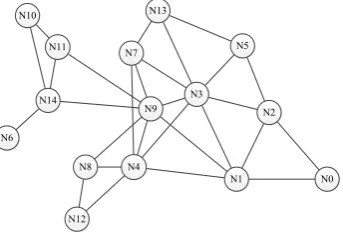
Fig. 1. In this example, terminalN9would function as a router for relaying data between, e.g.,N10andN2.
for MANET, we can use themobile terminalssuch as tele-phones, notebook type personal computers, and other mobile equipments (also called nodes thereafter) for communication. No power supply systems but the battery of mobile terminals, no center server for assisting communication, and no pre-determined plan for the network backbone are needed. We can have a network at any time and any place, and use the network as we do just before disaster happens.
It was found, however, in the disaster-hit area, commu-nication supporting systems based on the existing MANET technique cannot function as expected. The network would not last long enough, and the communication would be interrupted from time to time. This is because, on the one hand, mobile terminals are all battery-driven and the battery cannot be recharged due to the damaged power supply system, and on the other hand, the existing MANET technique has not taken into consideration the sleep operation of mobile terminal users that is very common and frequently-used means for them to increase their battery life time. For example, the owner of mobile terminalN9in Fig. 1 may just finish sending a mail to his / her friend and thus close his / her mobile terminal, resulting in that the communication between
N10 and N2 becomes interrupted, since N9 serves also as a router for relaying data. Due to the uncontrolled seeping operations we cannot have a stable and useable network.
them, and for how much time they should delay closing their mobile terminals so that the communication tasks over their mobile terminals could finish without interruption.
Then in order to have an effective communication support-ing system for the emergency use in the disaster-hit area, we have to solve two problems: maximize the lifetime of the ad hoc network as a whole, and make routing activities at the IP layer viewable to users. For the purpose, in this paper we present a system model and propose two methods. The one is used to create a house-watching network taking charge of waking up the sleeping terminals, so that periodic or planned communication can be supported even though users freely get into sleep at their convenience. The other is used to incorporate the sleeping with the routing protocols, so that users’ consideration for other people can be tech-nically supported, and they can know if their terminals are functioning as routers, and when sleeping buttons of their terminals can be pushed down safely without interrupting the relaying in progress, and so without interfering with others’ communication. Results of simulation experiments demonstrate the effectiveness of the proposed method.
In the rest of this paper, Section II formally define the problem. Section III gives algorithms to solve the problem. Results of a performance study are discussed in Section IV. Finally, Section V concludes the paper.
II. PROBLEMSTATEMENT
The problem to be solved in this research, as described in Section I, is formulated as follows.
Problem Statement. Consider such a mobile ad hoc net-work that is located at a disaster-hit area, consists of an administration center and a group of user mobile terminals driven by batteries, and batteries cannot be recharged due to the damaged power supply system. How to support com-munication on the network for as long time as possible is a problem. Our objective is two-fold. On the one hand, the life time of the overall network should approach the one when a mobile terminal is used solely for its owner’s purpose without the duty of relaying others’ data. On the other hand, a mobile terminal can get into sleep at his / her owner’s convenience to increase the battery live time, but the network can remain connected and users’ communication cannot be affected. An approach is to be devised to achieve these two objectives, and ensure such an application-oriented ad hoc network that a user can communicate with another user whenever he / she wants to.
For the first objective, a promising solution is to construct a Connected Dominating Set (CDS) [1]–[6], and to use the CDS-based routing. In general, a Dominating Set (DS) of a graph G = (V, E)is a subset V0 ∈V such that each node inV0−V is adjacent to at least one node inV0, and a CDS is a DS whose induced sub-graph is connected. CDS-based routing is such a routing method that selects certain nodes from the network as gateway nodes. These gateway nodes form a CDS and are responsible for routing within network. The CDS-based approach is widely used for constructing network backbones, and here can be used as a house-watching network. That is, we can take each CDS node as a watchdog node, and let other nodes sleep freely. However, we found existing approaches cannot help solve the problem
defined above satisfactorily. First, we need such a network that is of a well-defined structure, so that if a watchdog node fails to function due to, for example, battery problem or careless sleep operation, a human-intervention can be possible. Second, applications in the disaster-hit area require that a house-watching network should be initially constructed around the administration center, but migrate autonomously to the center site of the area so that the network diameter and number of watchdog nodes become minimized, and thus, the delay of broadcasting a message can be minimized and the number of sleeping nodes can be maximized. More importantly, fault-tolerance can be enhanced.
Some similar work can be found in [7]–[10], where a new factor called the diameter, which is the longest shortest path between any pair of nodes, is considered, and the problem is to minimize the diameter so that routing is easier and can adapt quickly to topology changes of a network. The difference from this research is that in this paper the diameter is the longest shortest path between the administration center or its proxy node and any other nodes, the “center” of network has to be located autonomously, and by which the diameter is minimized. Some other low cost approaches for constructing CDS have been proposed [11]–[16]. For the defined problem, however, these approaches could not be very helpful.
For the second objective, we have not found any research results dealing with the subject of integrating the sleeping and the routing protocols. In fact, they have been consid-ered as two independent concepts for different purposes, and integrating them has been considered unnecessary and impossible. We found that, however, for the disaster-hit area the integration is really necessary so that a more effective and friendly communication supporting system can be obtained.
III. HOUSE-WATCHINGNETWORK ANDROUTING
AWARESLEEPINGPROTOCOL
In this section, we first provide notations, definitions, and some fundamental concepts used in the subsequent sections. Then we propose an approach to solving the problem defined in Section II.
A. Definitions and Preliminaries
We use an undirected graph G= (V, E) to represent an ad hoc network, whereV is the set of nodes and(u, v)∈E
is the transmission link between nodes u and v. That is,
(u, v)is in E if nodes uandv are within the transmission range of each other. Without losing generality, we assume that the nodes inV are located in a plane, and all nodes are homogeneous, meaning that they have the same transmission range.
We assume that in a disaster-hit area, there will an administration center that takes charge of running it. The administration center can assign some other node as aproxy
to take some of its duties such as broadcasting messages. In this paper we considerdiameteras a metric to evaluate the constructed house-watching network, which is defined as follows.
TABLE I
NOTATIONS USED IN THIS PAPER
notations meanings
SHW N The house-watching network.
Administration Center The node being responsible for initializing
NAdminC the house-watching network.
Nproxy The proxy node of administration center.
u.Diameter Diameter of nodeu.
u.House-Watch True ifuis a house-watching node
u.color A field for assisting construction ofSHW N
proxy of it. The diameter of G is the length of the longest shortest paths between anyu∈V and NA or NP.
We think that a house-watching network should be some kind of CDS as defined below, with as many nodes as possible being able to sleep, and as few nodes as possible being watchdog nodes. Watchdog nodes should be able communicate with the administration center or its proxy by the shortest route, so that important messages can be broadcast to every node with little delay.
Definition 2(DS). A Dominating Set (DS) ofG= (V, E)is such a node setV0 that ∀(v, w)∈E,v∈V0 orw∈V0.
Definition 3 (CDS). A CDS ofG= (V, E)is such a DS of G that the subgraph of G induced by the nodes in this set is connected. The size of a CDS is equal to its node number.
For a given ad hoc networkG, finding a house-watching network over Gwill be addressed below.
Definition 4 (HWN: House-Watching Network). An HWN ofG= (V, E)is such a CDS of G that has a tree structure and is of the minimal diameter.
B. System Model
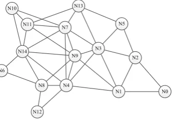
We model the system for solving the problem defined in Section II as an ad hoc network G= (V, E) as shown in Fig. 2. A house-watching network as defined in Definition 4 is constructed. All users except the HWN ones, or all users except the proxy and the administration center can go to sleep. The sleeping nodes will be woken up in specified time interval, or according to totalized user requests.
When users are woken up, they can communicate with each other, and then go to sleep again to save their batteries. At that time, they may make requests to the administration center or its proxy to specify when they should be woken up the next time.
We also noticed that uncontrolled sleeps may make the ad hoc network unconnected, and other users’ communications interrupted. Fortunately, we also found that people in the disaster-hit area would be like to help each other in various aspects, including the maintenance of an ad hoc network for their own communication. Therefore, the routing table is assumed to be viewable to users (e.g., N9 in Fig. 2), and a user can make his / her decision of pushing down sleep button according to information from the IP layer, so as to not interfere with the users (e.g.,N14andN0in Fig. 2) who are using the node for relaying data.
To be not blocked for too long time, we assume that the users who are communicate with each other could indicate
DATA Flag (1: interruptible
/ 0: uninterruptible)
Application TCP
[image:3.595.47.294.76.179.2]IP
Fig. 2. An example for illustrating the system model. NodeN14andN0 are exchanging messages via nodeN9.
whether other users can push down their sleep buttons without any negative effect by setting a sleeping-save flag in the IP packets. UserN9, for example, may be so kind as to not trouble usersN14andN0by pushing down sleep button when he / she make sure the action is save by checking that sleeping-save flag. The time interval between two adjacent interruptible IP packets is called as a session as defined below.
Definition 5(Communication Session). A session of a com-munication task is the time interval between two IP packets which sleeping-save flags have been set to 1. Assume that sleeping-save flags of the first and the last IP packets are always set to 1.
C. The Algorithm HWN: House-Watching Network
The algorithm for constructing a house-watching network is given in Function 1. An administration center will use this function to create a house-watching network. Symbols used in the algorithm is summarized in Table I.
D. An Example for Illustrating HWN
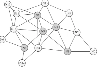
[image:3.595.344.513.581.699.2]In this section we give an example to illustrate the al-gorithm given above. Assume we have an ad hoc network shown in Fig. 3, where nodeN0is the administration center.
Fig. 3. An ad hoc network for illustrating HWN.
Then the algorithm will initially construct the house-watching network shown in Fig. 4.
Function 1 Construct a house-watching network Require: A set of mobile nodes
Ensure: A house-watching network as defined in Def. 4
1: Set Nproxy−pre and Nproxy to NAdminC, Nproxy−pre .Diameterto infinite, andSHW N−pre to∅.
2: Color all nodes white. SetNproxy.House-Watchto false,
Nproxy.Diameterto 0, andSHW N to{ Nproxy }. 3: For each nodeN ∈SHW N such thatN.House-Watch is
false, setN.House-Watch to true, and do the following.
4: Color nodeN black, each white childuof N grey, and setu.Diameter to(N.Diameter + 1).
5: Each grey node invites its white child nodes to join, and
sendsN the set of its 1-hop white children.
6: N selects such grey nodes as temporary members of
SHW Nthat they have more children (denoted asNtemp), one by one until all children of all grey nodes have been covered. Then, the selected nodes are notified.
7: Ntemp invites its white child nodes to join again, and each child node elects suchNtempas its parent that has more child nodes than any others. Ntemp.House-Watch is set to false, and added toSHW N.
8: Repeat steps 3 - 8 until all nodes have been colored black or grey.
9: If Nproxy.Diameter is less than Nproxy−pre.Diameter, then replace Nproxy−pre, Nproxy−pre.Diameter and
SHW N−pre withNproxy,Nproxy.Diameter andSHW N respectively, and replaceNproxywith such a child node of it that is on the diameter path, and repeat steps 2 - 9.
10: Return SHW N−pre as a house-watching network, with diameterNproxy−pre.Diameter and proxyNproxy−pre.
the administration center, and we have the house-watching network shown in Fig. 5.
[image:4.595.340.513.60.177.2]Because the path<N1,N9,N14>is the longest path, in the next step in pace of N0, N9 becomes a proxy node of the administration center, and we have the resulting house-watching network shown in Fig. 6. Both the house-house-watching networks shown in Figs. 5 and 6 have five nodes, but that shown in Fig. 6 is of a shorter diameter.
Fig. 4. Stage 1 of Func. 1.N0 is the administrator center.
IV. PERFORMANCEEVALUATION
Simulation experiments have been done to study perfor-mance of the proposed approach. Network Simulator-2 were used. This section describes simulation environment, presents and discusses simulation results.
Fig. 5. Stage 2 of Func. 1.N1is a proxy node of the administration center.
Fig. 6. Stage 3 of Func. 1.N9is a proxy node of the administration center.
TABLE II
EXPERIMENTRESULTS FOREXPERIMENTI
Experiment Number House-watching Diameter of nodes network size
1 40 13→10 5→3
2 50 14→14 5→4
3 60 13→13 5→5
4 70 11→10 4→2
5 100 16→13 3→2
A. House-Watching Network Size and Diameter
In this experiment (Experiment I), the field configuration is set to 1000 m×1000 m square. Five experiments are con-ducted with total 40, 50, 60, 70, and 100 nodes respectively. Nodes are randomly placed on the plane. Transmission range of each node is set to 250 m.
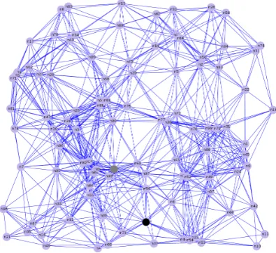
Experiment results are summarized in Table II. Topology corresponding to Experiment 1, 2, 3, 4, and 5 is given in Figs. 7, 8, 9, 10, and 11, respectively. Node 0 (the black node shown in Figs. 7 - 11) is taken as the administration center, and the grey nodes are the proxy nodes.
Comparing Figs. 7 - 9 with Figs. 10 - 11, it is known that if nodes are more evenly distributed, a smaller diameter can be achieved. This is because that, on the one hand, the algorithm can more effectively find the center of the area, if it has a well defined one. On the other hand, as shown in Fig. 9, in some cases the diameter could not be reduced any way. For this, some other kind definition of the “center of an area” than the “minimal diameter” may be more appropriate.
B. Session Size and Its Determination
[image:4.595.342.516.217.339.2] [image:4.595.84.255.556.671.2]Fig. 7. Experiment 1: number of nodes is 40.
Fig. 8. Experiment 2: number of nodes is 50.
Fig. 9. Experiment 3: number of nodes is 60.
[image:5.595.327.525.283.464.2]Fig. 10. Experiment 4: number of nodes is 70.
Fig. 11. Experiment 5: number of nodes is 100.
The field configuration is set to 500 m ×500 m square with total 50 nodes. Nodes are randomly placed on the plane. Transmission range of each node is set to 100 m. For traffic model, one node at one corner of the field is used to send files continuously to another node at the opposite corner.
As expected, experiment results show that larger session size increases average waiting time. For example, when we increased the session size from 50 packets to 200 packets, waiting time increased from about 1.1 to about 1.8 second.
Interestingly, it is also found that, in the case that more nodes are going to sleep, larger session size tends to increase packet arrival ratio. For example when we increased the session size from 50 packets to 200 packets, in the case of 5 nodes going to sleep, packet arrival ratios remained almost unchanged. In the case of 20 nodes going to sleep, however, packet arrival ratio increased from about 71% for size 50 to about 80% for size 200.
[image:5.595.70.269.294.511.2] [image:5.595.63.270.508.729.2]V. CONCLUSIONS
We have addressed the subject of communication problems at the disaster-hit area. It is found that in the disaster-hit area, a communication supporting system using the existing mobile ad hoc network techniques could not function as expected and communication processes would be interrupted from time to time, since they have not taken into consider-ation the sleep operconsider-ations of mobile terminals that are very frequently used means for mobile users to increase their battery life time. We have presented a system model for solving this problem, and proposed two methods.
Simulation experiments have been conducted to study performance of the proposed approach. Experiment results have shown that using the proposed approach, only a few terminals need to be powered on and all the others can go to sleep mode safely, and when a terminal user wants to sleep, he / she can have the chance to decide at what time the sleeping button should be pushed down so that other users would not be affected by his / her sleeping.
REFERENCES
[1] B. Das and V. Bharghavan, “Routing in ad-hoc networks using minimum connected dominating sets,” inProc. IEEE International Conference on Communications (ICC’97), Montreal, Canada, 1997, pp. 376–380.
[2] B. Das, R. Sivakumar, and V. Bharghavan, “Routing in ad hoc networks using a virtual backbone,” inProc. IEEE International Conference on Computer Communications and Networks (IC3N’97), Las Vegas, 1997, pp. 1–20.
[3] B. Das, R. Sivakumar, and Vaduvur, “Routing in ad hoc networks using a spine,” inProc. IEEE International Conference on Computers and Communications Networks (IC3N’97), Las Vegas, NV., 1997, p. 34. [4] C. Yu-Liang and H. Ching-Chi, “Routing in wireless/mobile ad-hoc
networks via dynamic group construction,” Mobile Networks and Applications, vol. 5, no. 1, pp. 27–37, 2000.
[5] J. Wu and H. Li, “On calculating connected dominating set for efficient routing in ad hoc wireless networks,” inProc. International workshop on Discrete algorithms and methods for mobile computing and communications (DIALM’99), Seattle, Washington, USA, 1999, pp. 7–14.
[6] R. Sivakumar, P. Sinha, and V. Bharghavan, “Cedar: a core-extraction distributed ad hoc routing algorithm,”IEEE Journal on Selected Areas in Communications, vol. 17, no. 8, pp. 1454–1465, 1999.
[7] Y. Li, D. Kim, F. Zou, and D.-Z. Du, “Constructing connected dominating sets with bounded diameters in wireless networks,” in
Proc. International Conference on Wireless Algorithms, Systems and Applications, 2007. (WASA’2007), Chicago, IL, 2007, pp. 89–94. [8] D. Kim, Y. Wu, Y. Li, F. Zou, and D.-Z. Du, “Constructing
mini-mum connected dominating sets with bounded diameters in wireless networks,”IEEE Transactions on Parallel and Distributed Systems, vol. 20, no. 2, pp. 147–157, 2009.
[9] S. M. Aur´elio and J. J. Garcia-Luna-Aceves, “Bounded-distance multi-clusterhead formation in wireless ad hoc networks,”Ad Hoc Networks, vol. 5, no. 4, pp. 504–530, 2007.
[10] V. S. Anitha and M. P. Sebastian, “Scenario-based diameter-bounded algorithm for cluster creation and management in mobile ad hoc net-works,” inProc. IEEE/ACM International Symposium on Distributed Simulation and Real Time Applications (DS-RT’09), Singapore, 2009, pp. 97–104.
[11] F. Dai and J. Wu, “An extended localized algorithm for connected dominating set formation in ad hoc wireless networks,”IEEE Trans-actions on Parallel and Distributed Systems, vol. 15, no. 10, pp. 908– 920, 2004.
[12] J. Bolla and D. Huynh, “Adapting connected d-hop dominating sets to topology changes in wireless ad hoc networks,” inProc. IEEE In-ternational Performance Computing and Communications Conference (PCC’06), Phoenix, AZ, USA, 2006, pp. 207–214.
[13] K. Sakai, M. T. Sun, and W. S. Ku, “Message-efficient cds construction in manets,” in Proc. IEEE International Symposium on Wireless Pervasive Computing (ISWPC’10), Modena, Italy, May 2010. [14] H. Y. Yang, C. H. Lin, and M. J. Tsai, “Distributed algorithm for
efficient construction and maintenance of connected k-hop dominating sets in mobile ad hoc networks,” IEEE Transactions on Mobile Computing, vol. 7, no. 4, pp. 444–457, 2008.
[15] J. Wu, F. Dai, and S. Yang, “Iterative local solutions for connected dominating set in ad hoc wireless networks,”IEEE Transactions on Computers, vol. 57, no. 5, pp. 702–715, 2008.