Abstract—In this paper, a new hybrid systems framework to behavior control of nonholonomic AGV is presented. Instead of using the traditional hierarchical structure or the hybrid automata separately, both were combined in this paper. This framework has the 3-layered hierarchical structure containing a hybrid automata of the motion control as the middle process. The hybrid automata has three states, stop, line path following and circle path following. Complex behavior of AGV is decomposed into discrete control sequences by discrete behavior planning from the top layer and implemented by the hybrid automata. The lower process is the AGV plant which is decoupled by input-output nonlinear feedback linearization. This framework not only avoids the state explosion problem of automation, but also reduces the control complexity and ensures the performance of the AGV behavior control system. The simulation results to the motion control, parking behavior and deadlock resolution of the AGV verify the validity of this framework.
Index Terms—Automated Guided Vehicle (AGV), Behavior control systems, hybrid systems, Nonholonomic constrains, Nonlinear control
I. INTRODUCTION
utomated guided vehicle (AGV) is a kind of simple mobile robots, which is powered by battery and could be controlled by programming. AGVs can be used widely for automated transportation in various industrial and service fields such as in factories, ports, banks, airport, post offices, etc. It occupies a center to material handing of the intelligent logistic systems due to its autonomous characteristics. AGVs not only reduce the labor costs, but also ensure the transport efficiency and security.
Manuscript received June 17, 2011; revised June 25, 2011. This work was supported by Chinese National Natural Science Foundation under Grant 50875090, 50905063 and Development Program of China (863 Program, Grant No.2009AA04Z111).
Jinhua Ye is with the school of Mechanical & Automotive Engineering, University of South China University of Technology, China. (phone: +86-20-87114637; fax: +86-20-87114637; e-mail: [email protected]).
Di Li is with the South China University of Technology, China, Institute of Mechatronic Engineering. She is also with the school of Mechanical & Automotive Engineering, University of South China University of Technology, China. (phone: +86-20-87114637; fax: +86-20-87114637; e-mail: [email protected]).
Song Li is with the school of Mechanical & Automotive Engineering, University of South China University of Technology, China. (e-mail: [email protected]).
Xiaokang Liu is with the school of Mechanical & Automotive Engineering, University of South China University of Technology, China. (e-mail: [email protected]).
Yage Hu is with the Chinese Christian School, America. (e-mail: [email protected]).
As the increasing complexity of AGV systems in commercial and industrial scenarios, control and coordination of the AGVs become much more difficult under uncertain dynamic environment. Along with higher requirements of complex task, the increased ability and responsiveness for AGV con- trol systems have been received much consideration in the last decade. The multiagent-based or behaviors-based approaches have been the focus of the researchers. For examples, Choudhary et al. [1] proposed a multiagent-based framework representing zone controlled AGV environment incorporating various behaviors like path generation, collision and deadlock avoidance, etc. Christopher et al. [2] implemented behaviors- based intelligent distributed fuzzy logic control systems integrating the presentation of human knowledge to a meca- num wheeled AGV, the navigational and collision avoidance behaviors of AGV were controlled by using IF-THEN rules. The above mentioned approaches could achieve improved reliability and reduce complexity of AGV control systems to some extent. However, the AGV is a complex nonlinear system with nonholonomic constraint. It can not be controlled by smooth linear time invariant controls laws [3], which most of the assumptions made in the controls literature are not satisfied. It is especially hard to provide provable guarantees on safety and performance to its behavior control systems (BCS) which control the AGV to perform various tasks in uncertain dynamic environment. One successful approach is to decompose it into hybrid systems that intermix discrete modes and continuous dynamics. Recently years, a rapid growth of interest in hybrid systems has developed efficient tools for synthesis and analysis of such complex systems. This hybrid, hierarchical approach to the design and control of BCS for AGV has proven to be very successful. For examples, Kress-Gazit et al. [4] applied linear-temporal logic specifica- tions for generating robot behaviors. Hua et al. [5] applied motion description languages to solve the pose stabilization problem of nonholonomic wheeled mobile robots. Gayan et al. [3] explained a hybrid control strategy developed to coor- dinate multiple autonomous mobile robots with nonholo- nomic constraints in an obstacles populated environment. Wang et al. [6] adopted a hybrid input/output automata to decompose the behavior control systems of mobile robots and different languages were used to define the behavior speci- fications. Hua et al. [7] addressed a 3-layered hierarchical hybrid control structure to pose stabilization controller for wheeled mobile robots. Pu et al. [8] resolved the parking problem for wheeled mobile robot by using hybrid automata- based approach.
Traditional hierarchical structure [7, 9, 10] that each layer of controller will be designed and implemented separately can simplify the design process of complex systems, but due
A Hybrid System Framework to Behavior
Control of Nonholonomic AGV
Jinhua Ye, Di Li, Song Li, Xiaokang Liu and Yage Hu
to lacking of interaction between layers, it may have difficulty to control the complex BCS with various tasks. By using hybrid automata only [8, 11], the interaction between discrete and continuous parts of the system would be enhanced, however, with the growing number of complex tasks, the number of states would increase dramatically, this may cause a so called state explosion problem and make systems uncontrollable. Furthermore, the model in each state is usually rather arbitrary without exact specification, take [8] as an example, the mo- tion trajectory of AGV is arbitrary without reasonable restric- tions in each state, which may lead to some uncertain behaviors in some situations. To solve these problems, an innovative hybrid systems framework to BCS of Non- holonomic AGV is proposed in this paper. It has a unified 3-layered hierarchical structure which consists of discrete behavior planning (DBP) for the higher process, hybrid automata for the middle process and AGV plant for the lower process. In this framework, the complex behaviors (e.g., parking, deadlock resolution) control of AGV supervised by higher process will ultimately be decomposed into the path following to several straight lines and circular arcs. So, we get few continuous dynamics states for the hybrid automata in middle process, and each discrete state has a deterministic model, the motion trajectory of AGV is determined as straight line or circular arc. When adding new behaviors, we only need to add new discrete sequences in the layer of DBP, the number of states will not increase. In addition, this kind of slow switch systems has been proven to be stable as the subsystem of each model is stable [12]. The nonlinear plant with nonholonomic is decoupled by using input-output feedback linearization [13], and a set of switch sub-systems is derived from the rest part. This framework takes the essence of traditional hierarchical structure and hybrid automata, but discards the dross of them, which could also support the use of existing map-based control [14] or reactive control [2] tech- niques for AGV.
This paper is organized as follows. In section II, the new hybrid systems framework to BCS of nonholonomic AGV is introduced. Then in section III the development of each layer for the 3-layered structure is explained, how this framework can be used to solve the motion control, parking behavior and deadlock resolution is also elaborated. The simulation results are present in section IV. Concluding remarks end the article in section V.
II. HYBRID SYSTEM FRAMEWORK OF AGV
A. Modeling of Nonholonomic AGV
Without loss of generality, by using Lagrange formulation, the general dynamics model of AGV with n-dimensional generalized coordinates q subjected to m nonholonomic independent constraints can be described as a generalized mechanical system that are in the form
T
m d
M(q)q V (q, q)q F(q) G(q) τ
B(q)τ A (q)λ
(1) A(q)q 0 (2) where M(q) n n is a symmetric positive define inertia matrix of the system. V (q, q)m n n is a centripetal and coriolis forces matrix. F(q) n1 is a surface friction
matrix. G(q) n n is a gravity matrix. τd n1 is the bounded unknown disturbances matrix. B(q) n (n m) and τ (n m ) 1 are the input transformation matrix and input vector. A(q) m n and λ m1 is the kinematics constraints matrix and generalized forces vector.
Here, we assume that the AGV move in a horizontal plane without considering the friction and ignore the unknown dis- turbances, therefore, F(q) , G(q) and τd are all zero matrix.
Let S(q)
s q1( ) sn m ( )q
be the full-rank matrix made up of a set of smooth and independent vectors fields inN(A), i.e.,
A(q)S(q) 0 (3) thus, it is possible to find a set of auxiliary input vector of time functions, v(t) (n m ) 1 , such that
q S(q)v(t) (4) Differentiating (4), then substituting it into (1) and premultiplying by
S
T, we have1
( T ) T( )
m
v S MS S MSv V Bτ (5) Let
T
T T
x q v , from (4) and (5), we obtain the state space representation of dynamics model for nonholonomic AGV as
1
Sv 0
x τ
f H (6)
where 1
1 ( ) ( )
T T
m
f S MS S MSv V , H(S MST )1S BT . Proper control laws can be developed by utilizing (6), which we discuss in next section.
b
2 d
r 2
Fig.1. Structure of two-rear-drive nonholonomic AGV
The configuration of the AGV plant can be described by five generalized coordinates as follows
TP P A B
x y
q (7)
where
xP yP
is the coordinates of the COM P,A andB
are the angular displacements of driving wheels A and B respectively. For the pure rolling and no slipping nonholonomic condition states, the kinematic constraints equations of the AGV is given by
sin cos 0
P P
x y d
(8)
cos sin
P P A
x y br (9)
cos sin
P P B
x y br (10) From (8), (9), (10), the kinematic constraints matrix in (2) is given by
sin cos 0 0
cos sin 0
cos sin 0
d b r
b r
A(q) (11)
then, it is easy to verity that the following matrix
satisfies (3), where the constant cr/ 2b.
B. Hybrid Automata
The hybrid automata can be considered as a finite state machine, or finite automation, with a linear or nonlinear conti- nuous dynamical system embedded in each discrete location, such systems evolve continuous evolution according to differential equations as well as instantaneous transitions triggered by external or deliberate events sensed. Hybrid automation model is useful in specification, analysis, verification or synthesis for complex hybrid system. The hybrid automata adopted in this paper is defined to be the tuple.
( , , , , , , , , , , , )
H Q X U Y init f h I E G R (12) in which Q
q q1, 2,
is a set of discrete states. X is the state space of the continuous variables. U is a finite collec- tion of continuous input variables. Y is a set of continuous output variables. Init Q X is a set of initial states.
1, 2,
f f f is a vector field. h
h h1, 2,
is an out- put map.I
is an invariant set, the system may flow withini
q only if XI q( )i .E Q Q is set of discrete jumps. G
is a guard condition, when (G eij) is true, the system may instan- taneously take a discrete transition from current state
qi to next state qj. R is a reset map, assigns to each state a set of admissible inputs.
C. Hierarchical Hybrid Control Architecture of AGV
In the face of dynamic changes in the environment and des- cription requires to complex task, the whole AGV system in- cludes both continuous activities and discrete-event features and the developed continuous dynamic subsystems must be switch between. So a hybrid system is developed, which can greatly simplify the behavior planning and control by generat- ing plans at the level of the discrete modes.
The hybrid systems control architecture considered here is a 3-layered hierarchical structure as depicted in Fig.2.
The plant layer. The AGV system to be controlled be- longs to a special class of Euclidean SE(2) dynamic systems. Since it is nonholonomic and couldn’t be asymptotically stabilized to a single equilibrium point by any continuous feedback control. So, the input-output nonlinear feedback linearization and input-output decoupling are applied to make system controllable in this layer.
The hybrid automata layer. In this layer, the AGV con- troller is modeled as a hybrid automata to reduce the difficu- ties of motion control with nonholonomic constraints and allows for the application in various complex task domains. In order to simplify control mode sequence generation and avoid the state explosion problem, it is more desirable to reduce the number of control modes of the hybrid automata. Moreover, based on the fact that the shortest path for AGV are composed of circular arcs and straight lines, complex path for AGV can be decomposed into piecewise continuous path with discon- tinuities in curvature [13]. Thus, we model the hybrid auto- mata with three specific states: q1: stop, q2: path following to a straight line and q3: path following to a circle. By using path following, the starting posture of AGV need to be as close to the reference path as possible, however, it could have more stable speed than by using trajectory tracking, so it is more suitable to practical applications. This layer serves as the communication between the AGV plant and the behavior planning layer. The hybrid automata would evolve according to the discrete sequence of operations from higher process and give the control input to the plant.
The behavior planning layer. This layer is the top layer, which responses to the environment, communicates with the hybrid automata layer. It is concerned with the planning of the AGV behavior and supervises the execution of a mission plan. In this layer, the behavior specification of AGV can be des- cribed by many methods and languages, such as automation, linear-temporal logic method, pseudo code, C language, etc. Here, the pseudo code is used, in which the specification described consists of behavior decomposition strategy, path planning, control parameters, transition rules and trigger sequences.
III. IMPLEMENTATIONS
A. Control Laws of Plant
The AGV system modeled as continuous-time system described by (6) is a multi-input-multi-output (MIMO) non- linear system, it may be input-output linearizable if a set of
( cos sin ) ( sin cos ) 1 0
( cos sin ) ( sin cos ) 0 1
T
c b d c b d c
c b d c b d c
output equation is chosen appropriately. Utilizing the non- linear feedback control, let
1
( )
τ H U f (13) where τ
τA τB
T is the control torque to two actuatorsof AGV, H is the pseudo inverse matrix of H, U 2 1 is a new auxiliary input vector associated with the output equation.
Substituting (13) into (6), the state equation simplifies to the form of
x k(x) g(x)U (14)
Fig.2. Hybrid system architecture of maneuvers for an AGV
where
Sv k(x)
0 ,
0 g(x)
I
Let the output equation be denoted by
T 1 2
y h(q) h (q) h (q) (15) and the full rank decoupling matrix P(x) 2 2 for the system be denoted by
h P(q) S(q)
q (16)
then defining a new auxiliary input vector u 2 1 and utilizing the following state feedback
1
( )
U P u Pv (17) we achieve input-output linearization,u can be designed by the linear controller, we use PD controller in this paper. Let error e h desied h, the PD controller is given as
desied p d
u y
k e k e
(18) where kp 2 2 and kd 2 2 are constant gains to ensure the convergence of the control errors. The schematic block diagram of the plant is shown in Fig.3.τ
U v
u
q qq
1
P
P
H
1
f S(q)
Fig.3. Control schematic for motion control of the plant
B. Switching Models of Hybrid Automata
The AGV controller shaded as oval in Fig.3 is modeled by a hybrid automata with three states. We now describe the con- tinuous dynamics within each discrete state. Considering the problem of path following, by following the conventional wisdom in which one drives a car. Two requirements should be considered, the car should pursue the path as closely as possible and travel the path with a given forward velocity. Let us define h1 be the shortest distance from the point P to the reference trajectory and h2 be the AGV forward velocity of point P along the XR-axis.
For the path following of a straight line described by 0
desied desied
Ax By C , the output equation is
_1( , , ) 2 2
desied desied
l P P
Ax By C
h x y
A B
(19)
_ 2( ) cos sin ( )
2
l P P A B
r
h v x y (20) Likewise, if the path is a circle with center
(
x
desied,
y
desied)
and radiusR
, the output equation is_1
2 2
( , , )
( ) ( )
c P P
P desied desied
h x y
x x yP y R
(21)
_ 2
( )
_ 2( )
c l
h
v
h
v
(22) then, utilizing (16), we can obtain the decoupling matrix for straight line and circle respectively, they are( )
T l
l
P (q) J S q J (23) ( )
T c
c
P (q) J S q J (24) where
2 2
0 0 0
l
A B
A B
J ,
2 2
0 0 0
( ) ( )
P desied P desied c
P desied P desied
x x y y
x x y y
J ,
2 2
r r
1
1
_1 _ 2
( )
: 1
l l
l l
q
h h
I turn
x k(x) g(x)U U P u P v y
2
1
_1 _ 2
( )
: 2
c c
c c
q
h h
I turn
x k(x) g(x)U U P u P v
y
0 0 0 0 0
: 0
q
I turn
x U y
2 turn
0 turn 1 turn
1 turn
0 turn
2 turn
2
turn
1 turn
0 turn
Fig.4. Hybrid automation model for controlling the AGV In Fig.4, the transaction conditions turni i( 0,1, 2) is de- termined by the arrival of switching points which satisfy the restrictions, turn0 may also be true for emergency. For presence of position errors, the transaction condition is true when the distance from point
P
to switching point is within a tolerance. Depending on a set of discrete sequences ofturn and switching points from layer of behavior planning, the switching is triggered between the states.
C. Behavior Supervise and Control of AGV
This section we will consider the applications of the hybrid system framework described above in motion control, parking behavior and deadlock resolution for AGV.
(a) Motion control of AGV
The motion control is the foundation for all other activities of AGV, the complex behaviors of AGV are ultimately im- plemented by motion control. For the nonholonomic AGV, here, its desired motion manner including moving (backward, forward), turning (left, right), and stationary are chosen by control modes of hybrid automata, the decision of the next control mode is as shown in Fig.5., when the COM P reaches to the switching point, each control specifications of motion manner is described as follows.
Motion Control Specifications IF: Forward or backward;
SET: Turn=1;
THEN: Given the line path parameters A, B and C. For Forward, the velocity is positive. For backward, the velocity is negative.
IF: Left turn or right turn;
SET: Turn=2;
THEN: For left turn, given the circle path parameters center
O
l and radiusR
l. For right turn, given the circle path parameters centerO
r and radiusR
r. And for forward, the velocity is positive. For backward, the velocity is negative.IF: Stationary;
SET: Turn=0;
THEN: Given all the path parameters to zero. The velocity is zero.
DO: Path following
The center
O
l andO
r are given bycos( / 2
)
C S
x
x
R
sin( / 2
)
C S
y
y
R
where
(
x
C,
y
C)
is the coordinates of circle center,R
is the circle radius,(
x
S,
y
S)
is the coordinates of switch point.(b) Parking behavior
Parking behavior is usually attributed to posture stabiliza- tion problem which has been regarded as a very difficult pro- blem. Here, we attempt to solve the parking problem using our hybrid system framework. Figure 6 shows the parking behavior of AGV from point S to origin K, its specifications can be described as follows.
Parking Behavior Specifications
INITIAL: The path parameters of lines SD, EF and JK, The path parameters of circles O1, O2 and O3. The position coordinates of points D, E, F, G, H, I and J. The forward velocity;
START: Forward;
IF: Reach D THEN: Forward right turn;
IF: Reach E THEN: Forward;
IF: Reach F THEN: Forward left turn;
IF: Reach H THEN: Forward right turn;
IF: Reach J THEN: Forward;
IF: Reach K THEN: Stationary.
All the circles have the same radius
R
. The distance from point D to XI-axis is5
R
, from points F, H and J to YI-axis isR
.l
O
r
O
Fig.5. Motion control of AGV Fig.6. Parking behavior of AGV (c) Deadlock resolution
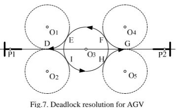
A traffic control scheme for multiple AGVs aims for a collision free motion plan, the collision should be predict and resolved well in advance, however, it is more flexible that the collision could be resolved dynamically. Figure 7 shows the dynamic deadlock resolution for head on collision of two AGVs under our hybrid system framework, its specifications is given as follows.
Deadlock Resolution Specifications
IF: The distance of AGV P1 and P2 is equal to DG=
2 3
R
;INITIAL: The path parameters of circles O1, O2, O3, O4 and O5. The position coordinates of points D, E, F, G, H and I. The forward velocity;
AGV P1: Forward right turn
IF: Reach I THEN: Forward left turn;
IF: Reach H THEN: Forward right turn;
IF: Reach G THEN: Forward;
AGV P2: Forward right turn
IF: Reach E THEN: Forward right turn;
[image:6.595.373.492.49.203.2]IF: Reach D THEN: Forward.
Fig.7. Deadlock resolution for AGV
All the circles have the same radius R which must be greater than the swing radius of AGV. The points E, F, H, I are the common tangent points of two circles.
IV. SIMULATIONS
The validity of our approach is verified by simulation, the simulation codes are written in Matlab M file. The fifth order Runge-Kuntta integration routine is used with the integration step setting to 0.001s. The AGV starts with a forward velocity of 1.414m/s.
[image:6.595.80.260.86.196.2]Figure 8 shows how the AGV follows a line path, then a circular path when it starts with a posture
(0, 4.1,
/ 4)
under the control of hybrid automata. We can see that the output velocities of left wheel and right wheel are very smooth.Fig.8. Simulation result of path following for AGV using hybrid automata Figure 9 and figure 10 show how our hybrid system frame- work to accomplish the parking behaviors and deadlock resolution for AGV. Related parameters are given as follows.
For parking behaviors, the starting posture of AGV is
(6.1,10, 2 / 5)
S
.1.5
R
m
,O
1(4.5, 7.5)
,O
2(1.5, 4.5)
,O
3(1.5,1.5)
. For deadlock resolution, the starting posture of AGV is1( 2, 4.01, 0)
P
,P
2(13, 4.01, )
.2
[image:6.595.328.535.237.375.2]R
m
,D
(5 2 3, 4)
,G
(5 2 3, 4)
.Fig.9. Simulation result of parking behavior for AGV under the hybrid system framework
Fig.10. Simulation result of deadlock resolution for AGV under the hybrid system framework
V. CONCLUSION
This paper introduces a new hybrid systems framework for the behavior control of AGV with nonholonomic constraints. It has the 3-layered structure including a hybrid automaton of motion control with three states: stop, line path following, circle path following. The complex behavior of AGV is decomposed into discrete control sequences by the top layer of DBP and implemented by the hybrid automata in the middle layer. The input-output nonlinear feedback lineari- zation is applied to make the AGV plant controllable in the lower layer. This approach not only reduces control com- plexity of the BCS for AGV, but also avoids the state explosion problem. The simulation results of the motion control, parking behavior and deadlock resolution of the AGV demonstrated the feasibility of this framework. In the future work, we will implement this framework to pioneer P3 robots.
REFERENCES
[1] S. C. Srivastava, S. Kumar, A. K. Choudhary, and M. K Tiwari, “Development of an intelligent agent-based AGV controller for a flexible manufacturing system,” International Journal of Advanced Manufacturing Technology, vol. 36, no. 7-8, pp. 780–797, 2008. [2] C. M Kumile, and N. S Tlale, “Intelligent distributed fuzzy logic
control system(IDFLCS) of a mecanum wheeled autonomous guided vehicle,” in Conf. Rec.2005 IEEE Int. Conf. Mechatronics & Automation, pp. 131–137.
[3] G. W. Gamage, G. Mann, and R. G Gosine, “A hybrid control strategy for multiple mobile robots with Nonholonomic constraints,” in Conf. Rec 2009 IEEE Int. Conf. Electrical and Computer Engineering, pp. 660–663.
[image:6.595.53.287.414.519.2]Issue on Selected Paper from IROS, vol. 22, no. 12, pp. 1243-1359. 2008.
[5] J. –N. Hua, X. –H. Fu, W. Zheng, and Y. –C. Wang, “Control of wheeled mobile robots based on motion description languages,”
Journal of Robots, vol. 28, no. 3, pp. 316–320, 2006.
[6] H. –F. Wang, Y. –Z. Chen, S. –W Ru, C. Chong, and Y. Song, “Hybrid I/O automata for behavior control system of mobile robots,” in Conf. Rec 2005 IEEE Int. Conf. Control and Automation, pp. 875–880. [7] J. -N Hua, Y. –J. Cui, W. Ding, H. –Y. Li, Y. –C. Wang, and N. Xi,
“Modeling and control of wheeled mobile robot in constrained environment based on hybrid control framework,” in Conf. Rec 2009 IEEE Int. Conf. Robotics and Biomimetics, pp. 75–79.
[8] P. Shi, Y. –W. Zhao, and Y. –J. Cui, “Modeling and control of wheeled mobile robot based on hybrid automata,” in Conf. Rec 2010 IEEE Int. Conf. Control and Decision, pp. 3375–3379.
[9] L. Mee-Seub, L. Jinmo, L. Joonhong, and O. Sang-Rok, “A hybrid system approach to motion control of wheeled mobile robots,” in Conf. Rec 1998 IEEE Int. Conf. Intelligent Robots and Systems, pp. 210–215. [10] D. J Austin, and B. J McCarragher, “A unifying discrete event frame- work for mobile robots,” in Conf. Rec 1998 IEEE Int. Conf. Systems, Man and Cybernetics, pp. 210–215.
[11] M. Egerstedt, K. Johansson, J. Lygeros, and S. Sastry, “Behavior based robotics using regularized hybrid automata,” in Proc. 38th Conf. Decision & Control, Phoenix, 1999, pp. 3400–3405.
[12] X. Zhang, Y. Gao, and Z. –Q. Xia, “Advances on stability for switched linear systems,” Journal of Control and Decision, vol. 25, no. 10, pp. 1441–1450, 2010.
[13] N. Sarkar, X. P. Yun, and V. Kumar, “Control of mechanical systems with rolling constraints: application to dynamic control of mobile robots,” TheInternational Journal of Robotics Research, vol. 13, no. 1, pp. 55–69, 1994.
[14] K. Soo-Hyun, K. Jae-Gi, and Y Tae-Kyu, “Autonomous SLAM technique by integrating grid and topology map,” in Conf. Rec 2008 IEEE Int. Conf.Smart Manufacturing Application, pp. 413–418. [15] G. Campion, G. Bastin, and B. D’Andrea-Novel, “Structural properties