Performance Evaluation of Traffic Engineering Signal
Protocols in IPV6 MPLS Networks
Mahmoud M. Al-Quzwini, Sarmad K. Ibrahim
Computer Engineering Department, College of Engineering, Nahrain University, Baghdad, Iraq Email: quzwini72@yahoo.com, sarmad_8888@yahoo.com
Received September 11, 2012; revised October 9, 2012; accepted November 13, 2012
ABSTRACT
This paper studies the performance of Traffic Engineering (TE) signal protocols used for load balancing in Multi-Pro-tocol Label Switching (MPLS) networks, namely; Constraint Based Routed Label Distribution ProMulti-Pro-tocol LDP (CR-LDP) and Resource Reservation Protocol (RSVP). Furthermore, the performance of an MPLS network uses these TE signal protocols is compared to that of a conventional Internet Protocol (IP) network. Different applications including voice, video, File Transfer Protocol (FTP) and Hyperlink Text Transfer Protocol (HTTP) are used for the performance evalua-tion. Simulation results show superior performance of the MPLS network with CR-LDP TE signal protocol in all tested applications.
Keywords: MPLS; LSP; Traffic Engineering; LSR; LER; LDP; FEC; QoS
1. Introduction
In the last years there have been an enormous growth in the use of Internet, and new real-time connection-ori- ented services like streaming technologies and mission- critical transaction-oriented services are in use and new ones are currently emerging. The increased number of Internet users made the popular services Television and Telephone to use the Internet as a medium to reach their customers [1]. However providing the Real-time applica- tions on Internet is a challenging task for the conven- tional IP networks as it uses best-effort services which doesn’t provides guarantee quality of services and Traffic Engineering (TE) [2]. Multi-Protocol Label Switching (MPLS) technology works to solve those shortcomings of IP. MPLS is a new industry development standardized by the IETF from the phrase “multi-protocol” one might imply that MPLS provides support for multiple different protocols. However, the reality is that the emphasis of MPLS has till date been only on supporting the internet protocol. IP is connection less best effort protocol that works effectively in data networks with no QoS require- ments, MPLS merges the flexibility of the IP routing protocols with speed that ATM switches provide to in- troduce fast packet switching in frame-based IP networks [3]. MPLS is not designed to replace IP; it is designed to add a set of rules to IP so that traffic can be classified, marked, and policed. MPLS as a traffic-engineering tool has emerged as an elegant solution to meet the bandwidth management and service requirements for next genera-
tion Internet Protocol (IP) based backbone networks [4]. MPLS networks can offer the Quality of Service (QoS) guarantees that data transport services like frame relay (FR) or Asynchronous Transfer Mode Switching (ATM) give, without requiring the use of any dedicated lines. MPLS was devised to convert the Internet and IP back- bones from best effort data networks to business-class transport mediums capable of handling traditional real time services [5]. The initial trust was to deliver much needed traffic engineering capabilities and QoS enhance- ments to the generic IP cloud. The availability of traffic engineering has helped MPLS reach critical mass in term of service provider mind share and resulting MPLS de-ployments. Advantages accrue primarily to the carriers, User benefits include lower cost in most cases, greater control over networks, and more detailed QoS. The con-straint-based routing label distributions protocol (CR- LDP) and the resource reservation protocol (RSVP) are the signaling algorithms used for traffic engineering. In this paper, a comparative study of the performance MPLS TE signal protocols is presented. The paper also shows the performance enhancement of MPLS networks over conventional IP networks. MPLS is improved net-work performance for multimedia type application in heavy load traffic environment. The rest of the paper is organized as follows. In Section 2, a brief reference to related works has been presented. Section 3 describes traditional IP network and MPLS network operation along with the important terms associated with MPLS. In Section 4, traffic engineering signal protocols of MPLS
299
networks have been described. In Section 5, simulation methodology and traffic parameters are described, then simulation results are presented. Section 6 summarizes the main conclusions of the paper.
2. Related Works
In [6], the author made a comparative analysis of MPLS and Non-MPLS networks and shows MPLS networks have a better performance over traditional IP networks. The authors in [7] mainly focuses on the analytical models to measure efficiency of voice over IP network with ap-plications to MPLS network. In [8], the main objective of the paper was to calculate minimum number of VoIP calls that can be established in an enterprise IP network. In [9], the main objective of the paper were performed and compared for a multisite office network for G.723 VOIP communication traffic applied on two network infrastructure models: one for IP and the other for MPLS.
3. MPLS and IP Networks
3.1. Traditional IP Routing
In IP routing, source node sends the packet to the inter- mediate nodes, if any, and later to destination node based on destination IP address of the packet. Every time the source node has to decide about the next node to forward the packet. To make such decision each node maintains a table called routing table. The node which maintains such routing table is called as router [10].
3.2. MPLS Operation
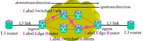
MPLS is a technology to forward the packets in IP un- aware networks. Entire MPLS network can be divided into two parts namely MPLS edge and MPLS core [4]. MPLS edge is the boundary of the MPLS network con- sisting of ingress and egress routers shown in Figure 1. MPLS core encompasses intermediate Label Switching Routers (LSRs), through which Label Switched Paths (LSPs) are formed. General terms associated with MPLS network and their meaning is specified below:
[image:2.595.56.290.651.719.2]1) Label Switching Router (LSR): LSR is a type of MPLS router which operates at the boundary and core of the MPLS network. Ingress and egress router are the two types of edge LSR. The ingress router attaches a new label to every incoming packet and forwards it into
Figure 1. MPLS domain network.
MPLS core. On the other hand, the egress router removes the attached label from the incoming MPLS packet and forwards it further to destination;
2) Label Switched Path (LSP): It is a route established between two edge LSRs which act as a path for forward- ing labeled packets over LSPs;
3) Label Distribution Protocol (LDP): It is a protocol used by the routers to create a label database. RSVP (Resource Reservation Protocol) and CR-LDP (Con- straint-based Routed Label Distribution Protocol) are some type of LDPs.
The MPLS operation is clearly shown in Figure 2. Ini- tially each of the MPLS routers creates a table. LDP uses the routing table information to establish label values among neighboring LSRs and created LSPs. As soon as a packet arrives at ingress router, it assesses the QoS and bandwidth requirements of the packet and assigns a suit- able label to the packet and forwards it into MPLS core. The labeled packet is transmitted over several LSRs in- side the MPLS core till it reaches the egress router. Egress router takes off the label and reads the packet header and forwards it to appropriate destination node.
4. Traffic Engineering and Signal Protocols
Traffic Engineering is the process of selecting network paths so the traffic patterns can be balanced across the various route choices. The use of LSPs in MPLS can help balance the traffic on network link event [3]. It allows a network administrator to make the path deterministic and bypass the normal routed hop-by-hop paths. An adminis- trator may elect to explicitly define the path between stations to ensure QoS or have the traffic follow a speci- fied path to reduce traffic loading across certain hops. In other words, the network administrator can reduce con- gestion by forcing the frame to travel around the over- loaded segments. Traffic engineering, then, enables an administrator to define a policy for forwarding frames rather than depending upon dynamic routing protocols, traffic engineering is similar to source-routing in that an explicit path is defined for the frame to travel, however, unlike source-routing, the hop-by-hop definition is not carried with every frame [11].
Signaling is a way in which routers exchange relevant information. In an MPLS network, the type of informa- tion exchanged between routers depends on the signaling protocol being used. At a base level, labels must be dis-
[image:2.595.314.537.654.720.2]tributed to all MPLS enabled routers that are expected to forward data for a specific FEC (Forwarding Equivalent Class) and LSPs created. The MPLS architecture does not assume any single signaling protocol. The power of MPLS depends on its TE capabilities and the efficiency of control plane i.e. routing and signaling. The routing protocols are basically reused from the IP system. Con- sequently, the design of signaling protocols is something that brings new functionalities and thus is very important for general operation as well as for TE. In this way Con- straint based routed Label Switched Path CR-LSPs are used for TE in MPLS [10]. Two protocols are used to set CR-LSPs in MPLS that are:
Constraint based routed LDP (CR-LDP); Resource Reservation Protocol (RSVP-TE).
4.1. Constraint Based Routed LDP (CR-LDP)
CR-LDP is an extension of LDP to support constraint based routed LSPs. The term constraint implies that in a network and for each set of nodes there exists a set of constraint that must be satisfied for the link or links between two nodes to be chosen for an LSP [13]. CR- LDP is capable of establishing both strict and loose path setups with setup and holding priority, path Preemption, and path re-optimization [6]. CR-LDP and LDP proto- cols are hard state protocols that means the signaling message are sent only once, and don’t require periodic refreshing of information. In CR-LDP approach, UDP is used for peer discovery and TCP is used for session advertisement, notification and LDP messages. CR-LSPs in the CR-LDP based MPLS network are set by using Label Request message. The Label Request message is the signaling message which contains the information of the list of nodes that are along the constraint-based route. In the process of establishing the CR-LSP the Label Request message is sent along the constraint-based route towards the destination.
If the route meet the requirements given by network operator or network administrator, all the nodes present in route distribute the labels by means of Label Mapping message. Figure 3 summarizes the CR-LDP signal pro- tocol operation.
4.2. Resource Reservation Protocol (RSVP-TE)
RSVP-TE is an extension of RSVP that utilizes the RSVP mechanisms to establish LSPs, distribute labels and perform other label-related duties that satisfies the requirements of TE [12]. The revised RSVP protocol has been proposed to support both strict and loose explicit routed LSPs (ERLSP). For the loose segment in the ER-LSP, the hop-by hop routing can be employed to determine where to send the PATH message [13].
RSVP is a soft state protocol. It uses Path and RSVP
commands to establish path.
The CR-LSPs established by RSVP signaling protocol in MPLS network is described by the following steps: The Ingress router in the MPLS network selects a
LSP and sends the Path message to every LSR along that LSP, describing that this is the desired LSP used to establish as CR-LSP.
The LSRs along the selected LSP reserve the re- sources and that information is send to Ingress router using the RSVP message.
[image:3.595.359.489.463.616.2] In this process the Path and RSVP messages are send periodically to refresh the state maintained in all LSRs along the CR-LSP [7].
Figure 4 summarizes the RSVP signal protocol ope- ration.
5. Simulation
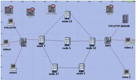
The simulation environment employed in this paper is based on OPNET 14.5 simulator which is an extensive and powerful simulation software. In this part of the simulation the VoIP traffic is sent between work station (voice 1) and work station (voice 2), the same termina- logy is followed with video traffic which is sent between work station (video 1) and work station (video 2). FTP and HTTP traffic is sent between work station (FTP, HTTP) and (FTP, HTTP server). Internet Core consists of six routers and two switches. These routers are con- nected with DS3 cable data rate 44.736 Mbit/s. The end nodes are connected to switch and switch and internet core routers with 100BASET cable.
UDP Hello UDP Hello TCP Open Initialization(s) Label Request Label Mapping
[image:3.595.345.503.645.717.2]Figure 3. CR-LDP signal protocol operation.
Figure 4. RSVP signal protocol operation.
301
5.1. Simulation Parameters protocols (CR-LDP and RSVP-TE) are implemented. As shown in Figures 5 and 6 respectively.
The simulations were set up using a normal IP network without Traffic engineering and an MPLS network with Traffic Engineering (composed of with MPLS signaling
[image:4.595.80.515.146.402.2]Pulse-Code-Modulation (PCM) with a coding rate of 64 kbps is used by the voice workstations which set up to
[image:4.595.84.515.426.718.2]Figure 5. IP network topology.
transfer one frame per packet. Video workstations trans- fer 10 frames per second, each frame consists of 128*120 pixels. HTTP work stations used pages of size 1000 bytes, while FTP work stations used files of size 5000 byte. Simulation time for all workstation is 280 seconds. The first VoIP and video call is created at the 10th se- cond of the simulation as this time will be used to train the network for the current environment then a call will be created for every 2 seconds, same as other applica- tions, FTP and HTTP, where requests are initiated every two seconds simultaneously. The process of call initia- tion and service request will be repeated until the end of the simulation period.
The voice delay can be divided in to three contributing components which are described as follows [8,9]: The delay introduced by the G.711 codec for encod-
ing and packetization are 1 ms and 20 ms respectively. The delay at the sender considering above two delays along with compression is approximated to a fixed delay of 25 ms;
At the receiver the delay introduced is from buffering, decompression, depacketization and playback delay. The total delay due to the above factors is approxi- mated to a fixed delay of 45 ms.
The overall network delay can be calculated from the above sender and receiver delays to be 80 ms approxi- mately (150-25-45). Where 150 ms represents the maxi- mum acceptable end-to-end delay so that the quality of the established VoIP call is acceptable [8].
Then the maintained nu Threshold time startin
mber of calls
g time 2 (1)
Threshold time: is the time during the simulation when the end-to-end delay exceeds the network delay 80 ms.
5.2. Simulation Results
In the IP network shown in Figure 5 the traffic uses some paths for sending packets even if they carry heavy traffic and ignores the other paths even if they carry light traffic. This might lead to congestion. The packet trans- ferred through the IP routers takes time to arrive at des- tination because the routing table of routers is complex. MPLS networks solve the first problem by employing TE protocols to determine the best path. The second problem is solved by MPLS as well by replacing IP routing by label switching.
RSVP TE signal sets the path at the beginning of simulation time, but the problem is that it periodically sends a refresh message to each LSR, which introduces additional delay (soft-state). CR-LDP TE signal protocol does not incur such additional delay (hard-state); instead it only uses label request messages to transfer packets between two LSRs.
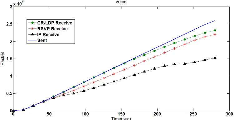
[image:5.595.111.486.512.705.2]Figure 7 shows the average number of transmitted and received voice packets versus simulation time. We can see that IP network starts dropping packets at time 30 s of the simulation while the MPLS network with RSVP TE signal protocol starts dropping voice packets at 38 s. The best performance is shown by the MPLS network with CR-LDP TE signal protocol which starts dropping voice packets at 128 s as shown in Figure 8. Based on Equation (1), the number of maintained calls for the three scenarios is 10, 14 and 59 calls respectively.
Figure 9 shows the average number of transmitted and received video packets, of a video conference session between work stations video 1 and video 2, versus simulation time. We can see that IP network starts dropping packets at time 28 s of the simulation while the MPLS network with RSVP TE signal protocol starts
Figure 7. Average number of send and receive voice packets for MPLS networks with (CR-LDP, RSVP) TE signal protocols and IP network.
303
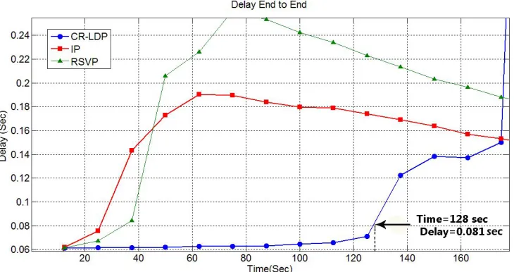
[image:6.595.110.489.308.504.2]Figure 8. Voice packets end to end delay in MPLS network with (CR-LDP, RSVP) TE signal protocols and IP network.
Figure 9. Average number of send and receive video packets in MPLS networks with (CR-LDP, RSVP) TE signal protocols and IP network.
dropping voice packets at 36 s. The performance of these two networks is outperformed by the MPLS network with CR-LDP TE signal protocol which starts dropping video packets at 64 s. Based on equation one, the number of maintained video calls for the three scenarios is 10, 15 and 30 calls respectively.
Figure 10 Shows the average number of transmitted and received FTP packets versus simulation time when the work station (FTP) sends packets to the FTP server with 2 seconds packets spacing. As shown in the figure the performance of the MPLS network with RSVP TE protocol is better than that of the IP network, whilst the MPLS network with CR-LDP TE protocol is the best.
Figure 11 shows the average number of transmitted and received HTTP packets versus simulation time when the work station (HTTP) communicates with the HTTP
server. The MPLS network with RSVP protocol is better than IP networks, while the MPLS network with CR- LDP protocol outperforms both networks.
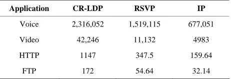
Table 1 Summarizes the average sum of received packets in MPLS network with (CR-LDP, RSVP) TE sig- nal protocols and IP network.
6. Conclusions
Figure 10. Average number of sent and receive FTP packets in MPLS network with (CR-LDP, RSVP) TE signal protocols and IP network.
[image:7.595.114.485.325.516.2]HTTP
Figure 11. Average number of sent and receive HTTP packets in MPLS network with (CR-LDP, RSVP) TE signal protocols and IP network.
Table 1. Average sum of received packets in the three net- works MPLS with CR-LDP, MPLS with RSVP and con- ventional IP.
Application CR-LDP RSVP IP
Voice 2,316,052 1,519,115 677,051
Video 42,246 11,132 4983
HTTP 1147 347.5 159.64
FTP 172 54.64 32.14
compared to that of a conventional IP networks in terms of resources usage and traffic congestion.
Further investigations show that the CR-LDP TE signal protocol has a noticeable performance advantage com-
pared to the RSVP TE signal protocol. This is mainly due to the poor scalability of RSVP protocol resulted from the extra traffic requirements for periodic refreshment of traffic, high LSP failure recovery traffic and RSVP mes-sages to maintain the states in all LSR. On the other hand, the CR-LDP protocol is more reliable protocol as it uses TCP to transport its signaling messages resulting in fast failure notification.
REFERENCES
[1] D. O. Awduche, A. Chiu, A. Elwalid, I. Widjaja and X. Xiao, “Overview and Principles of Internet Traffic Engi- neering,” Request for Comments (RFC) 3272, May 2002. www.ietf.org
[image:7.595.58.289.595.674.2]305
[2] E. Osborne and A. Simha, “Traffic Engineering with MPLS,” Cisco Press, Morrison, 2002.
[3] S. Kasera, “ATM Networks Concepts and Protocols,” Tata McGraw-Hill Education, Noida, 2006.
[4] U. Black, “MPLS and Label Switching Network,” 2nd Edition, Prentice Hall, London, 2002.
[5] E. Rosen, A. Viswanathan and R. Callon, “Multiprotocol Label Switching Architecture,” RFC 3031, Janaury 2001. www.ietf.org
[6] M. Kr. Porwal, A. Yadav and S. V. Charhate, “Traffic Analysis of MPLS and Non-MPLS Network Including MPLS Signaling Protocols and Traffic Distribution in OSPF and MPLS,” LAP LAMBERT Academic Publish- ing, Saarbrücken, 2008.
[7] N. F. Mir and A. Chien, “Simulation of Voice over MPLS Communications Networks,” IEEE Computer Society, Washington DC, 2002, pp. 389-393.
[8] K. Salah and A. Alkhoraidly, “An Opnet-Based Simula-
tion Approach for Deploying VoIP,” International Jour- nal of Network Management, Vol. 16, No. 3, 2006, pp. 159-183.
[9] R. S. Naoum and M. Maswady, “Performance Evaluation for VOIP over IP and MPLS,” World of Computer Sci- ence and Information Technology Journal (WCSIT), Vol. 2, No. 3, 2012, pp. 110-114.
[10] A. Ghanwani, “Traffic Engineering Standards in IP Net- works Using MPLS,” IEEE Communications Magazine, Vol. 37, No. 12, 1999, pp. 49-53.
doi:10.1109/35.809384
[11] R. J. Bates, “Broadband Telecommunications Handbook,” 2nd Edition, McGraw-Hill Companies, New York, 2002.
[12] B. Jamoussi, et al., “Constraint-Based LSP Setup Using LDP,” IETF RFC 3212, Janaury 2002. www.ietf.org