Abstract - This paper describes the idea of application of active suspension system in hybrid electric vehicles (HEVs). For the investigation of this idea, a methodological approach for simultaneous simulation of power train and suspension systems is presented. In this approach, the hybrid electric power train and the active suspension systems simulations are integrated and the exchange of power and data between two systems is simulated.
Considering the effect of power train simulation input, introduced as driving cycle on the suspension disturbance, two combined road-speed disturbances are generated and are applied to the suspension system. Furthermore, energy interaction of the AS and power train systems is modeled for both conventional and hybrid electric power trains. The simulation results show the ability of the approach for investigation of the active suspension system power demand as well as fuel consumption, emission, and the ride characteristics of the hybrid electric vehicle equipped with active suspension system.
Keywords: Active Suspension- Hybrid Electric, Vehicle- Simultaneous Simulation
I. Introduction
Vehicle suspension system is responsible for driving comfort and safety as the suspension carries the vehicle body and transmits all forces between body and road [1]. In order to positively influence these properties, active components are introduced. Active components enable the suspension system to adapt to various driving conditions. By adding a feedback controlled actuator, driving comfort and safety are considerably improved compared to suspension setups with fixed properties [2]. Although auto industry has witnessed considerable advancements in active suspension (AS) system technology in recent years, the main barrier ahead of widespread application of this system in conventional vehicles is its high energy demand and cost. In addition, application of AS system in conventional vehicles encounters some problems that may affect its performance.
In conventional vehicles, the power required for the active suspension system is powered by the vehicle’s engine. Due to its dynamics, the internal combustion engine (ICE) requires time to adjust to the time-varying loads imposed by AS. If these loads vary faster than the engine can adjust, then the Seyedmohsen Hosseini is with the Faculty of Engineering, Kingston University. (Email: [email protected])
Rushed Abdolah is with Bradford University. (Email: [email protected])
Amir Khani is with University of Tehran, Tehran. (Email:
suspension will, temporary, not function properly while the vehicle itself may hesitate. If, on the other hand, the load gets reduced too fast, vehicle surge may occur [3]. Besides, AS loads may shift the engine operating points to inefficient regions and increase its instant emissions and fuel consumption.
Hybrid Electric Vehicles (HEVs), on the other hand, are projected as one of the solutions to the world’s need for cleaner and more fuel-efficient vehicles. HEVs employ two (ore more) energy storage sources and the associated energy converters to generate the power required to drive the vehicle and to operate on-board accessories. Most typically, the architecture of these vehicles includes an internal combustion engine with an associated fuel tank and an electric machine with its associated battery (energy storage) system. In the HEVs, unlike the conventional vehicles, the sub systems may be powered by either mechanical combustion engine or the electrical power bus sources. This can be especially helpful when one of the power sources can’t provide the load due to its performance constraint.
In this paper, the idea of application of AS suspension system in HEVs is introduced. The motivation of this study is the possible advantages of this application over the conventional one. For this study, the modeling, simulation, and control of the active suspension system and the hybrid electric power train are firstly described separately. Simulation of the AS is performed based on a seven DOF model associated with pseudo skyhook control approach. In addition HEV simulation is presented using a fuzzy control scheme. An approach for the simultaneous simulation of two systems is then proposed and the application of AS in HEVs is investigated.
In the first stage and as a preliminary goal, providing a simulation tool in which the suspension and power train systems are simulated simultaneously is considered. In the simulation media, the data and energy exchange between two systems is modeled. The problem of time step for the coherent simulation of two systems is discussed. In addition, combination of the road irregularities and the vehicle speed pattern imposed by the driving cycle is considered. Moreover, computer simulations are conducted and systems simultaneous simulation results are studied. AS system power
consumptions in both bumpy and random terrains are calculated considering vehicle speed patterns. Furthermore, the ICE performance in either conventional and hybrid electric power train systems is examined while it is experiencing AS system loads. Besides, the conventional and the hybrid electric vehicles fuel consumption and emission results with and without AS loads are compared.
Investigation of the Idea of Active Suspension System
Application in Hybrid Electric Vehicles
II. Active Suspension Modeling and Simulation
The regular seven degree of freedom model (Fig. 1) is used for the suspension system simulation. This model is a proper choice for ride quality study as it captures the effective degrees of freedom employed in the ride quality evaluation, according to ISO 2631 standard criteria i.e. body bounce, pitch and roll accelerations. It is assumed that body and wheel
[image:2.612.79.298.181.374.2]displacements are measured from their static equilibrium position. Tire-road holding force is also estimated as a nonlinear function using the following equation:
Figure 1: Suspension system seven DOF model.
Fholding = kt(xu-x0) if (xu-x0)
≤
Δ
stat Fholding = 0 if (xu-x0)≥
Δ
statThe suspension spring stiffness in the active model has been decreased up to half of its original value in the passive model. Suspension dampers in the active model are also replaced with active actuators.
III. Active Suspension Control
In the active suspension system, a feedback controlled actuator is used to improve the driving comfort and safety. The active components enable the suspension system to adapt to various driving conditions. Trade off between the ride comfort and the vehicle stability has been driving force for advancements in automotive suspensions [2, 4 and 5]. One of the main objectives of the active suspension design in this work is to improve ride quality. The other objective is to keep the tire load within an acceptable limit.
For control force calculation in this study, the well known skyhook control strategy patented by Karnop [6] is employed. We call this force ‘quasi-skyhook force’ to distinguish the difference between a real skyhook suspension and the active suspension system considered in this work. As the name implies, the skyhook configuration has a damper connected to some inertial reference in the sky, as shown in Figure 2. Using a skyhook configuration, the tradeoff between resonance control and high-frequency isolation, common in passive suspensions, is eliminated [7].
[image:2.612.335.514.255.677.2]In order to expand the skyhook control law to the seven DOF model, it is assumed that the body is suspended at its corners by skyhook dampers. Considering this scenario, the seven DOF model has been divided to four separate quarter models (Figure 3). The logic behind this control design is that, by reducing the transmitted force from suspension system to the body at its corners, the total transmitted force to the body is reduced.
This reduction, consequently, will result in reduction of body bounce, pitch and roll accelerations. Considering this inference, the body motion is controlled at its corners using the skyhook strategy where the active suspension actuators forces have been calculated at the body four corners. Comparing the equations of motion of the skyhook model and the suspension quarter model (Equation 2 and Equation 3), the active suspension actuator force can be estimated using equation 4.
[image:2.612.350.519.266.460.2]Figure 2: Skyhook model
..
s
x
=1
[
(
)
(
)
]
. .
F
x
x
C
x
x
k
M
s s s−
u+
s s−
u+
−
(2)]
)
(
)
(
[
1
. ...
F
x
x
C
x
x
k
M
x
u s u s s uu
u
=
−
+
−
+
)]
(
)
(
[
1
. .. s skyhook u s s ss
k
x
x
C
x
M
x
=
−
−
+
(3))]
(
)
(
)
(
[
1
. 0 . 0 ..x
x
C
x
x
k
x
x
K
M
x
s s u t u t uu
u
=
−
−
−
−
−
s skyhook
x
C
F
..
−
=
(4)IV. HEV Power Train Simulation
In this section, the power train simulation is presented to obtain an acceptable estimation for the fuel consumption and exhaust emissions of conventional and hybrid electric vehicles. The power train simulation method used in this study incorporates a backward-facing approach [8]. Backward-facing approach is shown in Figure 4 as a schematic diagram. This approach does not require any model for driver behavior. Instead, a driving cycle is traced by the vehicle. Vehicle required traction force and velocity are then translated into the required torque and velocity that must be provided by the vehicle wheel and other components upstream. This calculation approach carries backward through the driveline against the tractive power flow direction until the fuel use and/or the electrical energy use that would be necessary to meet the trace is computed. Backward approach is greatly dependent on the internal combustion engine (ICE)
[image:3.612.70.298.474.586.2]specific fuel consumption (SFC) and emissions maps.
Figure 4: Backward facing simulation schematic The parallel configuration of the HEV has been considered for this study. In addition, ADVISOR (Advanced Vehicle Simulator) is employed for the backward simulation of both conventional and HEV. However, the kernel of the HEV modeling and simulation is the control design discussed in the next section.
V. HEV Power Train Control Design
A parallel HEV incorporates two power drives including ICE and electric motor (EM). Therefore, it is the responsibility of the parallel HEV control strategy to determine how to distribute the driver’s required torque between the ICE and EM. The HEV control strategy is aimed at several simultaneous targets such as minimization of the fuel consumption (FC) and exhaust emissions (HC, CO and NOx). Unfortunately, these aims are often in conflict with each other i.e. the minimum fuel consumption does not necessarily result
in the minimum emissions, implying the need for a trade off solution.
The bottom line for control strategy is that the vehicle must follow the driver’s request. This means that the total torque delivered by the ICE and EM must be determined such that the driver’s torque requests (from brake and accelerating pedals) are satisfied consistently.
The driver request is equivalent to the driving cycle. Therefore, control strategy must perform such that the driving cycle is tracked adequately. Another aim for control strategy is to maintain or enhance vehicle performances like grade ability, acceleration, etc. In this study, PNGV passenger car constraints [9] are used to ensure that the vehicle performance is not sacrificed during the trade off solution. One of the other
constraints for control strategy are remaining charge-sustained.
This constraint has been introduced to force the battery SOC to recover its initial value at the end of the driving cycle. In this work, the difference between final SOC and initial SOC is forced not to exceed 0.5% of the initial SOC.
Fuzzy control approach is employed to devise HEV control design in this study. The main objective of the fuzzy controller is to cause the ICE to work in the vicinity of its optimal operating points. The optimal operating points of the engine are determined based on ICE parameters at the current vehicle speed to minimize instantaneous fuel consumption and emissions. At any particular point in time, the speed of rotation for the ICE is determined based on the power train configuration and the current gear ratio. This is the speed at which the instantaneous optimization is performed. For the current speed, all possible torques that the ICE can provide are considered. Then the fuel consumption (FC) and emissions (HC, CO and NOx) for all torques at the current speed are taken from the engine maps and the following cost function is calculated for all of these points:
(5)
Figure 5: Optimum engine torques
[image:4.612.74.297.333.430.2]Figure 6 depicts the fuzzy controller schematic diagram. As it can be seen, the controller inputs are required tractive torque and batteries state of the charge. The controller output is also EM torque determined based on the controller inputs and rule base.
Figure 6: Hybrid Power train Control Strategy
The rule base is defined by a set of 9 rules, as listed in table 1. The general logic behind these rules is the idea of load leveling, in which the EM is used to assist or generate, while it is running the ICE near optimal operating point. In fact the optimal operating point of the ICE is varied based on SOC constraints. For instance, consider a case (the last rule in rule table) when the required torque is above the optimal operating point. Let us assume that the SOC is high. We would like to bring the ICE operating point near the optimal operating point
(for that speed). This would mean a lower torque output by the ICE than what is required to meet the driver’s demand. This requires that the EM to be run as a motor to make up for the remaining torque provided that there is enough battery charge. Since we do have sufficient charge in this case, the ICE is allowed to operate near the optimal operating point.
Table 1 FLC Rule Base
VI. Simultaneous Simulation of HEV Power Train and Active Suspension Systems
Vehicle power train and active suspension systems are studied in a novel coherent simulation approach. In this approach, the vehicle power train simulation is integrated with the active suspension simulation as shown in Figure 7. In this figure, data and energy flows are shown. Using this approach, power train emissions and fuel consumption as well as the vehicle dynamic characteristics including the ride comfort parameters and the tire-road holding force is calculated simultaneously. Figure 7 shows the schematic diagram of this approach.
Figure 7: Schematic diagram of simultaneous simulation of power train and active suspension systems.
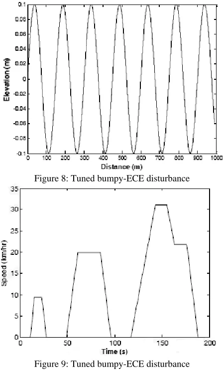
[image:4.612.308.543.336.522.2]bumpy road. In this case, the ICE engine is started in the cold condition and the emission sampling is started immediately after the engine startup. In the second simulation setup named Rand-Const, the vehicle traces a constant 96.56 km/hr speed while it passes over a smooth random road. In this case, the IC engine is started in the hot condition and the emission sampling is started after engine is reached the steady condition.
[image:5.612.72.296.178.551.2]Figures 8, 9, and 10 show the ECE driving cycle, bumpy road, and the combined bumpy-ECE road disturbances, respectively.
Figure 8: Tuned bumpy-ECE disturbance
Figure 9: Tuned bumpy-ECE disturbance
Figure 10: Tuned bumpy-ECE disturbance
In addition, the suspension and the power train are two systems with different dynamics. Power train dynamics, in a backward–facing approach, is mostly based on a slow dynamics using the lookup tables represented mostly by algebraic equations while the suspension dynamics is introduced by much faster differential equations. The acceptable numerical time step is therefore crucial in the simultaneous simulation of these two systems. In order to tackle this problem, the power train system time step has been fined up to an acceptable active suspension time step level. Furthermore, the active suspension and power train systems have interaction in term of energy. The active suspension required power is demanded from the power train system continuously. In the conventional vehicles, this power load is imposed on the ICE while in the HEVs it may be demanded form the electric power bus. In this study, energy interaction of AS system with conventional and hybrid electric power trains has been considered separately. In the conventional vehicle, the active suspension load (Equation 6), is modeled as an extra torque added up to the engine required torque. In the hybrid electric vehicle, on the other hand, this load is considered as an additional electrical accessories load requested from the electrical power bus.
)
.(
.
.
act skyhook s s uact
act
F
V
C
V
V
V
P
=
=
−
−
(6)VII. Simulation Study and Results Analysis
The advanced vehicle simulator (ADVISOR) [8] and MATLAB-SIMULINK are used for simulation study. Simulations are performed for both conventional and hybrid electric vehicles. Using two power train configurations and two suspension options, four possible combinations of the power train and suspension systems i.e. hybrid electric or conventional vehicles with active or passive suspensions have been considered for simulation. Performing computer simulations, the vehicle dynamic responses as well as the power train emission and fuel consumption have been extracted. In addition, the body bounce and pitch accelerations as well as the tire road holding force are computed by simulation. Furthermore, the impact of active suspension load on the combustion engine as well as the energy storage system has been examined. Figure 11 depicts the random road disturbance. In addition, Figures 12, 13, and 14 show the body bounce acceleration, suspension travel, and tire-road holding force respectively.
Figure 12: Body bounce acceleration
[image:6.612.68.538.43.616.2]Figure 13: Suspension travel
Figure 14: Tire holding force
These results show that, using the pseudo-skyhook active suspension system, a considerable decrease in body accelerations is occurred. This confirms the devised AS system capability in improving the ride quality.
1: Conventional, random+ constant 2: Conventional, bumpy+ ECE 3: HEV, random+ constant 4: HEV, bumpy+ ECE
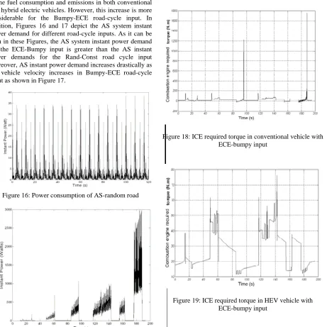
of the fuel consumption and emissions in both conventional and hybrid electric vehicles. However, this increase is more considerable for the Bumpy-ECE road-cycle input. In addition, Figures 16 and 17 depict the AS system instant power demand for different road-cycle inputs. As it can be seen in these Figures, the AS system instant power demand for the ECE-Bumpy input is greater than the AS instant power demands for the Rand-Const road cycle input Moreover, AS instant power demand increases drastically as the vehicle velocity increases in Bumpy-ECE road-cycle input as shown in Figure 17.
Figure 16: Power consumption of AS-random road
Figure 17: Power consumption of AS-bumpy-ECE Furthermore, Figures 18 and 19 show the ICE required torques for both the conventional and hybrid electric vehicles where an ECE-bumpy input is applied. As it can be seen in these Figures, the instant torque imposed on the ICE by AS system is quite large at some specific conditions in the conventional vehicle. In this case, the ICE operation will result in a more fuel consumption and emissions. In addition, the engine might not be able to provide the required torque at some specific points that may affect the performance of the AS system. However, using an HEV configuration, the instant
[image:7.612.85.546.50.511.2]torque imposed on the ICE by the AS system is reduced considerably, leading to more efficient condition. The required torque is also within the ICE maximum torque limit, providing the necessary AS system power at all instant conditions.
Figure 18: ICE required torque in conventional vehicle with ECE-bumpy input
Figure 19: ICE required torque in HEV vehicle with ECE-bumpy input
VIII. Conclusions
In this paper, a methodological approach is presented for investigation of the idea of the application of active suspension system in hybrid electric vehicles.
In this approach, the active suspension and power train simulations are integrated and a simultaneous simulation tool is developed for energy study. Four configurations including the conventional and hybrid electric vehicles as well as the ECE-bumpy and Constant-random inputs are considered. The
[image:7.612.317.533.62.219.2]References
[1] Reimpell, J. and Stoll, H., 1996, The Automotive Chassis: Engineering Principles.
[2] Fischer, D., Isermann, R., 2004, "Mechatronic semi-active and active vehicle suspensions", Control Engineering Practice, 12, 1353-1367.
[3] Mrad, R. B., Fassois, S. D., and Levitt, L. A., 1998 "A Polyniminal-algebric method for nonstationary TARMA signals analysis- Part II: Application to modeling and predicting power consumption in automobile active suspension systems", Signal Processing, 65, 21-38.
[4] Goncalves, F. D., 2001 "Dynamic Analysis of Semi-Active Control Techniques for Vehicle Applications", M.S.C Dissertation, Virginia Polytechnic Institute and State University.
[5] Mounir, M., Kamal, M., Wolf, Jr., and Joseph, A., 1982, Modern Structural Analysis, New York. Van Nostrand Reinhold Company.
[6] Karnopp, D., Crosby, M. J., 1974, "System for Controlling the Transmission of Energy Between Spaced Members". United States Patent #3,807,678.
[7] Yi, K., Hedrick, K., 1993, "Dynamic Tire Force Control by Semiactive Suspensions", Journal of Dynamic Systems, Measurements, and Control, 115, 465-474.
[8] Wipke, K. B., Cuddy, M. R., and Burch, S. D., 1999, " ADVISOR 2.1: a user-friendly advanced Power train simulation using a combined backward/forward approach", IEEE Trans. Vehicular Technology, 48 (6), 1751–1761. [9] Moore, T.C. and Lovins, A.B., 1995, "Vehicle design strategies to meet and exceed PNGV goals", Electric and Hybrid Vehicles— Implementation of Technology SAE Special Publication SP-1105, 79–121.