Abstract— Multimedia communication over wireless networks has become the driving technology for many important applications, experiencing dramatic market growth and promising revolutionary experiences in personal communication, gaming, entertainment, military, security, environment monitoring, and more. The advances in wireless communications and growth of real-time applications have necessitated the development of wireless networks that can support high Quality of Service (QoS) and power control. A node in an ad hoc network is normally battery operated which poses a huge constraint on the power consumption of such a node. Hence, designing a power efficient MAC protocol for ad hoc wireless networks is a major challenge. In this paper, we propose a reservation based, asynchronous MAC protocol called Multi-rate Multi-hop MAC Protocol (MMMP) with power control for multi-hop ad hoc networks. The protocol conserves power and provides QoS guarantees for
multimedia traffic. MMMP with power control achieves this by having every node maintain two reservation tables to keep track of ongoing transmissions. It calculates the appropriate transmission power (i.e the power level high enough to reach the destination node rather than transmitting at maximum power) based on node distances, which results in energy savings without causing throughput degradation. Simulation results obtained using the C programming language indicate that MMMP-Power Control outperforms IEEE 802.11 in all performance metrics and can efficiently handle a large range of traffic intensity. It also outperforms other similar state of the art MAC protocols.
Index Terms—WLAN, 802.11, QoS, Multimedia.
I. INTRODUCTION
In recent years wireless communication networks have become increasingly popular. Many types of wireless services have become available, including cellular systems, satellite communication networks, and wireless local area networks (WLANs) [1, 2]. The increasing popularity of WLANs and wireless devices has led to greater interest in wireless ad hoc networks. An ad hoc network [3] is formed by wireless, potentially mobile hosts, without requiring the use of any fixed infrastructure, and can be set up in the environment where the wiring of a conventional network is difficult or not economically feasible. Wireless ad hoc networks face challenges that are not present in wired networks. In wired networks, transmission errors typically occur at a low rate and interference among different
Mahasweta Sarkar is an Assistant Professor at the Electrical and Computer Engineering department at San Diego State University, San Diego, CA 92182, USA. (e-mail: [email protected]).
Sahitya Borra is a graduate student in the Computer Science Department at San Diego State University, San Diego, CA 92182, USA (e-mail: sahityaborra@ gmail.com).
communication flows is minimal. Collision detection is usually fast and easy in wired networks. Wireless communication, however, requires a shared transmission medium that is highly error-prone. Hence, in wireless communication, there is a much higher chance for collisions to occur. It is also more difficult to detect a collision in a wireless network. Often the lack of a reply message is the only way for a node to detect a collision. Therefore, compared to a wired network, a wireless network requires a different and more complicated medium access control (MAC) layer. This paper focuses on the issues on MAC layer for wireless networks.
The rest of this paper is organized as follows: Section II discusses the basics of video compression and the 802.11 protocol stack respectively. Section III outlines the video QoS enhancing algorithm. Section IV discusses the simulation set up. Section V enumerates and analyses the simulation results. Finally, we conclude the paper in Section VI.
II. RELATED WORK
A. MACA Protocol
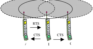
Multiple Access with Collision Avoidance (MACA) [4] was proposed as an improvement over CSMA for packet radio networks to eliminate the hidden terminal problem. MACA protocol introduces a handshake between a sender and receiver, as illustrated in Figure.1, to ensure that neighboring nodes are aware of the upcoming transmission, and refrain from sending for this duration. A Request to Send (RTS)
signal is transmitted by the sender to the receiver to initiate the handshake and indicate its request to access the medium. The sender to notify the neighboring node of the upcoming transmission also uses this RTS message. On receiving an RTS, the receiver responds with a Clear to Send (CTS) message to indicate its readiness for reception and also to notify the nodes in its vicinity of the transmission. Once the RTS/CTS handshake is complete, the transmission proceeds
A QoS Enabled MAC Protocol for Wireless Ad
hoc Networks with Power Control
Mahasweta Sarkar and Sahitya Borra Member, IEEE
[image:1.595.326.522.547.651.2]A B C
Figure 1: MACA scheme – RTS/CTS Handshake
RTS
with no risk of collisions. In case there is a collision of two RTS messages, then both stations back off for some time. By reducing the possibility of collisions and eliminating the hidden terminal problem for data transmissions, MACA offers an improvement over CSMA.
[image:2.595.51.244.388.520.2]As illustrated in Figure 1, in a hidden terminal scenario node C will not hear the RTS sent by node A, but would hear the CTS sent by B and defer transmission accordingly. Similarly, in an exposed terminal scenario, node C would hear the RTS sent by B, but not the CTS sent by A and will consider itself free to transmit during node B’s transmission. The RTS-CTS approach, however, does not always solve the hidden terminal problem completely. When there are a number of nodes transmitting RTS and CTS packets, collisions can still occur. Consider the example shown in Figure 2. Here, node A sends an RTS packet to node B which then replies with a CTS packet back to node A. At node C, this CTS packet, however, collides with node D’s RTS packet. Node C is, therefore, unaware of the subsequent node A to node B data transmission. During the transmission between nodes A and B, node D sends another RTS to node C as it did not receive a CTS packet in its first attempt. Since node C is unaware of the transmission between nodes A and B, it replies with CTS to node D, which collides with the DATA packet at node B. Under conditions of high network traffic and the presence of hidden terminals, the MACA scheme has a poor performance.
Figure 2: Illustration of a case where RTS/CTS approach does not entirely resolve the hidden terminal problem [5].
The other weakness in MACA is that it does not provide for any acknowledgement of data transmissions at the data link layer. If a transmission fails for any reason, retransmission has to be initiated by the transport layer, causing significant delays in the transmission of data.
B. Power Control and Multi Channel
The power consumption of individual nodes and the overall network is a major design consideration for ad hoc network MAC protocols. The limited battery power of the mobile nodes makes power conservation very critical, whether they operate in an ad hoc or infrastructure network.
i) DCAPC
Dynamic channel assignment with power control (DCAPC) [6] was proposed to address both power and multi channel issues. DCAPC has one control and N data channels. In DCAPC a sender, before sending RTS, checks to see if there is a free data channel and if available, it selects an available channel and sends a RTS signal on the control channel to the
destination with maximum power. If the destination node is in agreement with the sender’s channel choice, it replies with CTS at a power level appropriate to reach the sender. The sender then reserves the channel. If the destination has a conflict with the sender’s channel choice, it sends its free channel list for the sender to choose a more appropriate channel. DCAPC also optimizes power consumption at the node during transmission, by controlling the transmit power so that it is just enough to reach the intended receiver. DCAPC specifies a detailed behavior of how each node continuously monitors, records, and updates the transmission power level it needs to reach each neighbor. At start, the nodes are not aware of the appropriate power levels and hence they transmit with maximum power. After establishing contact with neighbor nodes, the appropriate power levels for communication are calculated and noted by the nodes. However, it is observed that when the number of channels is increased beyond a point, the effect of power control is less significant.
ii) PAMAS
Power Aware Medium Access Control with Signaling (PAMAS) [7] takes advantage of a simple RTS/CTS handshake to overcome the problem of power wastage due to the overhearing of irrelevant transmission and idle listening. Similar to DCAPC, PAMAS also addresses both power and multi-channel issues. PAMAS protocol has two channels – a common control channel and a common data channel. PAMAS includes the length of the upcoming transmission in both RTS and CTS. If the nodes hear RTS or CTS on the control channel, they refrain from communicating since they are in the neighborhood of the sender and/or receiver. For the duration of the transmission, as indicated in the handshake messages, the neighboring nodes go into a sleep mode. Thus, PAMAS reduces power consumption for nodes operating in highly connected networks under sparse load conditions, where many idle nodes may be overhearing other nodes’ transmissions.
iii) DPSM
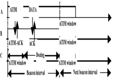
Figure 3: Power saving mechanism for DCF: Node A announces a buffered packet for B using an ATIM frame. Node B replies by sending an ATIM-ACK, and both A and B stay awake during the entire beacon interval. The actual data transmission from A to B is completed during the beacon interval. Since C does not have any packet to send or receive, it dozes after the ATIM window [5].
It has been shown [10] that for a fixed ATIM window size, performance suffers in terms of throughput and energy consumption. Therefore, in DPSM, the nodes choose the ATIM window size independently and dynamically, potentially resulting in varying window sizes for different nodes. In this scheme, once the packets are transmitted, the sender and receiver go into a sleep state and the nodes do not have to stay awake over the entire beacon interval (unlike in DCF). The ATIM window length is increased dynamically to ensure transmission of all queued packets in the outgoing buffer even after expiration of the current window. The ATIM window length information is piggybacked in data packets, and nodes that overhear may decide to modify their own window lengths based on this information. DPSM is seen to be more effective than IEEE 802.11 DCF in terms of power saving and throughput. Both IEEE 802.11 and DPSM are, however, not suitable for multi-hop ad hoc networks as they assume that the clocks of the nodes are synchronized and the network is connected.
iv) PCM
Power control enhancements to the IEEE 802.11 MAC protocol have been proposed by a few different schemes [11, 12]. These schemes specify that the RTS and CTS transmissions must be at maximum power to make the neighbors aware of the upcoming transmission, while the sender can subsequently transmit data at a lower power level in direct relation to the spacing between the node pair. This approach may, however, produce asynchronous links and result in collisions in the carrier sensing zone of the sender. To overcome this, Power Control Medium Access Control (PCM) [8] was proposed. In PCM, the sender and receiver periodically raise the power level during data transmission to keep the overhearing nodes aware of the ongoing transmission. PCM also stipulates that the source node periodically transmit DATA packet at maximum power level, for a short duration to enable nodes in the carrier sensing range to sense the signal. Thus, PCM achieves energy savings without causing throughput degradation. The operation of the PCM scheme requires a rather accurate estimation of received packet signal strength. Therefore, the dynamics of wireless signal propagation due to fading and shadowing effect may degrade its performance. Another
drawback of this scheme is the difficulty in implementing frequent changes in the transmit power levels.
III. THE PROTOCOL
The proposed protocol is called QoS-aware MAC protocol with power control (MPPC) for ad hoc networks is a combination of the scheme - Modified MACA/PR and an idea of distance based power control. Modified MACA/PR (MMACA/PR) scheme enables bounded end-to-end delay for real-time flows and is, thus, the basic structure of our scheme. For this we implement a power control mechanism that regulates the transmission power that a transmitting node uses. The appropriate transmission power is calculated based on the distance at which the recipient node is located the initial request to set up a connection is made by the transmitter at the maximum power level by sending a RTS packet to the receiver. The receiver then calculates the appropriate power level that is sufficient to carry out the communication between the two nodes legibly and includes this information in the CTS packet that it transmits to the transmitter in response to the RTS. Henceforth, the transmitter sets its transmission power at the desired level (as indicated in the CTS) and all communication thereafter is carried out at that power level.
MMACA/PR, originally proposed by Ying et al. [13], is the basic MAC protocol used in the proposed scheme, MPPC. All the nodes in the network maintain two reservation tables: Receive Reservation Table (RT) — Keeps track of the sessions in which the neighboring nodes are scheduled to receive timestamp and the power level in which they are transmitting.
Transmit Reservation Table (TT) — Keeps track of the sessions in which the neighboring nodes are scheduled to transmit timestamp and the power level in which they are transmitting.
Before transmitting RTS, the sender checks its two reservation tables – TT and RT – for an empty session big enough to transmit RTS/CTS/DATA/ACK. If an empty session is available, it will send a RTS packet at the maximum power level and wait for a CTS packet. On receiving the RTS packet, the receiver checks its two reservation tables and then calculates the appropriate power level based on the distance factor, that is sufficient to carry out the communication between the two nodes and includes this information in the CTS packet and transmits back to the sender if it is in a session that can accommodate
CTS/DATA/ACK transmissions. If the source does not receive CTS it will back off for a while and retransmit RTS. If the RTS/CTS handshake is successful, the transmitter sets its transmission power at the desired level (as indicated in the CTS) and sends the DATA packet. On receiving the DATA packet, the receiver sends back the ACK with the same power level. Every entry in the Reservation table used in MPPC has source, destination, and start time of the transmission, end time of the transmission, Flow ID, and power being used to transmit.
Where K is a constant and d is the distance between the nodes. So we have the following relationship for a given d: Pr = Pt × Constant.
IV. SIMULATION SET-UP
The MPPC protocol has been implemented using the C programming language. We considered various topologies during our simulation. The results depicted here were based on a network comprising of different loads (active nodes). Traffic comprises of constant bit rate (CBR) streams between pairs of nodes. We assumed that every node has stream of CBR traffic for each of its neighbors. Such an assumption has no bearing on the performance of the MPPC protocol in terms of power saving. We do not consider mobility in our simulation though our protocol is very applicable to a mobile network. Three different topologies – Light, Moderately Heavy, and Heavy – are used for performance analyses of the different schemes. The topologies and the traffic generated in them are described below.
Topology A: Light
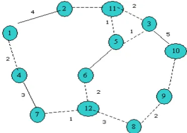
[image:4.595.309.495.55.187.2]The Light topology details and flow we used for our simulation are shown in the figure. The dotted lines between two nodes represent the fact that they are within each other’s “Hearing range”.
[image:4.595.309.531.211.352.2]Figure 4: Light Load Topology.
Figure 5: Overall throughput for Light load topology. Topology B: Moderately Heavy
The Moderately heavy topology details and flow we used for our simulation are shown in the figure. The Dotted lines between two nodes represent the fact that they are within each other’s “Hearing range”.
Figure 6: Moderate Heavy Load topology.
Figure 7: Overall throughput for Moderate Heavy load topology.
Topology C: Heavy Load
[image:4.595.47.253.346.677.2]The Heavy topology details and flow we used for our simulation are shown in the figure. The dotted lines between two nodes represent the fact that they are within other’s “Hearing range”.
Figure 8: Heavy Load Topology.
Figure 9: Overall throughput for Heavy load topology.
Overall throughput for Light Load
0 100 200 300 400 500 600
5 10 15 20 25 30 35 40
Time in seconds
K
b
y
t
es/
sec
MMMP_S_SD
M3P2
Overall Throughput for moderate load
0 100 200 300 400 500 600
5 10 15 20 25 30 35 40
Time in seconds
K
b
yt
es
/se
c
MMMP_S_SD M3P2
Overall Throughput for heavy load
0 200 400 600 800 1000 1200
5 10 15 20 25 30 35 40
Time in seconds
K
b
yt
es
/s
ec
[image:4.595.310.509.476.712.2] [image:4.595.45.249.503.665.2]V. RESULTS AND THEIR ANALYSIS
The schemes MMMP_S_SD, MPPC – are tested for different performance measures as described below.
A. Overall Throughput
[image:5.595.303.525.101.252.2]Overall throughput is calculated as the total number of bytes transmitted in the network in one second. This includes the transmission of RTS, CTS, DATA, and ACK packets. The overall throughput of each scheme for light, moderately heavy and heavy topologies as obtained from the simulations is listed in Table 1. The overall throughput for different schemes (Figure10) shows that the throughput for IEEE 802_11 compares poorly with the other schemes for all test loads. IEEE 802_11 therefore is not compared for later features.
Table 1: Overall throughput (Kbytes/sec) obtained from simulations for different schemes for varying loads.
Light (6)
Mod. Heavy
(8)
Heavy (12) MMMP_S_S
D
346.71 380.334 487.576
MPPC 501.128 549.858 983.191
802_11 4.680 96.075 136.290
Figure 10: Overall throughput (Kbytes/sec) obtained from simulations for different schemes for varying loads
B. Overhead due to Control packets
Overhead due to control packets are the total number of Kbytes transmitted as control packets in one second in the network. The control packets are RTS, CTS, and ACK packets. The simulation results showing the overhead due to control packets for the different schemes and network loading conditions are shown in Table 2.
Table 2: Traffic Characteristics Before (B) and After (A) Algorithm Implementation
Light (6)
Moderately Heavy (8)
Heavy (12) MMMP_S_S
D 27.59 27.3 43.04
MPPC 28.07 27.98 50.02
Figure 11: Overhead due to Control Packets.
C. Average Delay
[image:5.595.39.264.269.514.2]Delay is the total time that a packet takes to travel from source to final destination. Average delay is the average of the delays for all packets in the network. The average and the minimum and maximum of average delays are also shown in Table 3 and Figure 10.
Table 3: Average, minimum and maximum delays for different schemes and loads (ms)
MPPC
Avg.
Min (Avg.)
Max (Avg.)
Light 10.845 8.25 13.44
Mod. Heavy 10.76 8.75 12.77
Heavy 15.325 3.83 26.82
MMMP_S_
SD Avg.
Min (Avg.)
Max (Avg.)
Light 13.045 10.75 15.34
Mod. Heavy 12.8 10.32 15.30
Heavy 16.85 5.09 28.61
Figure 12: Average end-to-end delay
VI. CONCLUSION
The MAC protocol literature was surveyed to understand the state of the field and the existing level of research. There are several QoS issues in the MAC layer of Ad hoc networks, and the existing MAC protocols have largely concentrated on
Overall Throughput Varying load
0 200 400 600 800 1000 1200
LIGHT(6) MODERATE(8) HEAVY(12)
Load (active nodes)
Kbytes.sec
MMMP_S_SD M3P2 802_11
Ovearhead
0 10 20 30 40 50 60
LIGHT(6) MODERATE(8) HEAVY(12)
Load(Active nodes)
K
b
yt
e
s/
s
ec
MMMP_S_SD
M3P2
Average end-to-end delay for various schemas
0 2 4 6 8 10 12 14 16 18
LIGHT(6) MODERATE(8) HEAVY(12)
Load(Active nodes)
A
v
er
a
g
e D
el
ay
(m
s)
[image:5.595.304.522.393.693.2]improving and optimizing these issues in isolation of each other. Here, we introduce a new QoS-aware Mac protocol for Ad hoc networks that simultaneously addresses several QoS issues. The new protocol, called QoS-aware Mac Protocol with Power Control (MPPC) is a scheme that reduces exposed terminal problems, provides different QoS requirements, increases the life of battery driven devices with power control, and reduces co-channel interference. A range of simulations was used to test the performance of the protocol and the efficacy of its features under varying network load conditions. As expected, proposed scheme performed much better than IEEE 802.11 for all load conditions. The simulation results point out that the performance of our scheme is largely invariant for light and moderately heavy loads. In heavily loaded networks, however, for performance measures such as throughput, Average delay, the overall MPPC scheme with power control is seen to be the best. This schema can be implemented with incorporating node mobility. Though our proposed scheme is not implemented using Multi-hop though it works efficiently, this is something to be implemented for future.
REFERENCES
[1] S. Chakrabarti and A Mishra, “QoS Issues in Ad Hoc Wireless Networks”, IEEE Communications Magazine, Vol. 39, No. 2, February 2001.
[2] J. J. Garcia-Luna-Aceves and J. Raju, “Distributed Assignment of Codes for Multihop Packet-Radio Networks”, IEEE MILCOM, November 1997 Barbara Hughes and Vinny Cahill, “Towards Real-time Event-based Communication in Mobile Ad Hoc Wireless Networks.” 2nd International Workshop on real-time LANs in the Internet Age, 2003.
[3] Y. B. Ko and N. H. Vaidya, “Location Aided Routing (LAR) in Mobile Ad Hoc Networks”, ACM MOBICOM, 1998.
[4] V. Bhargavan, A. Demers, S. Shenker and L. Zhang, “MACAW: A Media Access Protocol for Wireless LANs,” Proc. ACM SIGCOMM, 1994, pp. 212-225.
[5] S.Kumar, V.S.Raghavan, J.Deng, “Medium Access Control Protocols For Ad-Hoc Wireless Networks: A Survey”.
[6] S. L. Wu, Y. C. Tseng, C. Y. Lin and J. P. Sheu, "A Multi-Channel MAC Protocol with Power Control for Multi-Hop Mobile Ad-Hoc Networks", The Computer Journal (SCI), Vol. 45, No. 1, 2002, pp. 101-110
[7] S. Singh and C. S. Raghavendra, "PAMAS - Power Aware Multi-Access protocol with Signaling for Ad Hoc Networks", ACM Computer Communication Review, Vol. 28, No. 3, July 1998, pp. 5-26. [8] E. -S. Jung and N. H. Vaidya, “An energy efficient MAC protocol for
wireless LANs,” IEEE INFOCOM, June 2002.
[9] IEEE 802.11 Working Group, “Wireless LAN Medium Access Control (MAC) and Physical Layer (PHY) Specification”, 1997.
[10] H. Woesner, J. P. Ebert, M. Schlager and A. Wolisz, “Power Saving Mechanisms in Emerging Standards for Wireless LANs: the MAC Level Perspective,” IEEE Personal Commun. Vol. 5(3), 1998, pp. 40-48.
[11] J. P. Ebert, B. Stremmel, E. Wiederhold and A. Wolisz, “An Energy-Efficient Power Control Approach for WLANs,” J. Commun. and Networks (JCN), Vol. 2(3), pp. 197-206, 2000.
[12] L. M. Feeney and M. Nilsson, “Investigating the Energy Consumption of a Wireless Network Interface in an Ad Hoc Networking Environment,” IEEE INFOCOM, April 2001.
[13] C. R. Lin and M. Gerla, "MACA/PR: An Asynchronous Multimedia Multihop Wireless Network", Proceedings of IEEE INFOCOM '97, March 1997
![Figure 2: Illustration of a case where RTS/CTS approach does not entirely resolve the hidden terminal problem [5]](https://thumb-us.123doks.com/thumbv2/123dok_us/1321569.662657/2.595.51.244.388.520/figure-illustration-approach-entirely-resolve-hidden-terminal-problem.webp)