Image Compression Preprocessing for ANN
Ensemble Motion Detection System
Kevin Emanuel Moorgas, Member, IAENG
Abstract – This paper presents image compression as an alternative method to preprocessing for an artificial neural network (ANN) motion detection system. Discrete wavelet transforms (DWT) and the discrete cosine transform (DCT) are used as preprocessing compression methods to improve the processing time of the ANN system used for object motion, detection, extraction and filtering. Configuring the ANN system as an ensemble was advantageous for improved noise cancellation of the end processing images. A comparison of the different image compression preprocessing methods is also presented during testing of the performance of the ANN ensemble motion detection system.
Index terms - artificial neural networks, wavelet transform,
compression, ensembles, filtering, discrete cosine transform
I. INTRODUCTION
Image compression preprocessing methods are used in most image communication systems with limited bandwidth to reducing image data size [4], [5]. The DWT and the DCT are widely used for image compression applications over a variety of scientific and engineering disciplines [14], [17], [22]. When the DWT was introduced it was the favored transform for image compression over other transformation methods for both lossy and lossless compression of data [13]. Wavelets have an added advantage in that they can also be used for de-noising images, image decomposition and image reconstruction [4], [20]. Wavelets provide added flexibility in signal and image compression in that there are many wavelet functions designed for specific handling of data and compression applications [5], [17].
The DCT is derived from the Fourier Transform (FT) and is also used for image and data compression [4], [13]. The major advantages of wavelets over the FT and the DCT is that it provides vital time scaling analysis, uses filter banks for de-noising, coding gain for sub-band image coding which is attributable to memory reduction, spectral flattening of sub-band signals that enables more accurate statistical modeling and efficient entropy coding of a signal[4],[5], [6], [8].
WCE Proceedings 2010
Paper first received 23 March 2010 and in revised form 15 April 2010. The work was supported by the Durban University of Technology.
Author: Department of Electronic Engineering, Durban University of Technology, South Africa.
Email ([email protected])
The ANN ensemble system that performs the object motion detection, extraction and filtering functions was proposed by Moorgas and Govender [16]. It outperforms the conventional DSP motion detection systems in terms of superior image quality save computational time. In this study the standard DCT and popular wavelet algorithms are used as image compressors for preprocessing to improve the computational speed of the ANN ensemble motion detection system (AEMDS) [16], [19].
ANN systems are used because they can generalize, are robust and inherently immune to noise [9], [11]. Furthermore changes in input data, such as illumination and varying noise levels, are handled more robustly by ANN systems [4], [9], [10]. In this study the DCT, Haar, Daubechies, and biorthogonal wavelets are applied as image compression preprocessors to the AEMDS to improve the system processing time.
This paper is arranged as follows: section 2 briefly introduces the architecture and operation of the AEMDS system; section 3 discusses the image compression preprocessing methods used; section 4 presents the performance of the AEMDS system when image compression is applied as preprocessing; section 5 concludes the study.
II. ANN ENSEMBLE MOTION DETECTION SYSTEM
(AEMDS)
The AEMDS shown in Fig. 1 uses multilayer feedforward (MLFF) backpropagation networks and a log-sigmoid nonlinear activation function to detect motion and remove any stationary background. The MLFF architecture was designed with two hidden layers and an output layer, having 100, 200 and 255 neurons respectively [12]. The output layer maped corresponding pixel elements from an input image matrix to the output image matrix. The AEMDS had two layers of NN ensembles to perform the motion detection function, extraction and filtering. This configuration produced high quality end processing images [13], [16].
Fig.1: ANN Ensemble motion detection system (AEMDS) (Source: Moorgas and Govender, 2008)
A. Testing
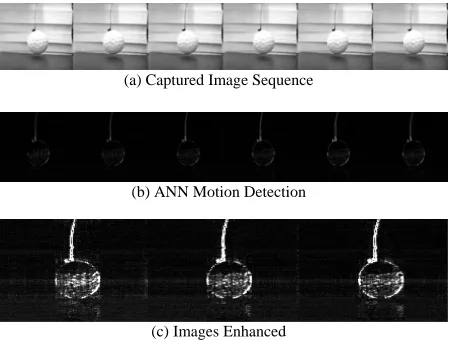
Initial testing was conducted with no image compression or noise as shown in Fig. 2. Gray scaled image sequences were captured, each image frame within the sequence was split into single frames and presented to the input of the ANN system. The AEMDS system detected any motion and displayed the new position of the object.
(a) Captured Image Sequence
(b) ANN Motion Detection
(c) Images Enhanced
Fig 2: Motion Detection of the AEMDS system without preprocessing and noise
III. IMAGE COMPRESSION
The main focus of this study was to consider the application of image compression preprocessing in object motion detection, extraction and filtering, with a view to improving the processing speed of the AEMDS system and still retain high quality images. (1) represents a captured frame sequence presented to the input of the AEMDS after image compression and the introduction of noise, Fig. 3(c), Fig. 4(c), Fig. 5 (c) and Fig. 6 (c).
Sβ = [H1, H2, … Hnth] (1)
Where Sβis an image frame sequence, β the sequence
number with H1, H2, … Hnth representing the image
frame matrices of the captured image sequence.
A. DCT Compression
In transform coding the compression technique applied divides an image into small non-overlapping blocks of
equal size M x N dimensions. The blocks are then
processed independently using the 2D-DCT transform in the frequency domain [6], [18]. With regard to (2), the 2D-DCT of an image is a sum of sinusoids of varying magnitudes and frequencies. After computation of the 2D-DCT, the significant information of the image is represented by coefficients. (3) is the 2D-IDCT which then converts this information back to the time domain [6], [8], [22]. For this study the 2D-DCT and the 2D-IDCT was
modified and applied to the M x N image matrix of
each image frame within each captured sequence with
] , [x y
fβ representing each image frame, β denoting
the frame number within each image sequence, x and y
representing the rows and columns of the image frame
matrices and p and q denotes the frequency variables.
(2)
(3)
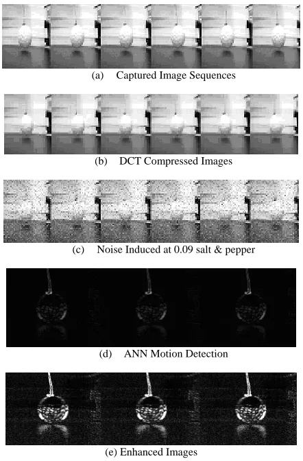
In Fig.3: an image sequence is captured in Fig 3(a), DCT image compression is applied to image frames in Fig. 3(b), noise is induced in each frame in Fig. 3(c), ANN motion detection, extraction and filtering is shown in Fig. 3(d) and the image frames are enhanced in Fig. 3(e).
1 0
, 1 0
2 ) 1 2 ( cos 2
) 1 2 ( cos ] , [ )
, (
1
0 1
0
− ≤ ≤ − ≤ ≤
+ +
=
∑∑
−= −
=
N q M
p
N q y M
p x y
x f q
p
F M
x N
y q p
π π
α
α β
1 0
, 1 0
2 ) 1 2 ( cos 2
) 1 2 ( cos ) , ( ]
, [
1
0 1
0
− ≤ ≤ − ≤ ≤
+ +
=
∑∑
−= −
=
N y M
x
N q y M
p x q
p F y
x
f M
p N
q q p
π π
α α
[image:2.612.64.291.508.681.2](a) Captured Image Sequences
(b) DCT Compressed Images
(c) Noise Induced at 0.09 salt & pepper
(d) ANN Motion Detection
[image:3.612.63.284.69.405.2](e) Enhanced Images
Fig 3: Motion Detection of the AEMDS using DCT Image Compression as Pre-processing
B: DWT Compression
The disadvantage of the DCT like the FT is that it only caters for frequency resolution and not time resolution [18], [6]. This means that only the frequencies within a signal can be determined but not the time at which these frequencies were introduced to the signal. The DWT is used to overcome the shortcomings of the DCT and the DFT [8], [18]. The WT and DWT are used extensively in image processing applications (for segmentation, morphological operations and image compression) and exhibits superior performance over most other image compression methods [8].
For this study the Haar, Daubechies Wavelets (db4) and biorthogonal wavelets (bior 1.3) wavelets were used as image compression preprocessing algorithms to test the AEMDS system with the objective of reducing the detection, time of the ANN motion detection system.
The scaling function of the two dimensional wavelet
isϕ(x,y), and the three two dimensional directional
wavelets are,ψH(x,y),
) ,
(x y
V
ψ and ψD(x,y) which are
defined by (4), (5) and (6): H(horizontal), V(vertical)
and D(diagonal) are the directional wavelet indicators.
They measure intensity variations along columns, rows and diagonals of an image matrix [3], [6], [8].
)
(
)
(
)
,
(
x
y
x
y
H
ψ
ϕ
ψ
=
(4)
)
(
)
(
)
,
(
x
y
x
y
V
ϕ
ϕ
ψ
=
(5))
(
)
(
)
,
(
x
y
x
y
D
ψ
ψ
ψ
=
(6)The scaled and translated basis functions are defined as follows:
)
2
,
2
(
2
)
,
(
/2,
,
x
y
x
m
y
n
j j
j n
m
j
=
ϕ
−
−
ϕ
(7))
2
,
2
(
2
)
,
(
/2,
,mn
x
y
j i jx
m
jy
n
j
i
=
ψ
−
−
ψ
(8)With regards to (7) and (8) i assumes the value H, V,
and D to identify the directional wavelets, j denotes
the resolution level of the image framefβ[x,y]
having x–rows and y-columns. The 2D-DWT is
defined by (9) and (10) for the image frames within
the image frame sequencesfβ[x,y] of size M x N.
) , ,
(j m n
Wϕ are coefficients defined as approximations
of fβ[x,y] with j0 the starting scale. The
) , , (j mn
Wi
ψ coefficients add horizontal, vertical and
diagonal details for scales j. N=M=2j so that j = 0, 1,
2, …, j – 1 and m = n = 0, 1, 2, …, 2j – 1.
∑∑
−= −
=
= 1
0 1
0
0 [ , ] , , ( , )
1 ) , , (
M
x N
y
j m n x y
y x f MN
n m j
Wϕ β ϕ (9)
∑∑
−= −
=
= 1
0 1
0
) , ( , , ] , [ 1
) , , (
M
x N
y
i j
i f x y mn x y
MN n
m j
Wψ β ψ (10)
A captured image frame fβ[x,y]contains a vector
space
V
j which has2
jpixels inV
j with j = 0, 1, 2….n-1.
B.1 Haar Wavelet Compression
The Haar wavelet is used for most image processing applications because of its simple algorithm, high compression processing time and compactness [5], [21]. (8) is the conventional 2D Haar wavelet scaled and translated box functions.
1 2 ... 2 , 1 , 0 )
2 ( : )
( = j − = j−
j
i x φ x i wherei
φ (8)
⎭ ⎬ ⎫ ⎩
⎨
⎧ ≤ <
=
otherwise x for
x 0 1
0 1 ) ( φ
1 2 ... 2 , 1 , 0 )
2 ( : )
( = j − = j−
j
i x ψ x i wherei
ψ (9)
⎪ ⎭ ⎪ ⎬ ⎫
⎪ ⎩ ⎪ ⎨ ⎧
< ≤ −
< ≤ =
otherwise x for
x for x
0
1 2
/ 1 1
2 / 1 0
1 : ) (
ψ
The 2D DWT of fβ[x,y] was obtained from the 1D
DWT by multiplying two 1D scaling functions that
scan horizontal, vertical and diagonal details of the
image frame [23]. Results of the Haar compression preprocessing is shown in Fig.4. Fig. 4(a) is the captured image sequence, Fig.4(b) is Haar compressed image frames of the image sequence, Fig.4(c) is the introduction of noise, Fig.4(d) is the ANN motion detection, extraction and filtering and Fig.4(e) is the enhanced images image frames.
(a) Captured Image Sequences
(b) Haar Wavelet Compressed Images
(c) Noise Induced at 0.09 Salt & Pepper
(d) ANN Motion Detection
(e) Enhanced Images
Fig.4: Motion Detection of the AEMDS using Haar Wavelet Compression
B.2 Daubechies Wavelet Compression
Daubechies’ wavelets are used in image analysis and synthesis because they are orthonormal, have continuous derivatives (images are smooth except occasional edges) and compact algorithms [24], [25]. The Daubechies’ wavelets have quadratic mirror filters of the Haar wavelet [7]. Like the Haar wavelet the Daubechies’ wavelet was translated for any image
framefβ[x,y]within the captured sequence. Results of
the motion detection are shown in Fig.5 using the Daubechies’ compression algorithm. Fig.5(a) is the captured image sequence, Fig. 5(b) using Daubechies (db4) for image frame compression, Fig.5(c) is induced noise, Fig. 5(d) ANN motion detection, object extraction and filtering and Fig.5(e) is image enhancement of each frame.
B.3 Biorthogonal Wavelet Compression
Biorthogonal Wavelets exhibit properties of linear phase which is needed for signal and image
reconstruction and analysis [17]. They are excellent
for image coding and de-noising [1]. Many elegant quantization and entropy coding techniques have been developed that exploit the multi-resolution nature of this wavelet family to enhance the low bit rate coding of images [26]. The properties of the biorthogonal wavelets have duality in any subspace because of its symmetry and separate decomposition and reconstruction functions in each member of its family of wavelets [20]. The scaling functions are obtained by
multiplication for a vector space
V
j which can betranslated to an image matrix framefβ[x,y]. During
testing the biorthogonal (bior1.3) wavelet algorithm was applied.
(a) Captured Image Sequences
(e) Daubechies (db4) Wavelet Compressed Images
(c) Noise Induced at 0.09 Salt & Pepper
(d) ANN Motion Detection
(e) Enhanced Images
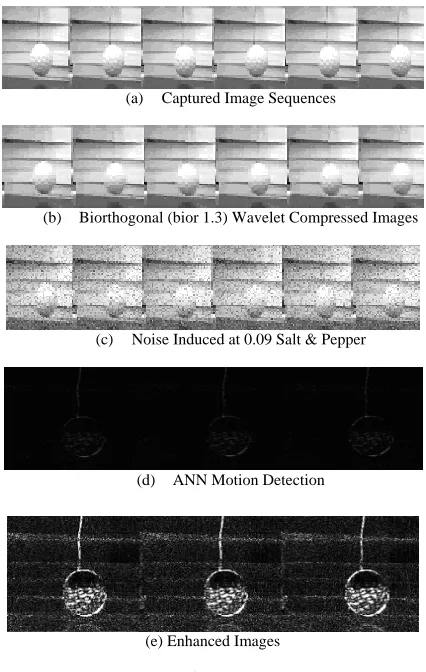
The results of the AEMDS system using the biorthogonal image compression as preprocessing are shown in Fig.6. Fig.6(a) is the captured image sequence, Fig.6(b) is the biorthogonal image compression (bior1.3), Fig. 6(c) is induced noise, Fig. 6(d) is the ANN motion detection, object extraction and filtering and Fig 6 (e) is image enhancement.
(a) Captured Image Sequences
(b) Biorthogonal (bior 1.3) Wavelet Compressed Images
(c) Noise Induced at 0.09 Salt & Pepper
(d) ANN Motion Detection
[image:5.612.67.280.161.497.2](e) Enhanced Images
Fig. 6: Motion Detection of the AEMDS using Biorthogonal (bior 1.3) Wavelet Compression
IV. PERFORMANCEOFTHE AEMDS WITH IMAGE
COMPRESSION
A. Noise
The Peak Signal-to-Noise Ratio (PSNR) (10) is used to measure image quality of the image sequences produced by the AEMDS system.
MSE g g PSNR
2 min max 10
] [
log
10 −
= (10)
With regards to (10), gmax and gmin indicate the
maximum and minimum pixel values for an image
frame; MSE is the mean squared error for two
dimensional M x N gray scaled images. Fig 7 shows
PSNR response of the different preprocessing image compression methods applied to the AEMDS system.
With regard to Fig. 7:
Sequence 1image sequence is captured: Under identical conditions for each motion detection test (Fig. 3(a), Fig. 4(a), Fig. 5(a) and Fig. 6(a)).
Sequence 2, image frames are compressed: For each image frame within the captured sequences different image compression methods are applied (Fig. 3(b), Fig. 4(b), Fig. 5(b) and Fig. 6(b)).
Sequence 3, noise is induced: The same level of noise is induced to each frame of each image sequence (Fig. 3(c), Fig. 4(c), Fig. 5(c) and Fig. 6(c)).
Sequence 4, motion is detected: The AEMDS detects motion and improves the PSNR of each frame within the sequence (Fig. 3(d), Fig. 4(d), Fig. 5(d), and Fig. 6(d)).
Sequence 5, image enhancement: Each frame of the image sequence is enhanced to show the new position of the non – stationary object (Fig. 3(e), Fig. 4(e), Fig. 5(e), and Fig. 6(e)).
Fig 7: PSNR of Motion Detection with Image Compression Preprocessing
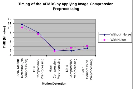
B. Average Processing Time
[image:5.612.319.549.339.504.2]Timing of the AEM DS by Applying Image Compression Preprocessing
4 5 6 7 8 9 10 11 12
A
NN M
ot
ion
De
te
c
ti
o
n (
No
c
o
m
pr
es
s
ion)
DCT
C
o
m
p
re
ssi
o
n
Pr
e
p
ro
c
e
ss
in
g
Ha
ar
C
o
m
p
re
ssi
o
n
Pr
e
p
ro
c
e
ss
in
g
Db
4
C
o
m
p
re
ssi
o
n
Pr
e
p
ro
c
e
ss
in
g
B
ior
1.
3
Com
p
re
s
s
io
n
P
re
p
ro
ce
ssi
n
g
Motion Detection
TIM
E
(
M
inu
te
s
)
Without Noise
[image:6.612.67.287.76.222.2]With Nois e
Fig. 8: Average Processing Time of the AEMDS V. CONCLUSION
This paper showed that the ANN ensemble motion detection system (AEMDS) used for object detection, extraction and filtering had improved processing time and still retained high image quality with the applied image compression preprocessing methods. The method of object motion detection, extraction and filtering presented proved superior to some conventional DSP motion detection systems.
ACKNOWLEDGMENT
This work is supported by the Durban University of Technology.
REFERENCES
[1] Alam M., Badawy W., Dimitrov V. and Jullien G., “An Efficient Architecture for Lifted 2D Biorthogonal DWT”, Journal of VLSI Signal Processing 40, 335-342, 2005, Springer Science + Business Media, Inc.
[2] Aboufadel E. and Schlicker S., “Discovering Wavelets”, Wiley-Interscience, published 1999.
[3] Antonini M., Barlaud M., Mathieu P., and Daubechies I., ‘Image Coding Using Wavelet Transform’, IEEE Trans. Image Processing Vol. 1. NO 2, April 1992, pp 205 - 220.
[4] Bitten J.R. and Dr. Osorio F.S., “Adaptive Filters for Image Processing based on Artificial Neural Networks”, Proceedings of the Brazilian Symposium on Computer Graphics and Image Processing, IEEE (SIBGRAPI ’00). ISBN 0-7695-0878-2/00, 2000.
[5] Buckheit J.B. and Donoho D.L., “Wavelab and Reproducible Research Technical Report”, Department of Statistics, Stanford University, Stanford Califonia, USA, 1995.
[6] Dai Q, Chen X, and Lin C, “Fast Algorithm for Multidimensional DCT to DCT Computation Between a Block and Its Associated Subblocks”, IEEE, 1053-587X, pp 3219 – 3225, 2005.
[7] Elfouly F.H., Mahmoud M.I., Dessouky I.M., and Deyab S., “Comparison Between Haar and Daubechies Wavelet Transformations on FPGA Technology”, International Journal of Computer Information, Systems Science, and Engineering 2;1 WASET 2008.
[8] Gonzalez R.C. and Woods R.E., “Digital Image Processing”, Pearson Prentice Hall, Third Edition, Published 2008. [9] Govender P., Singh R., Paramanund C., Naicker A., Bright G.,
“Industrial Quality Assurance Using Artificial Intelligence”, Published, 2006.
[10] Hagan M.T., Demuth H.B., and Beale M.H., “Neural Network Design”, Boston, MA: PWS Publishing,1996.
[11] Hansen L.K. and Salamon P., “Neural Network Ensembles”,
IEEE Transactions on Pattern Analysis and Machine Intelligence, Vol. 12, Number 10, pp 993- 1001, 1990.
[12] [12] Ham F.M. and Kostanic I., “Principles of Neurocomputing for Science and Engineering”, Mc Graw Hill, Published, 2001.
[13] Hilton M.L., Jawerth B.D. and Segupta A., “Compression Still and Moving images with wavelets”, Mutimedia Systems, Springer-Verlag(1994) 2:218-227.
[14] Khare A. and Tiwary U.S., “Daubechies Complex Wavelet Transform Based Technique for Denoising of Medical Images”, International Journal of Image and Graphics, Vol 7, No.4 (2007) 663-687, World Scientific Publishing Company. [15] Liu M., Jiang X., Kot A. C., “Nonlinear Fingerprint
Orientation Smoothing by Median Filter”,IEEE Information, Communications and Signal Processing, Fifth International Conferernce, Vol. Issue 2005 pp 1439-1443.
[16] Moorgas K.E. and Govender P., “DSP Systems vs ANN Ensembles for Motion Detection and Filtering”, Conference Proceedings, World Congress of Engineering and Computer Science, WCECS 2008, pp 1129-1134.
[17] Menegaz G., “Trends in Medical Image Compression”, Current Medical Imaging Reviews, 2, 165-185, Bentham Science Publishers Ltd, 2006.
[18] Najarian K., and Splinter R., “Biomedical Signal and Image Processing”, Taylor & Francis CRC Press, Published, 2006. [19] Polikar R., “Ensemble Based Systems”, IEEE magazine
circuits and systems 2006, 1531-636X/06/. pp 21 – 45. [20] Pragada S. and Sivaswamy J., “Image Denoising Using
Matched Biorthogonal Wavelets”,Sixth Indian Conference on Computer Vision, Graphics & Processing, 978-07695-3476-3/08, 2008 IEEE, DOI 10.1109/ICVGIP.2008.95.
[21] Raviraj P. and Sanavullah M.Y., “The Modified 2D - Haar Wavelet Transformation in Image Compression”, Middle-East Journal of Scientific Research 2 (2) 73-78, 2007, ISSN 1990-9233, IDOSI Publication, 2007.
[22] Riazifar N. and Yazdi M., “Effectiveness of Contourlet vs Wavelet Transform on Medical Image Compression: A Comparative Study”, Proceedings of World Academy of Science, Engineering and Technology (PWASET) Vol. 37, January 2009 ISSN 2070-3740.
[23] Talukder K.H. and Harada K., “Haar Wavelet Based Approach for Image Compression and Quality Assessment of Compressed Images”, IAENG International Journal of Applied Mathematics, 36:1, IJAM 36 1 9, Online publication 1 February 2007.
[24] Wang J.Z., Wiederhold G., Firschein O and Wei S.Z., “Content Based Image Indexing and searching using Daubechies Wavelets”, International Journal on Digital Libraries, Springer-Verlag 1997, Vol. 1 pp311- 328.
[25] Wang J.Z., Wiederhold G., Firschein O. and Wei S. X., “Content – based Image Indexing and Searching Using Daubechies’ Wavelets.”, Digital Libraries, Springer – Verlag (1997) 1:311-328.