Abstract—The subtalar joint is in neutral when it is neither pronated nor supinated, which the posterior midline of the calcaneus is vertically aligned with the calf and perpendicular to the forefoot. The incorrect foot position causing excessive and prolonged pronation during standing phase with biomechanical abnormalities would be believed to increase the risk of overuse injuries. It is important to understand as it forms the key reference point for much of the assessment and fabrication for foot orthoses. In this paper, the assessment of the subtalar joint neutral position was applied by building eversionable foot platforms and capturing the rearfoot images for image processing analysis. Finally, the subtalar joint neutral position was determined for the various the tilt angles of the foot platforms.
Index Terms—Foot, subtalar joint, neutral position, image processing
I. INTRODUCTION
HE foot and ankle have been supported the weight of the
human body and overcome the reaction force from the ground. For the bones of the foot as shown in Fig. 1, the subtalar joint (STJ) is located between the talus and calcaneus, and the ankle joint is located between the tibia and talus. When the STJ is in a neutral position, the joint is neither pronated nor supinated, and the longitudinal midlines of the leg and calcaneus are in alignment [1]. The maximum contact between calcaneal and tibial facets for transmitting ground reaction forces through STJ. The STJ is very important as it influences the rotational forces of the tibia and the superstructures [2]. If the STJ is pronated, the anatomy of the tibia and the talus will cause the tibia to rotate internally, moving the knee medial to the foot, and hip and knee joints will flex [3,4]. Therefore, STJ neutral position is significant and widely used position for clinical practice. Several methods for locating and measuring STJ neutrality have been described by Root et al. [5], Bailey et al. [6], Wernick and Langer [7], James et al. [8], Sell et al. [9], and Najjarine [10].
Manuscript received February 28, 2017; revised April 24, 2017. This work was supported in part by the supported by Taiwan’s Ministry of Science and Technology under Grant MOST 105-2221-E-034-010.
Chien-Hung Lin is with the Department of Mechanical Engineering, Chinese Culture University, Taipei 11114, Taiwan R.O.C. (corresponding author to provide phone: 886-2-2861-0511#33311; e-mail: [email protected]. edu.tw).
Chan-Chia Yeh, was with the Department of Mechanical Engineering, Chinese Culture University, Taipei, Taiwan R.O.C. (e-mail: bardy891307@gmail. com).
Zeng-Hui Qiu was with the Department of Mechanical Engineering, Chinese Culture University, Taipei, Taiwan R.O.C. (e-mail: [email protected]).
(a) (b) (c)
Fig. 1. Anatomy of left rearfoot: (a) pronation, (b) neutral, and (c) supination.
In general, markers are painted on the patient’s lower leg and calcaneus, and then a goniometer is used to measure the angle between the midlines of the calcaneus and leg. Pronation refers to an inward roll of the foot during normal motion and occurs as the outer edge of the heel strikes the ground and the foot rolls inward and flattens out. Supination is the opposite process and refers to the outward roll of the foot during normal motion. However, the clinician in assessing subtalar joint neutral position has poor repeatability, which is dependent on the clinician’s experience and subjective judgment. In this paper, the assessment of STJ neutral position was applied by building eversionable foot platforms and capturing the rearfoot images for image processing analysis. The left- and right-foot of the subject stood on the eversionable left- and right- foot platforms, respectively, then the foot platforms were rotated the angle. The rearfoot images were enhanced with edge detection by image processing, providing an objective and automatic method of calculating the midlines of the tibia and calcaneus. The rotating angle of the foot platforms denoted the STJ neutral position when the slopes of the midlines of the calcaneus and tibia were closer.
II. METHODOLOGY
A. Subjects
The subject was a man of healthy individual with no previous foot problems. He was 22 years old and his weight and height were 62 kg and 179 cm, respectively. The subject was assessed STJ neutral position by the image processing.
B. Eversionable Foot Platforms
To assess STJ neutral position, the eversionable foot platforms was necessary for measurement as shown in Fig. 2. The frame of platforms were made of aluminum extrusion, and the top of left and right platforms was able to be tilted independently to invert the left and right foots, respectively. The foot platform was tilted by the rise and fall of the linear
Assessment of Subtalar Joint Neutral Position:
Study of Image Processing for Rear Foot Image
C. H. Lin, C. C. Yeh, and Z. H. Qiu
[image:1.595.305.548.170.300.2]Fig. 2. Eversionable foot platforms design.
actuator, where the linear actuator consisted of DC motor, gears, and screw that provides the maximum thrust of 1800 N, the maximum pulling force of 1200 N, the maximum stroke of 100 mm, the input voltage of 24 V, and the maximum current of 3 A. The linear actuator was driven by the dual H-bridge DC motor drive chip of L298N, which is controlled by an Arduino Uno to achieve the actuator rising or falling. Arduino Uno is a microcontroller board based on the ATmega328P, which has 14 digital input/output pins (of which 6 can be used as PWM outputs), 6 analog inputs, and a USB connection. The L298N drove two DC motors at the same time, which has a bridge circuit composed of four transistors as the switch. The connection between Arduino Uno, linear actuator, and L298N was shown in Fig. 3. To feedback the tilt angle of the foot platform by the linear actuator rising or falling, an accelerometer was placed under the foot platform. The accelerometer was a Freescale MMA7455 with three-axis digital output capacitive micromachined sensor for high-performance and low power.
C. Image Processing
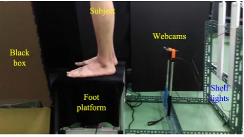
This paper investigates the application of digital image processing using rearfoot images for assessing the STJ neutral position. The foot image capturing system was consisted of black box, foot platform, webcams, and shelf lights as shown in Fig. 4. To avoid the light reflection, the black flannel was covered on the foot platform. The black flannel was also stuck inner of the black box. To determine the midlines of the calcaneus and the tibia, a foot image processing program was developed in MATLAB for the rearfoot images operating image acquisition, grayscale, edge detection, enhancement, and binary image to calculate and mark the midlines of the calcaneus and tibia. For the binary image, the rearfoot image was separated two regions: the upper region represented the profile of the lower leg for determining the midline of the tibia, and the lower region represented the profile of the Achilles tendon for determining the midline of the calcaneus. For instance, the positions of the lower leg profiles were detected pixel by pixel from both sides of the binary image inward in the upper region. The positions of the lower leg were found where the pixels had a typical white intensity value of 1. For dividing the region into four equal segments, ten points were marked, namely five positions on each side of the lower leg, then five midpoint coordinates were calculated and marked in the image. For the five midpoints of the tibia, the leg angle between the tibial midline and the horizontal line was be calculated by a numerical linear regression. The analytic method for the lower region was similar to that for the upper region.
[image:2.595.48.291.52.174.2]Fig. 3. The connection between Arduino UNO, linear actuator, and L298N.
Fig. 4. The foot image capturing system.
inside of the lower leg profiles. Therefore, the images was inspected pixel by pixel from both sides inward until detecting intensity of 1. The first captured position indicated part of the lower leg profile, and the second captured position identified part of the tendon profile. Similarly, the foot angle between the calcaneal midline and the horizontal line was be calculated by a numerical linear regression for the five midpoints of the calcaneus. The STJ neutral position occurred at the tilt angle of the foot platform when the foot and leg angles are the closest.
III. RESULTS
A. Eversionable Foot Platforms
The eversionable foot platforms were accomplished as shown in Fig. 5. The linear actuators were driven by SIMULINK for position control as shown in Fig. 6. For the accelerometer feedback signal, the accuracy of the platform in tilt angle is ±2 degrees, and the maximum tilt angle of the platform was about 18 degrees.
B. Image Processing
[image:2.595.307.548.242.377.2]Fig. 5. Eversionable foot platforms.
Fig. 6. Simulink model diagram of eversionable foot platforms.
lower leg and Achilles tendon were displayed with the white intensity value of 255, and the background was displayed with the black intensity value of 0 by the threshold method to convert the grayscale image into a binary image. Sixthly, the binary image was decreased noise by the low-pass filter operator. Seventhly, the points were marked on the edge profiles of the lower leg and Achilles tendon, which were detected pixel by pixel from both sides inward. Finally, the tibial and calcaneal midlines were calculated and displayed on the original capturing image. Consequently, the midline angle was calculated by the slope of midline.
C. STJ neutral position
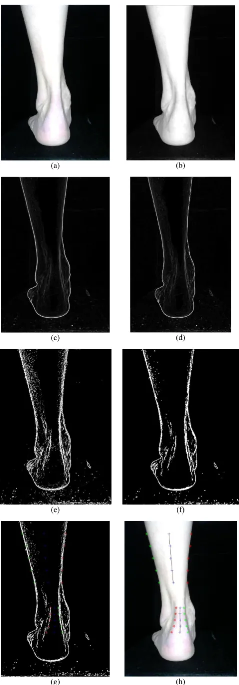
In experimental process, the left- and right-foot of the subject stood on the eversionable left- and right- foot platforms, respectively, then the foot platforms were rotated the angle and the rearfoot images were captured and saved by the webcams. The eversionable left- and right-foot platforms were tilted the angles of 0, 5, 10, and 15 degrees, respectively. The left- and right-rearfoot images were shown in Fig. 8 and Fig. 9, respectively. The midlines of the tibia and calcaneus were determined by marking the points at the edges of the lower leg and the Achilles tendon for the image processing. In the upper region of the rearfoot image, the leg angle was equal to the slope of the tibial midline which was calculated by a numerical linear regression for the five midpoints of the
(a) (b)
(c) (d)
(e) (f)
(g) (h)
[image:3.595.51.287.258.427.2](a) (b)
[image:4.595.49.287.50.383.2](c) (d)
Fig. 8. Left rearfoot images at the tilted angles: (a) 0, (b) grayscale image, (c) edge detection, (c) contrast enhancement, and (d) binary image.
(a) (b)
(c) (d)
Fig. 9. Right foot: (a) capturing image, (b) grayscale image, (c) edge detection, (c) contrast enhancement, and (d) binary image.
tibia. Correspondingly, in the lower region of the rearfoot image, the foot angle was equal to the slope of the calcaneal midline which was calculated by a numerical linear regression for the five midpoints of the calcaneus. The relationships between the tilt angle of the foot platform and the midlines were shown in Fig. 10. The angles of the midlines of the right foot had a significant effect on the tilt angle of the foot platform. The closest of angle difference between the tibial and calcaneal midlines was about 0 degree when the tilt angle of the foot platform was 10 degrees. As a result, the STJ neutral position was 10 degrees for the right foot. However, the angles of the midlines of the left foot had not significant effect on the tilt angle of the foot platform. All angles difference between the tibial and calcaneal were about 5 degrees when the foot platform was tilted 0, 5, 10, and 15 degrees. The closest of angle difference between the tibial and calcaneal midlines was about 4.5 degree when the tilt angle of the foot platform was 5 degrees. Consequently, the STJ neutral position was 5 degrees for the left foot. The left- and right-midline angles were different tendency, because the positions of the left- and right-foot were not symmetry or the location of the webcam was not placed proper position. For the tilt foot platform, the greater tilt angle is, the foot more easily slide down because it is not easy to stand on the platform. In future, the outer side of the foot platform would require a supported plate that provides the outside of the foot to support.
(a)
(b)
[image:4.595.323.531.397.760.2] [image:4.595.51.289.422.756.2]IV. CONCLUSION
In humans, the foot and ankle are one of the most complex musculoskeletal structures of the human body to serve as the primary interface between the ground and the body. The incorrect foot position causing excessive and prolonged pronation during standing phase with biomechanical abnormalities would be believed to increase the risk of overuse injuries. Using image processing the rearfoot image has dealt with edge detection can calculate objectively midlines of the calcaneus and the tibia. The eversionable foot platforms have been designed and accomplished to assess STJ neutral position. For the various the tilt angles of the foot platform, the STJ neutral position is able to be determined. The tilt angle of the foot platform denotes the STJ neutral position when the slopes of the midlines of the calcaneus and tibia are closer.
ACKNOWLEDGMENT
The authors are grateful for the support of the Ministry of Science and Technology of Taiwan R.O.C., by grant number MOST 105-2221-E-034-010. The authors would also like to thank Dr. Ching-Chieh Yang of Youngfore Hospital for his assistance.
REFERENCES
[1] D. J. Pratt, “Functional foot orthoses,” The Foot, vol. 5, no. 3, 1995, pp. 101-110.Available: http://dx.doi.org/10.1016/0958-2592(95)90000-4 [2] J. Perry, Gait Analysis Normal and Pathological Function (Book style).
New Jersey: SLACK Incorporated, 1992.
[3] D. Tiberio, “Pathomechanics of structural foot deformities (Journal paper style),” Phys Ther., vol. 68, 1988, pp.1840-1849.
[4] B. D. Cusick, “Splints and casts managing foot deformity in children with neuromuscular disorders (Journal paper style),” Phys Ther., vol. 68, 1988, pp. 1903-1912.
[5] M. L. Root, W. P. Orien, J. M. Weed, and R. J. Hughes, Biomechanical Examination of the Foot (Book style). vol. 1, Los Angeles: Clinical Biomechanics Corp, 1971.
[6] D. S. Bailey, J. T. Perillo, and M. Foreman, “Subtalar joint neutral: A study using tomography (Journal paper style),” J. Am. Podiat. Med. Assoc., vol. 74, no. 2, 1984, pp. 59-64.
[7] J. Wernick and S. Langer, A Practical Manual for a Basic Approach to Biomechanics (Book style). vol. 1, New York: Acrylic Laboratory, 1972.
[8] S. L. James, B. T. Bates, and L.R. Osternig, “Injuries to Runners
(Journal paper style),” Am. J. Sports Med., vol. 6, no. 2, 1978, pp. 40-49.
[9] K. E. Sell, T. M. Verity, T. W. Worrell, B. J. Pease, and J.
Wigglesworth, “Two Measurement Techniques for Assessing Subtalar Joint Position: A Reliability Study,” J. Orthop. Sports Phys. Ther., vol. 19, no. 3, 1994, pp. 162-167. Available:
http://www.jospt.org/doi/pdf/10.2519/jospt.1994.19.3.162?code=jospt -site
[10] A. Najjarine, “Finding NCSP Using the NAS Anterior Lines Method. Superior Biomechanics,” Newsletter, vol. 17, 2012, pp. 1-2, [Online]. Available: