A construction-specific simulation-based framework for
earthworks.
CLEGG, David Richard.
Available from Sheffield Hallam University Research Archive (SHURA) at: http://shura.shu.ac.uk/19480/
This document is the author deposited version. You are advised to consult the publisher's version if you wish to cite from it.
Published version
CLEGG, David Richard. (1999). A construction-specific simulation-based framework for earthworks. Doctoral, Sheffield Hallam University (United Kingdom)..
Copyright and re-use policy
See http://shura.shu.ac.uk/information.html
REFERENCE
*-ProQuest Number: 10694361
All rights reserved INFORMATION TO ALL USERS
The quality of this reproduction is dependent upon the quality of the copy submitted. In the unlikely event that the author did not send a com plete manuscript and there are missing pages, these will be noted. Also, if material had to be removed,
a note will indicate the deletion.
uest
ProQuest 10694361
Published by ProQuest LLC(2017). Copyright of the Dissertation is held by the Author.
All rights reserved.
This work is protected against unauthorized copying under Title 17, United States C ode Microform Edition © ProQuest LLC.
ProQuest LLC.
789 East Eisenhower Parkway P.O. Box 1346
A construction-specific
simulation-based framework for earthworks
David Richard Clegg
A thesis submitted in partial fulfilment of the requirement
of
Sheffield Hallam University
for the degree of Doctor of Philosophy
Abstract
Construction companies are operating within an increasingly competitive environment. Work often has to be tendered for on a very low profit basis. If the tender is too high, work is lost. If too low the contract may be won, but the job completed at a loss, unless more effective working methods can be found. Plans are used throughout the
construction industry to allocate resources and schedule work. Yet, the planning tools used; Gantt chart, PERT and Queuing theory to name but a few, represent jobs as if they are static in duration, which in the complex, dynamic construction environment are clearly inappropriate.
The EPSRC fuelled interest in developing a simulation methodology by suggesting that the construction industry could be considered similar to the traditional manufacturing industry. The manufacturing industry faced similar production dilemmas, work was completed but using inefficient resource configurations, causing bottlenecks, increased work-in-progress leading to higher costs. To reduce number of problems the
manufacturing industry sought to utilise and develop a planning technique that had the capacity for modelling the dynamic nature of the industry. Discrete-event simulation enables the problems associated with manufacturing to be anticipated and minimised, as opposed to constantly fire-fighting. Since using simulation has accrued such impressive benefits within the manufacturing industry it is therefore not without credence to
believe that the construction industry could also obtain saving from embracing this management tool.
Simulation has been applied to model a number of scenarios within the construction industry. Similarities between the applications were sought and an area for further development was identified. A problem was modeled using the most frequently encountered simulation paradigms found in the manufacturing and construction industries, ‘Activity cycle’ and ‘Process based’. Of the two methodologies, ‘Process based’ was selected for the development of further models.
A conclusion drawn from the research is that simulation is not being utilized within the construction industry due to the perception that it requires an excessive use of resources. The research project identified that the model building process may be simplified through the development of generic simulation modules. These generic modules enable a simulation model to be developed quickly and easily by a non-simulation practitioner.
Preface
This thesis is submitted to the Schools of Engineering and Construction, at Sheffield Hallam University for the degree of Doctor of Philosophy.
I would like to express my gratitude to my supervisors Dr. D.T. Perera, Dr. P. Stephenson and Mr J. Ridal, for their guidance and constructive criticism throughout the course of this study.
I would like to thank the engineers at Balfour Beatty for their time, without which it would have been impossible to develop simulation models of the construction processes.
The results obtained during the course of this research are to the best of my knowledge original, except where reference is made to the work of others.
Table of Contents
Abstract... II Preface...Ill
1 INTRODUCTION... 1
1.1 Aims of the research...2
1.2 Objectives of the research... 3
1.3 Structure of the thesis...4
1.4 Scope and Limitations of the research...6
2 LITERATURE REVIEW ...7
2.1 Introduction...7
2.2 Planning techniques...7
2.2.1 Types o f planning tools...8
2.2.2 Graphical models:- the Gantt (Bar) chart...9
2.2.3 Linked bar charts...10
2.2.4 Network modelling tools...11
2.2.5 PERT...12
2.3 What is Simulation?... 14
2.3.1 Simulation and Modelling Philosophy...14
2.3.2 Why simulate?...16
2.4 Activity cycle, Event Vs Process based simulation... 18
2.4.1 Introduction...18
2.4.2 Selection o f modelling methodology...18
2.4.3 Activity cycle methodology...18
2.4.4 Event-based approach...20
2.4.5 Process based...22
2.5 Comparison of Methodologies...24
2.6 Overview of where simulation has been used in construction 25 2.6.1 Use o f Simulation within the Construction Industry...30
2.6.2 Proposed Applications o f simulation...36
2.6.4 Justification o f current work...42
2.6.5 Problem statement...45
3 PLANNING EARTHMOVING: COMPARISON BETWEEN MATHEMATICS, ACTIVITY-BASED AND PROCESS-BASED SIMULATION... 47
3.1 Introduction...47
3.2 Planning Earth-moving...48
3.2.1 Method o f excavation...49
3.2.2 Summary...53
3.2.3 MicroCyclone Simulation model...53
3.2.4 How the results were obtained...56
3.2.5 Comparison o f Results...56
3.2.6 Comparison o f results: observations versus simulation versus mathematics...59
3.2.7 Summary; Mathematical vs simulation vs actual output. 62 3.3 Software selection... 63
3.3.1 Conclusion to the Chapter...66
4 ANALYSIS OF SIGNIFICANT FACTORS...67
4.1 Introduction...67
4.2 Factorial Arrangement... 68
4.2.1 Problem...69
4.2.2 Experimental design...71
4.2.3 Results...72
4.2.4 Interaction effects...74
4.2.5 Calculation o f Error Term...75
4.2.6 Interpretation o f results...76
4.2.7 Conclusions to factor analysis experiments...81
4.3 Further investigation of significant factors...82
4.3.2 How were the breaks included in the model?...85
4.3.3 Conclusions to the experiments: modeling earthworks as a terminating or nonterminating system...87
4.4 Single Versus multiple chainages...89
4.4.1 Introduction...89
4.4.2 Problem definition...90
4.4.3 Results...91
4.4.4 Conclusion to single versus multiple chainages...96
4.5 Conclusion to the Chapter...96
5 DEVELOPMENT OF GENERIC MODULES... 98
5.1 Introduction... 98
5.2 Module Overview...99
5.3 Model formulation...100
5.4 Communicative model...101
5.5 Main topic Single chainage...102
5.5.1 Communicative model...102
5.5.2 Programming...103
5.5.3 Animation...108
5.5.4 Examples...109
5.5.5 Prompts...I l l 5.5.6 Remarks...112
5.6 Multiple chainage... 116
5.6.1 Communicative model...116
5.6.2 Programming...117
5.6.3 Animation...120
5.6.4 Examples...122
5.6.5 Prompts...123
5.6.6 Remarks...124
5.6.9 Load truck...127
5.6.10 Compaction...128
5.7 The haul route...130
5.7.1 Communicative model...131
5.7.2 Programming...131
5.7.3 Animation...132
5.7.4 Examples...132
5.7.5 Prompts...134
5.7.6 Remarks...134
5.8 Bridges...135
5.9 Bailey Bridge...136
5.9.1 Communicative model...136
5.9.2 Programming...136
5.9.3 Animation...138
5.9.4 Examples...139
5.9.5 Prompts...139
5.9.6 Remarks...140
5.10 Traffic lights... 140
5.10.1 Communicative model...140
5.10.2 Programming...141
5.10.3 Animation...142
5.10.4 Examples...142
5.10.5 Prompts...143
5.10.6 Remarks...143
5.11 Discharge Site...144
5.11.1 Communicative model... 144
5.11.2 Programming...145
5.11.3 Animation...147
5.11.4 Examples...148
5.11.6 Remarks...149
5.12 Limitations...150
5.13 Validation... 150
5.13.1 Mathematical model...154
5.14 Simulation Model development and validation...157
5.14.1 Experimentation...160
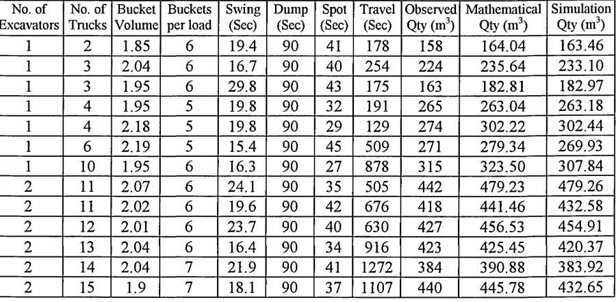
5.14.2 Comparison o f results between mathematical and simulation models...161
5.14.3 Experimental conclusions...163
5.15 Summary and conclusions to chapter...164
6 CONCLUSIONS AND RECOMMENDATIONS...167
6.1 Introduction...167
6.2 Contribution to knowledge...168
6.2.1 Critical Factors...169
6.2.2 Road construction specific model...170
6.3 Recommendations for Future w ork... 172
References... 174
Table of Figures
F ig u r e 1 P la n n i n g te c h n i q u e s u s e d b y c o n t r a c t o r s in t h e UK a n d US... 9
Fig u r e 2 Ty p ic a l Ba rc h a r t... 9
Fig u r e 3 Ex a m p l en e t w o r k...11
Fig u r e 4 Ac t iv it y Cy c l ed ia g r a mo fe x c a v a t o ra n dsin g l et r u c kt y p e... 19
Fig u r e 5 Ev e n tb a se dt r u c ka r r iv a la n dd e pa r t u r er o u t in e s... 21
Fig u r e 6 Sim p l eq u e u e: t r u c kp r o c e s s...23
Fig u r e 7 Pa v e m e n td e t a il s... 37
Fig u r e 8 Dia g r a m m a t icr e p r e s e n t a t io no ft h eex c a v a t io n sc e n a r io...48
Fig u r e 9 Ar t ic u l a t e dt r u c k s’ w o r kc y c l e...50
Fig u r e 10 Ac h ie v a b l eo u t p u tfo rag iv e nn u m b e ro ft r u c k s... 53
Fig u r e 11 Mo d e l l in ge l e m e n t su s e din Mic r oC Y C L O N E ... 54
Fig u r e 12 Ac t iv it y Cy c l ed ia g r a m o ft h ee x c a v a t io np r o c e s s... 55
Fig u r e 13 Pe r c e n t a g ed if fe r e n c eines t im a t e dpr o d u c t io nr a t e s, sim u l a t io nv e r su s MATHEMATICAL MODEL... 57
Fig u r e 14 Ut il is a t io no f Re s o u r c e s...58
Fig u r e 15 Co m pa r iso n o f Ob s e r v e d, Ma t h e m a t ic a la n d Sim u l a t e dp r o d u c t io nr a t e s...60
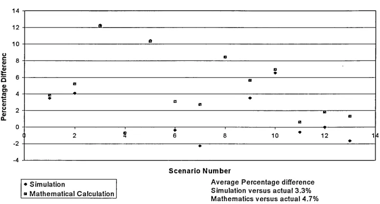
Fig u r e 16 Pe r c e n t a g ed iff e r e n c eb e t w e e nm a t h e m a t ic a la n ds im u l a t io nw h ent h er e s u l t sare COMPARED AGAINST ACTUAL... 61
Fig u r e 17 Ma ine ff e c t s a n din t e r a c t io n sbe t w e e nf a c t o r s...77
Fig u r e 18 Pr o d u c t io nr a t e... 83
Fig u r e 19 Co m p a r is o no f Ou t p u tp e rh o u rf o rsh o r ta n dl o n gh a u l...84
Fig u r e 20 Pe r c e n t a g ed iff e r e n c eino u t p u t... 85
Fig u r e 21 Av e r a g e Ou t p u tm3 pe rh r...86
Fig u r e 22 Pic t u r el e n g t ho ft h eh a u lr o a d... 90
Fig u r e 23 Ut il is a t io no fe x c a v a t o r...91
Fig u r e 24 Pe r c e n t a g ed iff e r e n c eb e t w e e nsin g l ea n dm u l t ipl ec h a in a g e s...92
Fig u r e 25 Ut il is a t io no ft h ee x c a v a t o ra g a in s th a u ld ist a n c eu s in gf iv e D 4 0 0 ’s...93
Fig u r e 26 Diffe r e n c eb e t w e e nsin g l ea n dm u l t ipl ec h a in a g e s...94
Fig u r e 27 sh o w sh o wt h ed iff e r e n c eb e t w e e nsin g l ea n dm u l t ipl ec h a in a g e sast h er a t ioo f CUT TO AVERAGE HAUL LENGTH ALTERS...95
Fig u r e 28 Pr o c e s so v e r v ie w...101
Fig u r e 29 Dif f e r e n tt y pe so fe x c a v a t io ns i t e...102
Fig u r e 30 Sin g l ec h a in a g ec o m m u n ic a t iv em o d e l...103
Fig u r e 31 Sin g l e Ch a in a g e Lo g ic, a... 105
Fig u r e 32 Sin g l e Ch a in a g e Lo g ic, b...106
Fig u r e 33 Sin g l e Ch a in a g e Lo g ic, c...107
Fig u r e 34 Sin g l ec h a in a g ew it hm u l t ipl ee x c a v a t o r s... 108
Fig u r e 35 Sin g l ec h a in a g ed a t ae n t r yf o r m...109
Fig u r e 36 Tr ip l ic a t e Da t a En t r y... 114
Fig u r e 37 Mu l t ip l ec h a in a g ec o m m u n ic a t iv em o d e l... 116
Fig u r e 38 Mu l t ip l e Ch a in a g e Lo g ic, a...118
Fig u r e 39 Mu l t ip l e Ch a in a g e Lo g ic, b...119
Fig u r e 40 Mu l t ip l ec h a in a g e Lo g ic, c... 120
Fig u r e 41 Mu l t ip l ec h a in a g e s...121
Fig u r e 42 Mu l t ip l ec h a in a g ed a t aen tr y f o r m... 122
Fig u r e 43 Ph y s ic a le x c a v a t io n s it e... 125
Fig u r e 44 Tim er e q u ir e dt op o s it io n...126
Fig u r e 45 Lo a d in gt im efo rd u m p e rt r u c k...127
Fig u r e 46 Co m p a c tm a t e r ia lo nt h eb a c ko ft h ed u m pe rt r u c k... 128
Fig u r e 47 Ty p ic a le x c a v a t io nr a t ef o r Ca t 350, Ca t e r pil l a r Pe r f o r m a n c e Ha n d b o o k... 129
Fig u r e 48 Tr a n s p o r t a t io nm o d u l e s... 130
Fig u r e 49 Ha u lr o a d...131
Fig u r e 50 Ha u l-r o a da n im a t io n...132
Fig u r e 51 Ha u l-r o a dd a t ae n t r yf o r m...133
Fig u r e 52 Br id g e s... 136
Fig u r e 53 Br id g e, o n et r u c ka tat im e... 137
Fig u r e 54 Br id g e, o n ed ir e c t io na tat im e... 138
Fig u r e 55 Br id g ea n im a t io n... 138
Fig u r e 58 Tr a f ficl ig h tl o g ic...141
Fig u r e 59 Tr a f f ic-l ig h ta n im a t io n... 142
Fig u r e 60 Tr a f f ic-l ig h td a t aen t r yf o r m...142
Fig u r e 61 Co m m u n ic a t iv em o d e l Dis c h a r g es it e... 144
Fig u r e 62 Dis c h a r g e Sit e, a...145
F ig u r e 63 D is c h a r g e S ite , b...146
Fig u r e 64 Dis c h a r g e sit ea n im a t io n...147
Fig u r e 65 Dis c h a r g e sit ed a t ae n t r yf o r m... 148
Fig u r e 66 Il l u s t r a t io no fh a u lr o u t e...155
Fig u r e 67 Co m p l e t em o d e l...158
Fig u r e 68 Co m p a r iso nb e t w e e n m a t h e m a t ic a la n dst e a d yst a t e sim u l a t io nm o d e l...159
Fig u r e 69 Ut il is a t io no ft h ee x c a v a t o ra g a in s to p e r a t in gp o l ic ie s... 161
1 Introduction
Projects are tendered for and won based on cost, completion date and quality. Producing accurate plans is therefore vitally important. Current planning tools used within the construction industry are static and hence unrepresentative of the dynamic nature of the industry. These planning tools allow neither variation in process duration, nor alteration of resource configurations to be explored.
Simulation allows the exploration of ideas without the disadvantages of experimenting with the real system. Experimenting with the real system has many disadvantages namely; length of time required to perform an experiment, since the time-base is fixed; the lack of control over
environmental factors and hence repeatability of an experiment.
Simulation has been successfully used within the manufacturing industry for allocating both time and resources for the completion of various tasks. Since the manufacturing and construction industries can be considered similar, it is hoped that simulation shall be applicable to both industries. Construction personnel have thus far been reluctant to embrace simulation, perhaps because they perceive each construction project to be unique requiring the development of a complex simulation model. Considering each project as a whole, they are unique. Yet, at an operational level, the tasks are often very similar, e.g. one site might require up to 100,000m3 of material to be excavated while another may require only 1000m3 of
It is proposed that the use of simulation in the construction industry can be increased through the development of generic modules that can be joined together to rapidly develop a working simulation model.
1.1 AIMS OF THE RESEARCH
The aims of this research are as follows:
• Identify where simulation has been utilised within the construction industry.
This research shall be of practical significance to researchers, construction planners and software developers. It will provide a source of reference documenting where simulation has been utilised, and the benefits obtained from applying the technique.
• Establish the reasons for simulation not being widely used in the construction industry outside academia. Propose a solution and select a methodology that shall enable the rapid development of simulation modules for the construction industry.
• Analyse the factors that influence output in a particular sector of the construction industry.
1.2 OBJECTIVES OF THE RESEARCH
The project aims will be achieved through these objectives.
• Undertake a critical review of the literature revealing where simulation has been applied in the construction industry and the type of modelling methodologies employed.
• Develop simulation models of construction processes using the most popular modelling methodologies from both the construction and manufacturing industries.
• Establish a methodology for the development of specific construction activity modules.
• Determine the main effect and interaction between factors using the experimental technique factor analysis.
• Examine the significant factors to determine how Output is affected by modelling a system in varying degrees of detail.
1.3 STRUCTURE OF THE THESIS
Chapter 1 Introduction
The contents of this thesis are chapter outlined, together with the aims, objectives and scope of the research.
Chapter 2 Literature Review
The variety of planning tools adopted by the construction industry are documented, with the limitations of each outlined. The ability to model complex interactions between resources using simulation enables some of the disadvantages associated with traditional
planning tools to be overcome. A number of construction processes have been modeled using discrete event simulation. Commonality between these process characteristics is highlighted with a
construction process identified for the application of simulation. The academic community has to a limited extent, explored simulation and demonstrated some of benefits that simulation can bring to the
construction industry. Yet, the construction industry has not embraced this technology, the reasons for this are documented.
Chapter 3 Selection of simulation methodology
determine a suitable simulation methodology for the development of simulation modules for the construction industry.
Chapter 4 Analysis of significant factors
For the construction industry to embrace simulation, it must be easy for an individual, not wholly conversant with the art of simulation, to develop models and assess different resource configurations for a large number of scenarios. Simulation modules that can be joined together is one approach for solving this problem. The significance of each factor, whether it has a main effect or interacts with other factors, is established using factor analysis. Further experiments were performed on significant factors to determine an appropriate level of detail for the modules. This prevented resources from being wasted through including insignificant factors in the modules.
Chapter 5 Development and use of generic modules
Simulation modules can be developed once a simulation
Chapter 6 Conclusions and recommendations
The suitability of using simulation to plan road construction earthworks has been determined. The feasibility of developing simulation modules of construction operations and the significance of each factor has been established. To increase the number of construction scenarios that may be modeled using the modules it is recommended that additional modules be developed using the methodology presented within this thesis.
1.4 SCOPE AND LIMITATIONS OF THE RESEARCH
2 Literature Review
2.1 INTRODUCTION
This literature survey contains a review of papers, books and thesis relating to planning of construction activities. It examines how construction
projects are currently planned and controlled. The drawbacks of using static planning tools are highlighted, together with the advantages of using a dynamic planning tool such as discrete event simulation.
There are only a few documented applications of simulation within the construction industry; these are examined later within this chapter. Hence, it was necessary to examine other industries that have benefited from using discrete event simulation to establish what modelling techniques are
employed.
Simulation may reduce the number and magnitude of delays. This chapter contains a general review of simulation identifying where it has been applied within the construction industry. The characteristics of these activities are noted enabling new operations within the construction industry to be identified.
2.2 PLANNING TECHNIQUES.
Within the construction industry, project planning is vitally important. A good plan provides the opportunity for contracts to be won in the
“The results of a well planned carefully monitored and controlled contract reflect directly on the profitability of the contract and the company.” Wijesundera (1989).
If the accuracy of planning construction operations can be improved, then all concerned with the project shall benefit. The current economic climate necessitates the submission of tenders on a near zero profit basis. Hence,
any unexpected delay significantly undermines the viability of the project necessitating the investigation of planning techniques within the
construction and other similar industries.
2.2.1 TYPES OF PLANNING TOOLS.
It is difficult to consider all of the possible construction sequences through which a building may be erected without the aid of a suitable planning tool. To assist in the management of construction projects there are several tools currently available; Bar-Chart, Critical Path Method (CPM) and Line Of Balance (LOB) to name but a few.
Figure 1 Planning techniques used by contractors in the UK and US.
Source: Aouad (1994).
2.2.2 GRAPHICAL MODELS:- THE GANTT (BARI CHART.
The Gantt chart, more commonly known as the bar-chart, was developed by Henry Gantt around the 1900’s. A Gantt chart consists of a list of activities recorded against a time scale with both start and end dates given for each activity. The duration of which is usually given in terms of half days, days or weeks and is represented by a continuous bar. An example of a typical bar-chart is given in Figure 2.
Operations ItemNo. 17 24 1Sep 8 15 22 29 5 12 19 26 3 10 17 24Oct 0 Dec 37 38 39 40 41 42 43 44 45 46 47 48 49 50 51 Formation &
Capping 31
Complete 32
drainage, ducts, subbase channels
Surfacing 33
Figure 2 Typical Bar chart
facilitating tighter planning and control. Figure 2 shows that drainage should start after the formation and capping operation has started.
However, the interdependencies of activities are not explicitly defined, i.e. could drainage start any earlier, if so, by how much and would starting drainage earlier reduce the overall project duration? To enable questions like these to be answered linked bar-charts can be used.
2.2.3 LINKED BAR CHARTS.
Linked bar charts Archibald (1967) were developed to establish which processes/activities must lead or follow one another. This enabled
activities that were critical and those with float to be identified so that the effect of completing a given sequence of activities late could be
anticipated.
Another adversary of the bar-chart, Archibald (1967) stated that bar charts are seriously flawed; ’the inability to reflect uncertainty, or tolerances, in the duration times estimated for the various activities. In contemporary management this deficiency can be critical.'
However, it should be bom in mind that Archibald was a champion of both Critical Path Method (CPM) and Program Evaluation and Research
Technique (PERT).
2.2.4 NETWORK MODELLING TOOLS
The advent of powerful computers in the mid 50’s and the increased desire to complete projects on time and within budget led to a new generation of planning tools.
• Critical Path Method (CPM) was developed in 1957.
• Project Evaluation and Review Technique (PERT) were developed independently, but around the same time as CPM.
Kelly developed one of the first network modelling tools, CPM, originally to improve the planning and scheduling for the construction and
[image:24.613.109.464.318.522.2]maintenance of chemical processing plants.
Figure 3 Example network
Clearly, CPM is an improvement upon the bar-chart when there is a requirement for activities that are critical to be determined. However, Adrian (1973) states that the duration of activities recorded in CPM are deterministic and hence inappropriate. It is clearly inappropriate to consider activities as possessing durations that are deterministic, since activity durations are dependant upon many factors including; weather, labour availability/experience and equipment reliability. It would be more realistic to assume that the durations of activities are variable (stochastic). A PERT model assumes that activity durations are stochastic.
2.2.5 PERT
In 1957, management consultants Booz, Allen, and Hamilton developed PERT for the US Navy Special Projects Office. The aim of project PERT (Program Evaluation Research Task) was to develop a tool that would provide its management with:
-• Information on the progress to date and the outlook for accomplishing the Fleet Ballistic Missile (FBM) program,
• Measure o f the validity o f established schedules for the optimum accomplishment of total program objectives,
• Predict the impact of actual or proposed changes in plans on total objectives.
The duration of each activity in a PERT model is based upon past
experience. A minimum, maximum and mean duration is obtained for each operation and incorporated into the model in the form of a stochastic,
Despite the widespread acceptance of CPM and PERT, schedule overruns continue to be a major problem. One possible reason is that network schedules calculated with CPM or PERT do not provide adequate
information regarding the potential for schedule overruns. That is, CPM gives only a single number, which is intended to be the duration of the project. PERT is but a slight improvement in that it attempts to evaluate the probability of a project’s duration by giving the expected completion time. Additionally, the PERT method sums the variance of the activities along the path used to calculate the expected completion time in order to express a measure of risk to the project duration.
'Although PERT introduces elements of probability into the calculations, PERT consistently underestimates project duration. The principal cause of this underestimation is a condition known as "merge event bias." Briefly, merge event bias occurs when several paths converge on a single node.' Halpin (1992).
Kavanagh (1985) summarised the findings of Ashley (1980), Birrel (1980) and Peer (1974). 'CPM/PERT places emphasis on minimising the total duration of a project and therefore makes the fundamental, unrealistic assumption that resources are unlimited and centrally controlled. The contractor, however, is primarily interested in minimising the resource input and maximising resource utilisation.'
CPM and PERT are not used exclusively by the construction industry; indeed the manufacturing industry has used these techniques for many years. However, the drawbacks inherent to these techniques have led to the investigation of other planning tools. One of the more successful tools for planning complex processes in the manufacturing environment is
2.3 WHAT IS SIMULATION?
2.3.1 SIMULATION AND MODELLING PHILOSOPHY
Simulation and modelling are widely used to describe a whole manner of applications from finite difference analysis to flight simulators. The first stage in this research project is to define precisely what is meant by the terms discrete event simulation and modelling. The Oxford English
dictionary does very little to clarify the meaning of these terms.
Discrete; - Discontinuous, consisting of distinct parts.
Event; - Anything which happens, any incident, occurrence or
result.
Simulate; - Pretend to be, have, or feel; Imitate or counterfeit;
Reproduce the conditions of (a situation etc.); Produce a computer model of (a process).
And to model; - Representation in 3D of an existing person or thing of a proposed structure, esp. on a smaller scale; Simplified description of a system etc., to assist calculations and predictions; Figure in clay, wax etc., to be reproduced in another material; Particular design or style, esp. of a car.
When reading the literature on simulation it became apparent that the word simulation means different things to different authors. The Author of 'Cranes, Concrete, Construction...& Computers', Tarricone (1992), believed simulation to be that of 3D visualisation, Lansley (1981) used simulation as a gaming tool for modelling management strategies. While McCahill
available resources. Both are totally valid interpretations; however in this thesis, it is the models documented by Dennis McCahill rather than Paul Tarricone that are considered as discrete event simulation.
Construction and manufacturing have many similar operational
characteristics. However, best practices; ‘Just in Time’ and ‘Material Requirement Planning’, developed in manufacturing have rarely been used in the construction industry. Among the many best practices that exist, Halpin (1993), argued that computer simulation would provide an excellent opportunity to improve output, reduce cost and shorten lead times in the construction industry. For example, at present, conventional project planning tools are used to plan and manage construction projects. These 'static models', however, do not consider the dynamic nature of
construction processes with resources allocated to activities on an
aggregate basis. These over-simplified models often provide less accurate performance data hence managers and planners make ill-informed
decisions. Consequently, project targets may be missed and additional expense incurred.
In contrast, 'dynamic models' such as computer simulation can take account of time variations (as occur in real construction projects) with the
2.3.2 W HY SIMULATE?
Nunnally (1981) and Halpin (1992) indicated that one particular reason for applying simulation in construction was because of the limitations of current planning tools, stating that “because of the complexity of interactions among units on the job site and in the construction
environment, queuing models can be applied to only a limited number of special cases.” Thus simulation, through its ability to model the dynamic characteristics of operations as evident in manufacturing, offers the
potential to be an improved planning technique over existing tools, particularly where the processes are repetitive.
One could of course perform the majority of desirable experiments on the real system rather than incur the cost of generating a computer model, but in doing so there are many dangers to overcome. Robinson (1994) gave several reasons for this.
• Cost: to assess the impact of utilising additional machinery would necessitate incurring the cost of renting and installing machinery not to mention the cost of training operators.
• Repeatability: a particular phenomenon may seldom occur, perhaps only when several separate conditions are present, however the condition may seriously affect the operation of the facility.
• Control of the time base: activities seldom occur at an appropriate speed to allow detailed analysis. The operation may be performed too quickly in the case of a bottling facility, or too slowly when examining the possible throughput of a car paint spray booth. A computer model allows the speed of the activity to be performed at a user-defined rate allowing closer analysis of the system.
• Legality and safety: experiments are performed remote to the system eliminating disruption to the facility, confusion and associated reduction in safety that changing work patterns can cause.
Of course, a system could be represented using a mathematical model, however the dynamic and transient effects, non-standard distributions, and interaction of random events can not be determined, Robinson (1994).
2.4 ACTIVITY CYCLE, EVENT VS PROCESS BASED SIMULATION
2.4.1 INTRODUCTION
Although simulation is an appropriate tool for modelling construction activities, there are only a few documented applications, in comparison to the manufacturing industry where many applications have been
documented. Where simulation has been applied within the construction industry, it has been done so using the activity cycle methodology where as the manufacturing industry tends to utilise process based methodology. Thus the following section discusses the various simulation methodologies available.
2.4.2 SELECTION OF M ODELLING M ETHODOLOGY
There are three main types of modelling methodologies or ‘word views’ Activity, Entity and Process based. Each of which represents a
compromise between how well the real world can be modelled, the ease of model building or their computational efficiency, Carrie (1988).
2.4.3 ACTIVITY CYCLE M ETHODOLOGY
The activity cycle methodology is most commonly used for modelling construction operations. With academics; Oloufa (1992), Ioannou (1992), Vanegas (1994) and Huang (1994) each developing their own simulation packages based on this methodology.
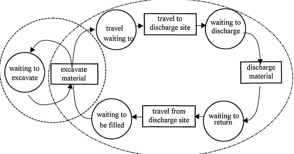
• ‘Each type of entity has an activity cycle • The cycle consists of activities and queues • Activities and queues alternate in the cycle • The cycle is closed
• Activities are depicted by rectangles and queues by circles or ellipses’, Carrie(1988).
Thus the simple activity of excavating and hauling material may be represented as Figure 4.
travel to
discharge site waiting to discharge travel
waiting ti
discharge material waiting to \ /
excavate / j excavatematerial
travel from discharge site waiting to
be filled
[image:32.614.70.542.243.491.2]waiting to return
Figure 4 Activity Cycle diagram of excavator and single truck type.
A circle is used to represent an idle state with a rectangle to represent a busy state. Thus the excavator can either be idle, waiting for a truck or busy filling it. Whereas a truck can be waiting for the excavator, being filled, waiting to travel to the discharge site, travelling to the discharge site, waiting to discharge the material, discharging the material, waiting to
Although it is considered to be conceptually easier to develop activity cycle diagrams, Pidd (1994) commented that ‘the main advantage of this
approach [activity cycle] is that it supports rapid program development. The main snag is that, without considerable effort, it is very difficult to model complex systems.’
2.4.4 EVENT-BASED APPROACH
Event based simulation packages, such as SEE-WHY and GASP consist of event routines, where an event routine describes the operations in which entities engage when the system changes state, such as the beginning or the end of an activity. As an example, take the event of an articulated truck arriving at an excavator and joining a queue on a first in first out basis, in an event based model there are two stage changes:
• The arrival of the truck
• The end of service, i.e. the departure of the truck.
From Exexutive
From Exexutive
No No
Ex cavator free
Yes Yes
To Exexutive To Exexutive
Schedule end event G enerate service time Schedule next
arrival
Schedule end of service
Release Ex cavator
Increase queue by 1 G enerate
service time Generate time of next arrival
Free Ex cavator
[image:34.613.90.475.39.418.2]Arrival of Articulated Truck event routine End of service event routine
Figure 5 Event based truck arrival and departure routines
Arrival o f next articulated truck: if the excavator is free and no queue exists, it is immediately loaded. Otherwise the truck joins a queue.
End o f service: the truck leaves the excavation area. The excavator serves the next truck if there are any waiting in the queue. If there are non
waiting, the excavator becomes idle.
• They tend to produce smaller program segments for activities than would be the case for events.
• An analyst need not be too concerned about the sequence of activities at each event - since this is sorted out by the executive in the activity scan. Hence the approach to programming is more structured making it easier to modify existing models, which is particularly important when developing large and complex simulation models.
2.4.5 PROCESS BASED
The third simulation methodology is the process based approach, which “views the simulation in terms of the individual entities involved, and the code written describes the ‘experience’ of a ‘typical’ entity as it ‘flows’ through the system.” Law (1991, p. 13). Thus in earthmoving, the entity is the material and the experience is the processes that the entity is exposed to, e.g. the method that is used to excavate, haul or discharge the material. This differs from activity cycle simulation where the focus is on the use of resources in order to perform a sequence of activities.
In process based simulation the progress of each entity continues until it is blocked or delayed for some reason. Generally two kinds of delay are considered.
Unconditional delays, e.g. excavation time. In these, the entity remains at the same point in its process until the pre-determined excavation time has elapsed.
Thus the simple activity of excavating material may be represented as Figure 6.
From Executive
Yes
No
No
Yes
T o Ex ecutive Queue Exists?
Ex cavator "vj?ree'?^
Schedule end of service Generate time of next arrival
Generate service time
Add Truck to Queue Schedule next
arrival
Free excavator
Wait until head of queue and ex cavator free
Engage excavator. Remove truck
from queue
An articulated truck arrives in the excavation area. If there is a queue then the truck joins it and conditionally waits for the excavator to become available. When the excavator becomes available the truck engages it and is unconditionally delayed while it is filled. Once full the truck leaves the excavation area freeing the excavator.
2.5 COM PARISON OF M ETHODOLOGIES
Although it is easier to develop a simple simulation model using activity cycle as opposed to the process based approach, as the complexity of the model increases it becomes increasingly difficult to model using activity cycle methodology, and ‘in most cases they cannot include the full complexity of a system being simulated’, Pidd (1989).
Sergen (1995) observed that ‘activity cycle diagrams only contain a few symbols, they cannot, in most cases, fully represent the complexity of the system being modelled. It is difficult to express the logic and the rules of the system, sometimes called process strategies, without using dummy cycles.’ Pidd (1992) concurs with this view stating that; “There are systems which do not easily fit the activity cycle notion - though
enthusiasts would argue that they can be made to fit. One such type of system is where the interruption of an active state may occur before it reaches its scheduled termination.” This is similar to what can happen to a truck as its progress may be interrupted by congestion of traffic lights or even roundabouts.
simulation methodology. He observed that there is a trend for the cost of computers to keep falling where as the cost of skilled labour shows no sign of dropping. Hence, it would seem appropriate to concentrate on methods that reduce the length of time to produce a working, valid simulation model by easing the task of the programmer.
Finally, the results attained through modelling a given system should be the same irrespective of which methodology is employed and what ultimately maters is the ease with which a model can be constructed, and that is dependant upon the software employed, which is examined in section 3.3.
2.6 OVERVIEW OF W HERE SIMULATION HAS BEEN USED IN CONSTRUCTION
When simulation has been applied to construction processes, it has been documented almost exclusively by academics. This could be because academics document and publish substantially more than their industrial counterparts, or that the construction industry views simulation as an abstract tool, only to be undertaken as an academic exercise and bearing little relevance to the outside world. Alternatively it could simply be explained by the fact that industry does not yet appreciate how to exploit the potential of simulation.
The majority of the research into using discrete event simulation within the construction industry emanates from North America. This is principally because the most noticeable champion of simulation in the construction industry is Professor D. W. Halpin who is based at Purdue University, West Lafayette. His studies began with the ‘investigation of the use of
Halpin realised that the construction industry considered process-based simulation to be an abstract tool with little correlation between its modelling elements and construction processes and consequently developed CYCLONE. He considered the activity cycle based
methodology, upon which CYCLONE is based, to represent construction activities more closely than process based simulation. Later Lluch (1981) under his guidance developed a microcomputer-based version of
CYCLONE, called MicroCYCLONE. More recently a windows based animated front-end was developed called DISCO, Huang (1993).
Another of Halpin’s researchers AbouRizk, supervised Sawhney (1994) and the development of the AP modelling methodology, which
recommends that the method of simulating construction processes could be simplified if a model environment was develop consisting of eight basic components:
1. A database to store resource attributes.
2. An atomic model library that includes all types of resources for a specific type of construction project.
3. A user interface that allows the user to specify required resources, project related resource attributes, and other project information.
4. A module to convert physical site conditions to simulation information, e.g. computing the duration of a construction process from the physical site conditions.
5. An atomic model generation module which can combine resource attributes and project-related information with atomic models in the library to produce project specific atomic models.
6. A knowledge-based module which can identify and generate proper linking structures to suit the atomic models.
8. An interface which can call the selected simulation language and allow the user to experiment with the generated model.
Shi (1994) also proposed the development of atomic models consisting of resources and operating processes which are stored in model libraries using object oriented representation technologies. However, in order to develop the libraries he considered that several issues need to be resolved including defining and designing the atomic model to be included in the libraries, together with the mechanism for assembling models from the atomic elements. From his research he also concluded ‘that for equipment intensive applications such as earthmoving, simulation can be applied at very little cost if the modelling environment is consistent with the way planners model their systems.’
Ioannou (1996) also recognised the limitations of the simulation packages available and adapted and enhanced MicroCYCLONE to produce a
simulation-modelling package called Stroboscope. Stroboscope differs from its predecessor by allowing the use of attributes, which are extremely useful. They enable the characteristics of say, excavated material to be retained. Making it possible to change the amount of material that may be compacted depending upon the type of material excavated. Ioannou
demonstrated the functionality of Stroboscope by developing models of and establishing which of two bridges would be the most cost effective to
purchase.
One of the more unusual pieces of research was undertaken by AbouRizk (1993). Unlike previous academics, where the applications were
(ATU) Bridge Engineering Branch, and Northern Steel Inc. (NSI). The disagreement stemmed from a complexity claim accruing to additional labour amounting to $236,000. A simulation model was built to compare the original working method with that of the required proposal, caused by an amendment to the design specification. The model was a success, with the output considered unbiased and as such, it was deemed that a justifiable excess claim should be between $124,523 - $130,549.
Hajjar (1997), also appreciated that there was a gap between simulation tools and the abilities of construction planners to use simulation and
suggested the development of simulation models could be simplified using a visual object-oriented environment. To this end special purpose
simulation tools; AP2-Earth, Hajjar (1997) and CRUISER, Hajjar (1998) were developed using object-oriented techniques. Object-oriented
techniques simplify module development through the notion of encapsulation. Where all of an entity’s properties are set within the definition of the object, Joines (1998). With one object communicating with another by passing messages. Thus additional modules can be created without requiring an original object to be modified.
Although early researchers used activity cycle methodology, e.g. Halpin (1973), recently some research has been performed using process based simulation Gonzalez-Quedo (1993) and Hajjar (1997). The following chapter therefore investigates the suitability of each methodology for modelling a particular construction scenario.
Tools Modelling Methodology
MicroCYCLONE Activity cycle
DISCO Activity cycle
STROBOSCOPE Activity cycle
CIPROS Activity cycle
SLAMII Process Based
AP2-Earth Object oriented
CRUISER Object oriented
Table 1 Simulation packages used to model construction operations.
Even thought the application areas appear to be diverse, upon closer inspection it became apparent that previous simulation research typically falls into one of two categories, earthmoving or placement of concrete. These two categories possess particular characteristics that make them suitable to be modelled using simulation.
• Systems are modelled at an activity level, involving the allocation and utilisation of resources.
• The processes are repetitive, usually lasting several hours, • The equipment used or material handled is expensive,
• The type of machinery used and their processing times are predicable.
Not only is it important to consider how and where simulation has been applied in the construction industry but also to establish activities that have either been infrequently modelled or wholly overlooked.
significantly from one day to another. An employee will work at different rates depending upon, fatigue, lengths of the day, weather, morale and of course the operatives’ ability and willingness to perform the task. The advantage of accurately estimating the time required to complete small tasks involving complex interactions are currently outweighed by the time required to develop a useful model.
It is however possible to model alternative methods of construction,
establishing the most efficient equipment configuration. As the accuracy of the data required for a comparative study is significantly less than that required for accurately predicting production duration, Shannon (1992).
In comparison to the manufacturing industry where there are hundreds of applications documenting the use of simulation, there are relatively few examples within the construction industry. Indeed, when Shannon (1992) addressed that year’s Winter Simulation Conference the construction industry was noticeably absent from the application domains listed within his paper.
2.6.1 USE OF SIMULATION WITHIN THE CONSTRUCTION INDUSTRY
The majority of the articles reviewed in the literature survey were written by academics, to demonstrate how simulation could in theory be used within the construction industry. Only a few industrial applications of where simulation has been applied have been sighted.
The lack of documentation supporting the hypothesis “simulation is utilised within the construction industry” led to the supposition that this industry does not use simulation. However, industrial practitioners seldom have the time, or the inclination to document their use of a particular management tool, therefore it was necessary to consult various employees within construction companies to establish whether simulation is being utilised. To this end a preliminary questionnaire was devised, delivered and the results evaluated.
Preliminary Questionnaire
It was considered that a questionnaire would enable a large number of construction companies to be contacted not only to assess which, if any used simulation, but also those that might wish to develop and enhance the planning and allocation of resources. It was anticipated that companies receive numerous requests for assistance from researchers, students and school children. Thus, to increase the response rate the questionnaire was directed towards an individual, rather than speculatively to a department within an organisation. Also, the number of questions posed was kept to a minimum and contained within two pages.
Aim of each question
Understanding whether planners perceive material to arrive in the correct location in the correct quantities, indicates whether they are content with their method of planning and allocating resources, and hence their
willingness to investigate an alternative method. One of the benefits of simulation is that it facilitates experimentation. If planners consider
altering such a fundamental factor as the material schedule impossible, then it is unlikely that they would be willing to alter other parameters, thus, the benefit of simulating a system would be reduced.
As stated earlier, it is quite possible that simulation is being utilised within the construction industry without the outcomes of their study being
publicised. Thus the respondents were asked whether they were aware of simulation being utilised, if so how and where.
Selection of respondents
To obtain an indicative answer to each question, a random sample of thirty construction companies were alphabetically selected from a construction design and build journal. To maximise the response rate, each company was contacted by telephone to obtain the full name and address of the chief planning engineer. Of the thirty companies contacted twelve
Questionnaire Results Y/M ox 00 0s oo
(Site staff 8%, Site agent 8%) Don't Know
25% 8% 8% Other 25% 25% No o x 00 0s00 50% 25% 67% 25% 92% 84% Yes 75% 75% 84% 100% 84% 84% 50% 50% 33% 67% 0s00 ox 00
Is the Site Manager responsible for materials management? Does the Site Manager decide where material is located? Do you ever consider fixing material upon delivery? When buying in bulk, is it possible to stagger delivery?
Does staggering delivery eliminate double handling of the material? Does the Site Manager determine the delivery schedule?
Does your company use a central material store on site?
Does the location of material significantly affect the cost of storage? Do you use intermediate stores?
Are there any specific problems in relation to material handling/location that you feel should be addressed?
Does you company utilise simulation in any manner?
Is the storage of material currently simulated to minimise double handling ?
Conclusions drawn; preliminary questionnaire
The vast majority of the respondents considered the site engineer to be responsible for scheduling and allocating materials. Since it is the site engineer that will ultimately benefit from being able to experiment with different resource configurations, he shall be contacted in the first
instance both to demonstrate the benefits of simulation and to obtain data.
The full potential of simulation can only be realised if it is possible to alter the operation of a facility to maximise certain performance
parameters. It would appear from the responses that it is possible to alter performance parameters, specifically the arrival of material, hence it is possible that output may be improved through the application of
simulation.
Sixty-seven percent of the respondents consider that the planning and allocation of material could be improved. Had the respondents
considered the planning and allocation of material could not be improved then there would be little reason for an alternative planning tool to be developed as it would probably never be used.
Two of the respondents claimed that the company they were employed by utilised simulation. To ascertain where and how the respondents were contacted by telephone. In each case when pressed, it transpired that they either perceived simulation to mean 3D visualisation/animation, or they had heard that simulation was being employed but were unable to
Conclusion
The respondents acknowledge that the planning techniques currently employed within the construction industry provide a less than optimal solution for planning the allocation of material. However the high response rate of sixty percent does indicate a desire within the
construction industry to develop and improve the methods of planning currently employed.
The results of this preliminary survey indicate that simulation is not being used within the UK construction industry. These finding concur with those of Aouad, when he surveyed the top 100 contractors in the UK and the top 400 contractors in the US. Aouad (1994) also concluded that simulation has not received greater attention because:
“ • it is too sophisticated and inaccurate
• there are too many variables in output and weather • there is insufficient time available to build models • planning a contract is an individual operation
• computer models require large amount of data input • they are too costly.”
Gonzalez-Quedo (1993) also gave reasons for the less than popular
acceptance of simulation claiming that it is due to the quantity of learning involved, coupled with the “lack of confidence in the results of unproved techniques” and the “failure of academic researchers to provide
practitioners with accurate, easy-to-use, and proven techniques”.
simulation, it is proposed that a series of standard modules are developed. It envisaged that these modules may be connected together to form a working model requiring little validation and testing before experiments are performed and results obtained. However, before standard models are developed a suitable area within the construction industry must be sought.
2.6.2 PROPOSED APPLICATIONS OF SIMULATION.
There appears to be a requirement for a flexible tool that is capable of overcoming the problems associated with the complex, uncertain and highly volatile construction environment by assisting the decision maker, through making it possible to generate and analyse different courses of action and their likely outcomes. It is generally believed that computer- based simulation can provide such a solution. Both Ibbs C.W. (Ed)(1985) and Tommelein (1994) endorsed this view.
Ghassan Aouad and Andrew D.F. Price (1994) ascertained nine areas where expert systems and simulation techniques could be applied to assist in planning construction processes.
• Standard works (i.e. warehouses, factories)
• Small development and temporary works
• Large contracts with a large number of subcontractors
• Different cranage applications and use or re-use of formwork could be modelled
• "What if?" scenarios are easy to assess
• Problematic scheduling areas can be modelled
• Activity breakdown structure
• Manpower analysis
Simulation can be an extremely useful tool providing useful results can be obtained without requiring the input of excessive quantities of information and the cost is justifiable.
2.6.3 USE OF SIMULATION IN ROAD CONSTRUCTION.
Cutting Non-pavement verge
Hardsholder, hardship or
Slope
Carrageway
Concrete Channel
Surfacing
Road base
Sub-base
Capping
[image:51.612.64.494.233.538.2]Drain
Earthworks Outline
Figure 7 Pavement details
One of the most resource intensive and hence expensive operations are earthworks. Earthworks concern the operations surrounding the removal of material generally referred to as cut, or its placement, which is
generally referred to as fill. Excavators or scrapers tend to be used to remove material with trucks or motor-scrapers used to haul the material while discharged material is compacted using bulldozers or vibrating rollers. The performance of each operation is influenced by many factors. Excavation rate may vary depending upon the characteristics of the material being excavated or the conditions along the haul-road, such as congestion or bridges may impede the transportation of material. Hence several researchers have attempted to apply simulation to the construction industry to increase the quality of estimates and resource utilisation.
Huang (1994) investigated transient behaviour in earthmoving using simulation. From his experiments he ascertained that the maximum effect of transient behaviour was to reduce output by 1.3%. However, the scenario modelled was extremely simple involving minimal interaction between resources, and no congestion along the haul road.
Alkoc (1993) simulated the placement of concrete, however the model had its limitations. Although the movement of the distance the trucks must travel increases, the software was unable to model this as a
of material laid at each chainage was constant thus the advancement of the paver was uniform, which is unlike earthworks where the quantity of material excavated from each chainage alters.
In ‘Automated construction-simulation optimisation’ AbouRizk (1994) used simulation to automatically optimise several performance
parameters: production unit cost, production rate, and resource utilisation. However, the models were aimed at mining and were unable to optimise all three parameters simultaneously.
Good communication is paramount if the maximum benefit can be obtained from simulating construction processes. Communication ‘can be greatly enhanced if the building elements describing the model are not generic but rather a graphic representation of the resources used at the site’, Oloufa (1992). Models consisting of circles and boxes are more abstract than a map with realistic pictures. ‘Cyclone model uses generic icons that are unfamiliar and hard to understand for the members of the construction team.’ Oloufa (1992). This iconic representation limits the communication of a simulation model and restricts its value.
Amir Tavakoli (1985) appreciated that there was scope for using
simulation within road-construction and recognised that industry would not use simulation unless models can be quickly and easily be developed by none simulation practitioners. To this end, he developed three models based on the MicroCYCLONE simulation package. These models
The three models were:
• Face shovel, loaders, haul trucks and a dozer, • Scraper, pusher, excavation crane and truck dozer, • Crane, trucks, and spreader unit.
However, the models could not be easily modified to incorporate other factors and hence are inappropriate for modelling other sites.
In parallel to the research undertaken and documented within this thesis, researchers at the Universities of Michigan, Alberta and Edinburgh have developed software for the construction industry.
Ioannou (1996) developed STROBOSCOPE based on the activity cycle paradigm and demonstrated its application for moving large quantity of material in the construction of a dam. The software is abstract using iconic symbols not representative of the construction site. No account is made for congestion along the haul road, this is especially important since two different types of trucks are made available. Two years later
Martinez (1998), co-author of the above paper stated that
STROBOSCOPE demands “a level of training that is beyond the scope that which can be found in most current practitioners.” Hence, Martinez developed ‘Earthmover’ to overcome some of the limitations of
STROBOSCOPE by creating a visual front end using VISIO.
Shi (1998) developed a simulation platform enabling models to be constructed from a set of predefined modules. His work was again specifically aimed at developing a simulation package for large-scale earthmoving founded upon the modelling methodology documented by AbouRizk (1995). In essence, the methodology aims to develop a simulation model based upon selecting the required equipment and project information for the operation.
The simulation models that are developed are constructed in several stages. An activity cycle diagram is constructed, equipment is selected from a database, project specific data is entered, R-processes are
generated and finally the model is generated. Although the end product of both pieces of research is similar, the methodology for reaching the goal is very different. Within his research the factors that have been included have been selected by intuition rather that experimentation. Detailed analysis of the factors has not been undertaken; specifically the significance of changing haul duration during excavation has not been examined.
Smith (1995a) undertook the only research focusing specifically on road construction. Smith (1995a) within his research, six factors affecting earthmoving for road construction were examined; number of trucks, passes per load, mean and variability on load time, mean and variability on travel time. A simulation model incorporating those factors was developed. However, by his own admission excavation could only take place using a single excavator and a single class of truck. Further
examination of his thesis identified that the haul road was always simple in nature, with the transportation of material never hindered by
significance of several factors, which occur in practice, has not been established.
2.6.4 JUSTIFICATION OF CURRENT WORK
Traditional planning techniques are often inadequate. They neither provide information on critical path variation nor critical activities. The value of factors, e.g. rolling resistance, may change over time and affect the programme of work. Therefore, any planning tool must be quick to use and the results easy to interpret.
It has been observed that 'there has been a substantial increase in the number and magnitude of delays in the construction of highway projects' Herbsman (1985).
AbouRizk (1994) stated that “simulation has great potential in advancing construction planning; however, more research needs to be done to make it an easy-to-use tool for the practitioner.”
Simulation was selected because it has a proven record for benefiting the manufacturing industry. It is hoped that by both demonstrating the benefits of applying the technique and providing a framework for implementation the construction industry may reap the rewards already experienced within the manufacturing industry.
The majority of the models have been developed using the activity cycle methodology, however this does not imply that the activity cycle
either Professor Hatpin or one of his students. In which case the students may have been biased towards a particular methodology. Since the construction industry has not embraced this methodology, the suitability of three simulation methodologies were examined; activity-cycle, event and process based simulation. From the literature it appears that process- based simulation is better suited for modelling the complex interactions between the resources found on construction sites.
It is also apparent, from the literature, that simulation is most often applied in areas that are resource intensive, repetitive and cyclic.
However, models involving a significant number of interactions between humans tend not to be developed.
Earthworks for road construction and mining have many similarities; these together with the differences are discussed later. Road construction and mining involve activities that are resource intensive, repetitive and cyclic, with the focus of any plan being around the equipment rather than the labourers. It should therefore be possible to accurately simulate earthworks for road construction.