Error Rate Performance of Digital Chirp
Communication System over Fading Channels
Mohammad Alsharef,
Member, IAENG,
Abdulbaset M. Hamed,
Member, IAENG,
and Raveendra K. Rao
Abstract—In the paper, new and easy-to-compute closed-form expressions for average symbol error probability of digitalM-ary chirp communication system impaired by additive white Gaussian noise and fading are derived. Three fading environments, Rayleigh, Nakagami-m, and generalized-K, that represent most practical wireless channels are considered. The closed-form expressions derived are then used to illustrate the performances of 2-,4-, and 8-ary chirp systems as a function of average received signal-to-noise ratio (SNR), modulation and fading environment parameters. The proposed mathematical analysis can be easily used to design an efficient and reliable M-ary chirp communication system for application over fading channels.
Index Terms—Chirp modulation, Rayleigh fading, Nakagami-mfading,KGfading, Average error probability.
I. INTRODUCTION
C
HIRP modulation, also known as a linear frequencymodulation, can be viewed as a type of spread spectrum signaling technique in which a carrier is swept over a wide-band during a given data pulse interval. This spreading tech-nique produces a signal whose bandwidth is much wider than the information bandwidth. Because chirp signals possess properties that are useful in wireless communication, they are expected to be utilized in a variety of future communication systems. In particular, the growing interest in chirp signals is due to the advances in Surface Wave Acoustic (SAW) technology, which offers a rapid close-to-optimum method for both generation and correlation of wide-band chirp pulses [1]. In 2007, IEEE introduced Chirp Spread Spectrum (CSS) physical layer in its standard 802.15.4a [2]. Furthermore, single-chip transceivers for wireless communication in the industrial, scientific, and medical (ISM) band have been developed and are commercially available [3]. In [4],
Al-sharef and Rao have proposed M-ary signaling technique
for chirp modulation and have evaluated its performance over Additive White Gaussian Noise (AWGN) channel for coherent and non-coherent detection. Gupta, Mumtaz, Zaman and Papandreou-Suppappola [5] have evaluated the perfor-mance of chirp modulation in a frequency-hopped CDMA over several channel models. The error performance of chirp modulation over frequency selective and non-selective fading channels are investigated in [6]. The performance analy-sis with closed-form bit error probability expressions for chirp modulation in the maximum ratio combining (MRC) diversity system has been investigated in [7]. Hengstler, Kasilingam and Costa [8] have proposed a novel chirp modulation spread spectrum technique that utilizes antipodal signaling and have derived an expression for its bit error
M. Alsharef, A. Hamed and Dr. R. Rao are with the Innovation Centre for Information Engineering (ICIE), Department of Electrical and Computer Engineering, The University of Western Ontario, London ON, Canada N6A 5B9 (e-mails:{malshare, ahamed6, rrao}@uwo.ca)
rate and bandwidth efficiency. In [9], Kadri and Rao have evaluated the performance of weak binary chirp signals in
-mixture noise for coherent and non-coherent detection.
Phichet, Tran and Tawil have proposed a new system called multi linear chirp frequency hopping code division multiple access (MLC-FH-CDMA) and studied its performance over Nakagami-Rice fading channel [10]. In [11], the authors ap-plied the concept of frequency hopping (FH) spread spectrum technique to the multi-user chirp modulation system and evaluated the performance over multi-path fading channels. In the literature, there are several studies on chirp modula-tion; however, the impact of the shadowing on chirp signals has not received much attention.
M-ary chirp signalling provides increased immunity to
channel noise. In this paper, chirp modulation for
trans-mission of M-ary data is considered and then expressions
for average error probability in closed form are derived for several fading channels. In particular, Rayleigh,
Nakagami-mand Generalized-Kfading channels are considered in this
work. The effect of fading and shadowing on the performance of the receiver are examined for different values of fading
parameters c and m. Numerical results are presented to
illustrate the effect of channel on the performance of these chirp signals.
The paper is organized as follows. In Section II, M-ary
chirp modulation is described and illustrated. Also, optimum coherent receiver and its performance in AWGN channel for
M-ary chirp signals are treated. In Section III, symbol error
probabilities over Rayleigh, Nakagami-m and
Generalized-K fading channels are derived. The paper is concluded in
Section IV.
II. M-ARYCHIRPSYSTEMMODEL
A. M-ary Chirp Signalling Technique
Theith modulatedM-ary chirp signal is given by [12]:
Si(t) = r
2Es Ts
cos(wct+φ(t, di) +θ), 0≤t≤Ts
(1)
whereEs is the symbol energy in the symbol duration Ts
seconds, wc is the angular carrier frequency, φ(t, di)is the
information carrying phase, θ is the starting phase (t = 0)
and is assumed to be zero with no loss of generality. The
information carrying phase φ(t, di)for chirp modulation is
given by:
φ(t, di) =
0, t≤0, t>Ts
diπ
h t Ts
−w t
Ts
2
, 0≤t≤Ts
diπq=diπ(h−w), t=Ts
(2)
where di, i = 1,2, ..., M, takes values from the set
di=
+i, if i odd
−(i−1), if i even (3)
for example, for 4-ary chirp modulation, there are 4
possi-ble waveforms S1(t), S2(t), S3(t), and S4(t)corresponding
to data +1,−1,+3,−3, respectively. In (2), h and w are
dimensionless parameters: h represents the initial
peak-to-peak frequency deviation divided by the symbol rate T1
s,
andwrepresents the frequency sweep width divided by the
symbol rate T1
s. Since h= (q+w), we choose(w, q)to be
independent signal modulation parameters. Fig. 1 shows an
example of4-ary chirp modulation (quadrature chirp signals)
where the data di takes values±1,±3.
t(second)
0 0.5 1 1.5 2
S1
(
t
)
-1 -0.5 0 0.5 1
t(second)
0 0.5 1 1.5 2
S2
(
t
)
-1 -0.5 0 0.5 1
t(second)
0 0.5 1 1.5 2
S3
(
t
)
-1 -0.5 0 0.5 1
t(seecond)
0 0.5 1 1.5 2
S4
(
t
)
-1 -0.5 0 0.5 1
data = ' +1 ' data = ' -1 '
[image:2.595.304.548.49.278.2]data = ' +3 ' data = ' -3 '
Fig. 1. 4-ary chirp modulated signals as a function of time
B. Optimum Correlator-Receiver
Fig. 2 shows the optimum coherent receiver for detection
ofM-ary chirp signals in AWGN. This receiver will compute
M functionsΛ1,Λ2, . . . ,ΛM given by:
Λi= Ts
Z
0
r(t)Si(t)dt, i= 1,2, ..., M (4)
and arrives at an optimum decision based on the largest of
theseM values. Thus, if:
Λk = max{Λ1,Λ2, . . . ,ΛM} (5)
then the receiver decides the transmitted data as:
d=
+k, k odd
−(k−1), k even (6)
C. Symbol Error Rate Performance
Suppose that the transmitted signal is Si(t). The received
signal is given by:
r(t) =Si(t) +n(t), 0≤t≤Ts (7)
where n(t) is the additive white Gaussian Noise (AWGN)
with zero-mean and one-sided power spectral density (PSD)
1
2
M
r (t)
C
h
o
o
s
e
L
a
rg
e
s
t
1 S (t)
2
S (t)
M S (t)
0
()
s T
dt
0
( )
s T
dt
0
( )
s T
dt
Decision
Fig. 2. Optimum coherent receiver forM-ary chirp modulation
of N0 watts/Hz. The conditional probability of an error
givenSi(t)is transmitted is given by:
P(|Si) =P rob[Λ1>Λi ∪Λ2>Λi ∪... ∪ΛM >Λi|Si] (8) The conditional probability in (8) can be union bounded using the identity:
P(Λ1∪Λ2 ∪ .... ∪Λn)6 n X
j=1
P(Λj) (9)
Thus, (8) can be written as:
P(|Si) = M X
j=1 j6=i
P rob[Λj>Λi|Si] (10)
Averaging over all possible Si, the expression for average
symbol error probability is given by:
P()6 M X
j=1 M X
i=1 i6=j
P(Sj)Pr[Λj >Λi|Si] (11)
It is noted that in (11),Λi’s are Gaussian random variables.
Thus, (11) can be written as :
P()6 1 M
M X
j=1 M X
i=1 i6=j
Q "r
Es N0
(1−ρ(i, j)) #
(12)
Q(x),√1 2π
∞
Z
x e−t
2
2 dt
which also can be written as:
Q(x) = 1 π
π
2 Z
0 e
− x2
2sin2 (θ)
dθ (13)
and the quantityρ(i, j)is the normalized correlation between
[image:2.595.48.283.226.414.2]ρ(i, j) = 1 Es
Ts
Z
0
Si(t)Sj(t)dt, i, j= 1, . . . , M (14)
using (1) in (14), the normalized correlation can be written as:
ρ(i, j) =
cos(Ω)
√
2ζw C+
sin(Ω) √
2ζw S
(15)
where
C=C(uh)−C(ul), S=S(uh)−S(ul)
Ω = πζh
2
4w , ζ=|di−dj|
uh= r
ζ 2
(w−q) √
w , ul= r
ζ 2
(w+q) √
w
the value di is the data associated with the signalSi(t)and
dj is the data associated with the signalSj(t).The function
C(.)andS(.)are the Fresnel cosine and sine integral which
are given by:
C(u) = u Z
0
cos(πx 2
2 ) dx, S(u) =
u Z
0
sin(πx 2
2 ) dx
The performance of the optimum coherent receiver can be evaluated using equations (12) to (15). The optimum
modulation parameters (q, w) are those that minimize the
[image:3.595.51.367.66.275.2]symbol error probability given by (12) [4]. These are given in Table I. For all illustrations in the paper these optimum modulations parameters are used.
TABLE I
OPTIMUM VALUES OFqANDwFOR2-,4-,AND8- CHIRPSIGNALS
Modulation Size (M) (q, w)
2 (0.36,1.52)
4 (0.4,2.4)
8 (0.95,0.25)
III. PERFORMANCE OFOPTIMUMRECEIVEROVER
FADINGCHANNELS
In this section, we consider evaluating the performance of optimum receiver over short-term and long-term fading (shadowing). In particular, closed form expressions for
aver-age symbol probability of error for Rayleigh, Nakagami-m
and Generalized-Kchannel models are derived. The received
chirp signal over the fading channel can be written as:
r(t) =h(t)∗Si(t) +n(t)
whereh(t) =αδ(t) is the impulse response of the channel
and n(t) is AWGN. Hence, the instantaneous SNR per
symbol and the average SNR are described asγ=α2E
s/N0 andγ¯= ΩEs/N0, whereΩ =E{α2}. The average symbol
error probability of M-ary chirp system (Ps) over fading
channel is determined by averaging the conditional error probability over the Probability Density Function (PDF) of the fading model and is given by [13]:
Pav =
Z ∞
0
pγ(γ)Pe(γ) dγ (16)
A. Rayleigh Fading Channel
Using (16), the average error probabilityPav is evaluated
for Rayleigh fading channel using:
pγ(γ) = 1 γexp
−γ
γ
, γ>0 (17)
Using (12), (13), (16) and changing the order of integration,
thePav can be expressed as:
Pav=
1
πγM M
X
j=1
M
X
i=1
i6=j
Z π
2
0 Z∞
0 exp
−(1−ρ(i, j))γ
2 sin2(θ) −
γ γ
dγ dθ
(18) integrating (18) by using [14] , the symbol error rate can be written as:
Ps= 1 M
M X
j=1 M X
i=1 i6=j
1−
v u u t
1 1 + ΩEs 1
2N0(1−ρ(i,j))
(19)
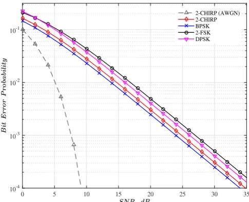
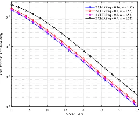
Fig. 3 shows the bit error probability for 2-ary chirp over AWGN channel, BPSK, 2-FSK, and DPSK versus the normalized SNR over Rayleigh fading channel. It is noted that the performance of binary chirp is very close to the performance of BPSK modulation over Rayleigh fading channel and better than the performance of 2-FSK and DPSK systems. In Fig. 4 and Fig. 5, the bit error probability performances of the 2-ary chirp system are illustrated as
a function of q and w, respectively. It is observed that as
the values of the modulation parameters deviate from the optimum values, the performance degrades.
SNR, dB
0 5 10 15 20 25 30 35
B
it
E
r
r
o
r
P
r
o
b
a
b
il
it
y
10-4 10-3 10-2 10-1
2-CHIRP (AWGN) 2-CHIRP BPSK 2-FSK DPSK
Fig. 3. Performance of 2-ary chirp system over Rayleigh fading channel
[image:3.595.303.546.491.688.2]SNR, dB
0 5 10 15 20 25 30 35
B
it
E
r
r
o
r
P
r
o
b
a
b
il
it
y
10-4 10-3 10-2 10-1
2-CHIRP (q = 0.36, w = 1.52) 2-CHIRP (q = 0.36, w = 1) 2-CHIRP (q = 0.36, w = 4) 2-CHIRP (q = 0.36, w = 7)
Fig. 4. Performance of 2-ary chirp system over Rayleigh fading channel as a function ofw=1.52, 1, 4, 7, for a fixed value ofq
SNR, dB
0 5 10 15 20 25 30 35
B
it
E
r
r
o
r
P
r
o
b
a
b
il
it
y
10-4 10-3 10-2 10-1
[image:4.595.47.293.51.251.2]2-CHIRP (q = 0.36, w = 1.52) 2-CHIRP (q = 0.1, w = 1.52) 2-CHIRP (q = 0.2, w = 1.52) 2-CHIRP (q = 0.9, w = 1.52)
Fig. 5. Performance of 2-ary chirp system over Rayleigh fading channel as a function ofq=0.36, 0.1, 0.2, 0.9, for a fixed value ofw
B. Nakagami-mFading Channel
The PDF of Nakagami-m model is given by [13]:
pγ(γ) =
m
γ
mγm−1
Γ(m)e
−mγ
γ, γ>0 (20)
m is the fading parameter which can be used to
gen-erate several fading channel model (m = 1
rep-resents Rayleigh model when there is no line of
sight (LOS) component). By expressing the
exponen-tial term in (20) as e−mγγ = G1,0
0,1
mγ γ
0
and
Q(p(1−ρ(i, j))γ) = √1
πG 2,0 1,2
(1−ρ(i, j))γ
1 0,1/2
in (12) using [(8.4.3/1),(8.4.14/2)][17] respectively, where
Gq,pa,b
x
... ...
is the Meijer G-function [16]. (16) yields to
the integral:
SNR, dB
0 5 10 15 20 25 30 35
S
y
m
b
o
l
E
r
r
o
r
P
r
o
b
a
b
il
it
y
10-4 10-3 10-2 10-1 100
[image:4.595.301.547.283.481.2]4-CHIRP (AWGN) 4-CHIRP 4-PSK 4-FSK
Fig. 6. Performance of 4-ary chirp system over Rayleigh fading channel
SNR, dB
5 10 15 20 25 30 35
S
y
m
b
o
l
E
r
r
o
r
P
r
o
b
a
b
il
it
y
10-4 10-3 10-2 10-1 100
8-CHIRP (AWGN) 8-CHIRP 8-PSK 8-FSK
Fig. 7. Performance of 8-ary chirp system over Rayleigh fading channel
Pav=
1 M√π
M
X
j=1
M
X
i=1
i6=j ∞
Z
0
γm−1G21,,02
(1−ρ(i, j))γ 1 0, 1/2
G10,,01
mγ γ
0
dγ (21)
By solving the integral in (21), a closed form expression
for the symbol error rate over Nakagami-m channel can be
written as:
Ps=
1
M√πΓ(m)
M
X
j=1
M
X
i=1
i6=j G22,,12
(1−ρ(i, j))
m
ΩEs
2N0
1,1−m
0,1/2
(22)
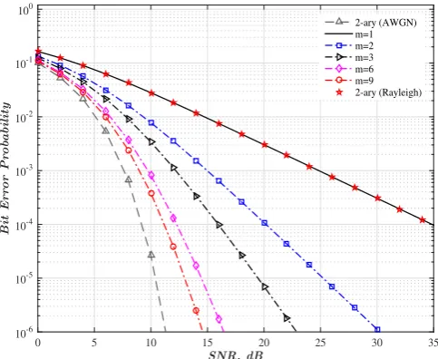
Figs. 8 to 10 show the performance of 2,4, and 8-ary
chirp modulation over Nakagami-mfading channel. For the
special case whenm= 1, Nakagami-mreduces to the well
known Rayleigh model. The performance approaches AWGN
performance asm→ ∞because the line of sight (LOS) path
dominates the received signal. Also, it is noted that as M
[image:4.595.48.291.304.502.2]modulation technique by changing the modulation order to increase the bandwidth efficiency or to improve the error rate performance to meet a certain quality of service [15] .
SNR, dB
0 5 10 15 20 25 30 35
B
it
E
r
r
o
r
P
r
o
b
a
b
il
it
y
10-6 10-5 10-4 10-3 10-2 10-1 100
[image:5.595.47.289.102.300.2]2-ary (AWGN) m=1 m=2 m=3 m=6 m=9 2-ary (Rayleigh)
Fig. 8. Performance of 2-ary chirp system over Nakagami-m fading
channel as a function ofm
SNR, dB
0 5 10 15 20 25 30 35
S
y
m
b
o
l
E
r
r
o
r
P
r
o
b
a
b
il
it
y
10-6 10-5 10-4 10-3 10-2 10-1 100
[image:5.595.47.290.352.549.2]4-ary (AWGN) m=1 m=2 m=3 m=6 m=9 4-ary (Rayleigh)
Fig. 9. Performance of 4-ary chirp system over Nakagami-m fading
channel as a function ofm
C. Generalized-K Fading and Shadowing Channel
The Generalized-K is a composite model that is used to
describe the fading and shadowing channel characteristics. This model represents a wireless channel that subjects to
short and long-term fading. The PDF of the Generalized-K
model is given by:
pγ(γ) = 2
cm
γ
c+2m γc+m2−2
Γ(c)Γ(m)Kc−m
2
rcm
γ γ
, γ>0
(23)
WhereKc−m(.)is the modified Bessel function of orderc−
m,Γ(.)is the Gamma function [16]. The coefficientscand
m are the shadowing and fading’s parameters; respectively.
As m and c increase, the fading and shadowing become
less sever. For m andc → ∞, the channel approaches that
SNR, dB
0 5 10 15 20 25 30 35
S
y
m
b
o
l
E
r
r
o
r
P
r
o
b
a
b
il
it
y
10-6 10-5 10-4 10-3 10-2 10-1 100
8-ary (AWGN) m=1 m=2 m=3 m=6 m=9 8-ary (Rayleigh)
Fig. 10. Performance of8-ary chirp system over Nakagami-m fading channel as a function ofm
of AWGN. using (12), (13), (16), (23) and expressing the modified Bessel function in (23) as
Kc−m
2qc m γ γ
= 1
2G 2,0 0,2
c m γ γ
(c−m)
2 ,
−(c−m) 2
!
and
Q(p(1−ρ(i, j))γ) = √1
πG 2,0 1,2
(1−ρ(i, j))γ
1 0,1/2
using [(8.4.23/1),(8.4.14/2)][17]. Thus, the integral of (31) can be expressed in terms of Miejer G-function as:
I= 1
2√π
∞
Z
0
γc+2m−1G2,0
1,2
(1−ρ(i, j))γ
1 0,1/2
G20,,02
c m γ γ
(c−m)
2 ,
−(c−m) 2
dγ (24)
average symbol error probability ((Pav)) of chirp
modu-lation overKG-channel is obtained in a closed form as:
Ps>
1 M√πΓ(c)Γ(m).
M
X
j=1
M
X
i=1
i6=j
G23,,22 (1−ρ(i, j)) m
ΩEs
2N0
1,1−c,1−m 0,1/2
!
(25)
Figs. 11 to 13 show the performance of 2,4 and 8-ary
chirp system overKG fading channel as a function ofcand
m. For comparison purposes, symbol error rate for Rayleigh
fading and AWGN channel are also plotted. Because of
the shadowing effect, the performance over KG channel
is poorer than the performance over AWGN and Rayleigh channel. Several techniques may be used to mitigate the effect of shadowing and fading on the performance. For
example, at a symbol error rate of 10−4 for 2-ary chirp
system, performance deteriorates by 5, 14, and 27 dB for
generalized-K with c = 6, m = 8, generalized-K with
[image:5.595.311.549.423.487.2]SNR, dB
0 5 10 15 20 25 30 35
B
it
E
r
ro
r
P
ro
ba
b
il
it
y
10-6
10-5 10-4 10-3 10-2 10-1 100
[image:6.595.48.289.52.230.2]c=1, m=2 c=1, m=4 c=3, m=2 c=3, m=4 c=3, m=8 c=6, m=2 c=6, m=4 c=6, m=8 2-ary (Rayleigh) 2-ary (AWGN)
Fig. 11. Performance of2-ary chirp system overKGfading channel as a function ofcandm
SNR, dB
0 5 10 15 20 25 30 35
S
y
m
bo
l
E
r
ro
r
P
ro
ba
b
il
it
y
10-6 10-5 10-4
10-3 10-2 10-1 100
[image:6.595.48.290.272.448.2]c=1, m=2 c=1, m=4 c=3, m=2 c=3, m=4 c=3, m=8 c=6, m=2 c=6, m=4 c=6, m=8 4-ary (Rayleigh) 4-ary (AWGN)
Fig. 12. Performance of4-ary chirp system overKGfading channel as a function ofcandm
SNR, dB
0 5 10 15 20 25 30 35
S
y
m
bo
l
E
r
ro
r
P
ro
ba
b
il
it
y
10-6 10-5
10-4 10-3
10-2 10-1 100
c=1, m=2 c=1, m=4 c=3, m=2 c=3, m=4 c=3, m=8 c=6, m=2 c=6, m=4 c=6, m=8 8-ary (Rayleigh) 8-ary (AWGN)
Fig. 13. Performance of8-ary chirp system overKGfading channel as a function ofcandm
IV. CONCLUSION
In this paper, closed-form SER expressions for M-ary
chirp systems over Rayleigh, Nakagami-mand
Generalized-K channels have been derived. The SER performances have
been plotted as a function of normalized SNR for different
modulation orders M and as a function of fading and
shadowing parameters. One of the major contributions of this paper is the derivation of closed-form expressions for the
performance over Rayleigh, Nakagami-m and
Generalized-K channel models forM-ary chirp communication system.
ACKNOWLEDGMENT
The first author would like to gratefully thank Taif Uni-versity and the ministry of higher education in Saudi Arabia for their support and scholarship.
REFERENCES
[1] Huemer, M.; Koppler, A.; Ruppel, C.C.W.; Reindl, L.; Springer, A.; Weigel, R., “SAW based chirp Fourier transform for OFDM systems,” Ultrasonics Symposium, 1999. Proceedings. 1999 IEEE , vol.1, no., pp.373,376 vol.1, 17-20 Oct. 1999.
[2] “The IEEE 802.15 Low Rate Alternative for
Wire-less Personal Area Networks (WPANs).” Available:
http://www.ieee802.org/15/pub/TG4a.html
[3] “Nanotron technologies for embedded location platform.” Available: http://nanotron.com/EN/
[4] Alsharef, Mohammad; Rao, Raveendra K.,“M-ary chirp modulation for coherent and non-coherent data transmission,” Electrical and Computer Engineering (CCECE), 2015 IEEE 28th Canadian Conference on , vol., no., pp.213,219, 3-6 May 2015.
[5] Gupta, C.; Mumtaz, T.; Zaman, M.; Papandreou-Suppappola, A., “Wide-band chirp modulation for FH-CDMA wireless systems: coherent and non-coherent receiver structures,” Communications, 2003. ICC ’03. IEEE International Conference on , vol.4, no., pp.2455,2459 vol.4, 11-15 May 2003.
[6] Khan, M.A.; Rao, R.K.; Xianbin Wang, “Closed-form error probability for M-ary chirp modulation in frequency-selective and -nonselective fading channels,” Electrical and Computer Engineering (CCECE), 2013 26th Annual IEEE Canadian Conference on , vol., no., pp.1,4, 5-8 May 2013.
[7] Khan, M.A.; Rao, R.K.; Xianbin Wang, “Performance analysis of MRC-chirp system over independent and correlated fading channels,” Electrical and Computer Engineering (CCECE), 2013 26th Annual IEEE Canadian Conference on , vol., no., pp.1,4, 5-8 May 2013. [8] Hengstler, S.; Kasilingam, D.P.; Costa, A.H., “A novel chirp modulation
spread spectrum technique for multiple access,” Spread Spectrum Tech-niques and Applications, 2002 IEEE Seventh International Symposium on , vol.1, no., pp.73,77 vol.1, 2002.
[9] Kadri, A.; Rao, R.K., “Binary Chirp Signals in - Mixture Noise: Co-herent and NoncoCo-herent Detection,” Signals, Systems and Electronics, 2007. ISSSE ’07. International Symposium on , vol., no., pp.579,582, July 30 2007-Aug. 2 2007.
[10] Moungnoul, P.; Tran Tuan Huang; Paungma, T., “Investigation of Multi-Linear Chirp FH-CDMA over Fading Channel Model,” Informa-tion, Communications and Signal Processing, 2005 Fifth International Conference on , vol., no., pp.1480,1484, 0-0 0.
[11] El-Khamy, S.E.; Shaaban, S.E.; Thabet, E.A., “Frequency-hopped multi-user chirp modulation (FH/M-CM) for multipath fading chan-nels,” Radio Science Conference, 1999. NRSC ’99. Proceedings of the Sixteenth National , vol., no., pp.C6/1,C6/8, 23-25 Feb 1999. [12] M. A. Alsharef, “ M-ary chirp modulation for data transmission,”
M.E.Sc. thesis, The Univ. of Western Ontario, 2011.
[13] M. K. Simon and M. S. Alouini, Digital Communication over Fading Channels, 2nd ed. New York: Wiley, 2005.
[14] Hamed, Abdulbaset M.; Alsharef, Mohammad; Rao, Raveendra K., “Bit error probability performance bounds of CPFSK over fading channels,” Electrical and Computer Engineering (CCECE), 2015 IEEE 28th Canadian Conference on , vol., no., pp.1329,1334, 3-6 May 2015. [15] Hamed, A.M.; Rao, R.K.; Primak, S.L., “ Adaptive multidimensional modulation over faded shadowing channels,” Electrical and Computer Engineering (CCECE), 2014 IEEE 27th Canadian Conference on , vol., no., pp.1,4, 4-7 May 2014.
[16] “The Wolfram functions site for special mathematical functions.” Wolfram Research, Inc 2015. Available: http://functions.wolfram.com [17] A. P. Prudnikov, Yu. A. Brychkov, and O. I. Marichev, Integrals and
[image:6.595.47.288.490.668.2]