Abstract— Inorganic membranes have been used to determine the separation of C3H8, N2, O2 and CO2 from CH4. Composite
alumina/zeolite was evaluated. Physical properties of the modified membrane were investigated by nitrogen physisorption measurements. Results indicate that the permselectivity of the membrane depends on the material that was used for surface modification. Single gas permeation tests were carried out at a pressure range of 0.01 to 0.1 MPa. The Fickian approach assumes that the transport diffusivity of gases through the zeolite membrane is dependent on the operating temperature and hence the flux of carbon dioxide, nitrogen, methane, propane and oxygen was determined at 372, 473 and 573 K and the activation energy of the gases was determined. On the basis of the results obtained it can be concluded that temperature did affect the flux of gases in the zeolite membrane and the Fickian model can be used to determine transport through the zeolite layer.
Keywords— Fickian model, Flux, Gas separation, Membrane and Zeolite
I. INTRODUCTION
HE production of crude oil from wells that access sub-sea reservoirs is facilitated by large systems of offshore production units that are located close to one or more sub-sea wells in an oil field. At these production units, the removal of contaminants from the crude oil is carried out to facilitate the transportation of the crude from the offshore production unit to onshore storage facilities or refineries via pipelines. However, new wells are being drilled at remote locations, where the sea bottom has uneven terrain; hence the use of pipelines becomes complex and relatively more expensive. There is therefore the need for a cost effective and environmentally safe system for the effective transportation of crude oil from these remote offshore facilities to onshore refineries (1). Although the transport system does not appear complicated, each segment has its challenges. The major complexity for crude oil transportation is the location of the oil well. With increasing
Manuscript received 20 August 2016.
H. Shehu is a PhD researcher at the Robert Gordon University, working at the Center for Process Integration and Membrane Technology (e-mail: [email protected]).
E.Okon is a PhD researcher at the Centre for Process Integration and Membrane Robert Gordon University Garthdee Road, Aberdeen ([email protected]).
Prof E.Gobina is the Director of Centre for Process Integration and Membrane Technology Ideas Research Institute Robert Gordon University Garthdee Road, Aberdeen ([email protected])
distance there is no real competitive choice to the shuttle tanker (2).
The global increase in remote oil field discoveries has increased the need for the use of shuttle tankers as a means for transporting crude oil as well. The presence of crude oil vapour in the tanker has motivated research into the use of membrane technology as a viable option for the recovery of hydrocarbons from crude oil during shuttle tanker loading and offloading operations. In the last few years, the potentialities of membrane operations have been widely recognized. In some preliminary investigations, polymeric membranes such as silicone rubber have been used. The membranes that are more permeable to lighter hydrocarbons are the polyacetylene polymers, the microporous absorbent carbon and the silicon rubber (3). Though they have high selectivity, they cannot withstand harsh chemical environments as well as high temperatures. Ceramic membranes on the other hand have adequate thermal and chemical durability (4). The use of ceramic membranes has grown considerably both academically as well as industrially and they can be used for several applications. They are generally more fragile and expensive to fabricate than polymeric membranes but they can withstand more severe separation conditions such as include temperatures or
corrosive solvents (5). Ceramic membranes do not only have higher thermal and
chemical stability but have higher permeability as well (4). There are several types of support used for these membranes and includes materials such as zeolites, silica, alumina and stainless steel (6).
Intra crystalline permeation through a zeolite membrane can be described using various approaches (7, 8, 9). The Fickian approach uses the concentration gradient as the driving force in a zeolite membrane while in the Maxwell-Stefan (MS) approach the driving force is the gradient of the thermodynamic potential. The MS approach allows for the approximation of the flux through the membrane for multicomponent gas mixtures by using the information from single gas permeations (10). For the permeation of single gas components through a zeolite membrane in a wide range of temperatures, the Fickian approach can be applied and the assumption that the total flux, N is the combination of the surface flux, Ns which takes place at low to medium temperatures and the activated gaseous flux, Ng which is prevalent at high temperatures (11), as shown in equation (1).
𝑁 = 𝑁𝑠+ 𝑁𝑔 [1] The surface flux can be expressed as:
A Fickian Model for Gas Transport through a
Zeolite Membrane
H. Shehu, E. Okon, E. Gobina, Member, IAENG
𝑁𝑠= 𝐷𝑠 𝑑𝑐
𝑑𝑧 [2] Where dc/dz is the concentration gradient and Ds is Fick’s diffusivity and is given by:
𝐷𝑠= 𝐷𝑜Г [3] Where Do is the intrinsic or corrected diffusivity and Г is the thermodynamic correction factor and is expressed as:
Г = 𝑑𝑙𝑛 𝑝𝑖
𝑑𝑙𝑛 𝑐𝑖 [4]
Where Pi and ci are the pressure and concentration of the component i respectively.
The transport diffusivity is dependent on the temperature and this is more apparent at higher temperature. The assumption of an Arrhenius type dependence on temperature is assumed (10) and is given by equation [5].
𝐷𝑜= 𝐷͚𝑒−𝐸𝐷𝑖𝑓𝑓 𝑅𝑇 [5]
Where Do is the intrinsic or corrected diffusivity.
The dependence on the temperature will be affected by the adsorption of the component on the zeolite as well as the operating pressure. At elevated temperatures, the adsorption phenomena can be negligible and thus the molecules can be considered to be in a quasi-gaseous state in the zeolite framework. This is referred to as activated Knudsen diffusion or gas translational diffusion. When this occurs the flux is expressed as:
𝑁𝑔 = − 𝐷𝑔𝑑𝑝
𝑅𝑇𝑑𝑧 [6] Where dp is the pressure gradient and dp/dz the permeance driving force. The diffusion coefficient that is dependent on the gas molecular velocity is given by:
𝐷𝑔 = 𝑑𝑝𝑢𝑚𝑒−𝐸𝑒 𝑅𝑇 [7]
Where dp is the pore diameter and um is the average velocity.
For ideal gases, the kinetic theory can be used to calculate the molecular velocity is given by equation 8:
𝑢𝑚 = 8𝑅𝑇
𝜋𝑀 [8] From the equations above, it can be seen that gas transport through a zeolite membrane is dependent on the adsorptive interaction between the permeating gas molecule and the zeolite. The permeating flux is supposed to increase with increase in temperature. This is true for a defect free zeolite membrane. In the presence of defects in the zeolite layer, Knudsen and viscous flow can contribute to the overall flux (10).
II. EXPERIMENTAL
A. Zeolite membrane preparation
The zeolite membrane was prepared by the dip-coating method. A solution containing silicone oxide, aluminium oxide, sodium oxide and deionised water was prepared and homogenised at room temperature for 20 hours. Zeolite crystals were deposited on alumina support which is subsequently dipped into the solution and kept for 20 hours at 343 K. The membrane was washed with deionised water and the pH of the rinse water was monitored. When the rinse water pH was neutral the membrane was air dried for 20 minutes and thermally treated in the oven at 338 K for 2 hours prior to permeation test.
B. Characterization
Nitrogen physisorption measurements were carried out at 77.35 K using a quantachrome adsorption gas analyser to determine the pore size and surface area of the membrane using the Barret Jones-Halenda and BET methods respectively.
III. RESULTS AND DISCUSSION
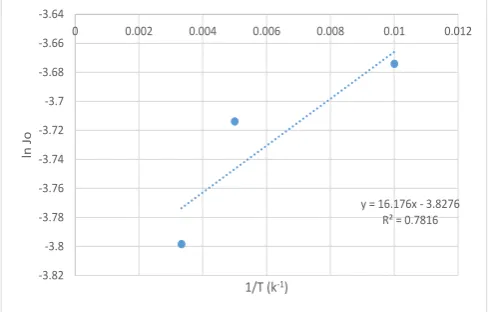
The transport of gases through the zeolite membrane is dependent on temperature as explained in equation 11. The flux of carbon dioxide, nitrogen, methane, propane and oxygen was determined at 372, 473 and 573 K. The gas flux J through the membrane can be written as an Arrhenius dependency equation (equation 15).
𝐽𝑜= 𝐽͚𝑒𝑥𝑝−𝛥𝐸 𝑅𝑇 [9]
This equation can be re-written as: 𝑙𝑛𝐽𝑜= 𝑙𝑛𝐽͚− 𝛥𝐸
𝑅𝑇 [10] Where 𝐽𝑜 is the flux (mols-1m-2), 𝐽͚ is the Arrhenius-type pre-exponential constant (m2s-1), T is the temperature (K), R is the molar gas constant (8.3144621 Jmol-1K-1), 𝛥𝐸 can be expressed as the activation energy of surface diffusion or heat of adsorption.
Using the straight line equation:
𝑦 = 𝐾 − 𝑚𝑥 [11] With y for ln Jo, K for ln J∞ m for ∆E/RT and x for 1/T
A plot of 𝑙𝑛𝐽𝑜 against 1
[image:2.595.306.551.609.765.2]𝑇 can be used to determine the activation energy ∆E. A positive slope indicates the heat of adsorption; however, a negative slope indicates activation energy of surface diffusion.
Fig. 1: Effect of temperature on the flux of CO2 transport
y = 16.176x - 3.8276 R² = 0.7816
-3.82 -3.8 -3.78 -3.76 -3.74 -3.72 -3.7 -3.68 -3.66 -3.64
0 0.002 0.004 0.006 0.008 0.01 0.012
ln
Jo
Fig. 2: Effect of temperature on the flux of CH4 transport
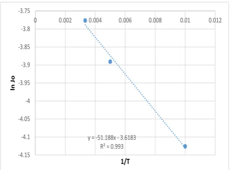
Fig. 3: Effect of temperature on the flux of O2 transport
[image:3.595.308.555.326.437.2]Fig. 4: Effect of temperature on the flux of C3H8 transport
Fig. 5: Effect of temperature on the flux of N2 transport
From the graphs Fig 1-5 the activation energies of the gases was calculated using equation (10) and presented in Table 1.
Table I: Activation energies calculated from flux and temperature dependence
gas Activation energy (Jmol-1)
CO2 134.449
Methane 226.7104
Oxygen -425.592
Propane 239.1156
Nitrogen -260.742
[image:3.595.57.299.493.651.2]The value of the activation energy of a gas is an indicator of the barrier for the transport of that gas through a membrane. Lower value of activation energy of oxygen and nitrogen represents a lower resistance for these gases to pass through the zeolite and support layer. The result indicates that the adsorbing gases on the surface of the zeolite layer are carbon dioxide, methane and propane. This is the expected transport mechanism of gases through a zeolite layer.
Fig. 6: Permeation test of y-type zeolite membrane at 293k
y = 27.267x - 3.4538 R² = 0.9885
-3.4 -3.35 -3.3 -3.25 -3.2 -3.15
0 0.002 0.004 0.006 0.008 0.01 0.012
ln
Jo
1/T (K-1)
y = -51.188x - 3.6183 R² = 0.993 -4.15
-4.1 -4.05 -4 -3.95 -3.9 -3.85 -3.8 -3.75
0 0.002 0.004 0.006 0.008 0.01 0.012
ln
Jo
1/T
y = 28.759x - 3.5394 R² = 0.9804
-3.5 -3.45 -3.4 -3.35 -3.3 -3.25 -3.2
0 0.002 0.004 0.006 0.008 0.01 0.012
ln
Jo
1/T
y = 28.759x - 3.5394 R² = 0.9804
-3.5 -3.45 -3.4 -3.35 -3.3 -3.25 -3.2
0 0.002 0.004 0.006 0.008 0.01 0.012
ln
Jo
[image:3.595.312.543.580.756.2]Fig. 6 shows the permeance of the various permeance through the zeolite membrane. The permeance were in the range of 10-6 molm-2s-1Pa-1 for CO2, CH4, He and N2, but in the range of 10-7 for propane. These permeances are relatively high when compared to literature values (12). The maximum selectivity for this membrane was calculated and presented in Table 3:
Table III: Maximum selectivity of methane through a zeolite membrane at 293 K
Gas mixture
CH4/CO2 CH4/C3H8 CH4/N2 CH4/He
Selectivity 2.9 3.3 1.4 1.2
The selectivity of methane over the propane, carbon dioxide and the inert gases shown in Table 3 is quite high with the zeolite membrane. The selectivity of methane over propane (3.3) is higher than the values ranging from 1.42 to 2.56 obtained from the work of Tirouni, Sadeghi and Pakizeh (13).
The adsorption isotherm of the zeolite membrane (Fig. 6) indicates that the zeolite may be non-porous adsorbent with weak adsorbent-adsorbate interaction (14). In theory, zeolites and silica are highly porous and have very large surface area.
Figure 6: Physisorption isotherm for zeolite membrane
The adsorption behaviour of mesoporous materials is determined by both adsorbent-adsorbate interactions. Hence the Kelvin equation (equation 4) which is based on cylindrical pores is used for the evaluation of the pore size distribution of the membrane layer by the Barrett-Joyner-Halenda (BJH) method. The BJH graph (Fig. 7) shows the adsorption and desorption branches which are used to determine the pore sizes of the membrane.
𝑟
𝑝= 𝑟
𝑘+ 𝑡
(12)Where rp is the pore radius of the membrane layer, rk is
the kelvin radius and t is the thickness of the membrane layer. Table 4 shows the pore size of the zeolite membrane that was determined using equation 12.
Figure 7: BJH desorption branch for pore size
determination for zeolite membrane
Table IV: Pore size and surface area of zeolite
membrane
Zeolite membrane
Pore size (x10-9 m) 11.394 Specific surface area (m2/g) 0.619
IV. CONCLUSION
In this work the impact of pressure drop and pore size on the separation performance of zeolite membranes for the separation of carbon dioxide, propane, nitrogen and helium from methane has been demonstrated. Zeolite membrane was studied and characterized. It was found that the activation energy of the hydrocarbon gases were much higher than those for nitrogen and oxygen. This study has confirmed shown that zeolite membrane could be used for the removal of carbon dioxide from natural gas. Further studies are planned to demonstrate membrane performance for separating could be used to separate the heavier components of natural gas mixtures that arise during dew point adjustments, thermal problems during transportation as well as when expanding highly compressed natural gas components.
REFERENCES
[1] Egge TG, Helgoy KE, Hildén TE, Oma N. Crude oil transportation system. 2005
[2] Inkpen A, Moffett MH. Global Oil and Gas Industry - Management, Strategy and Finance. PennWell; TY: GEN. [3] Baker RW, Lokhandwala K. Natural gas processing with
membranes: an overview. Industrial & Engineering Chemistry Research. 2008; 47(7):2109-2121.
[image:4.595.316.563.46.283.2] [image:4.595.48.294.376.567.2][5] Schüth F, Sing KSW, Weitkamp J. Handbook of porous solids. : Wiley-Vch; 2002.
[6] Li H, Schygulla U, Hoffmann J, Niehoff P, Haas-Santo K, Dittmeyer R. Experimental and modeling study of gas transport through composite ceramic membranes. Chemical Engineering Science. 2013; .
[7] Burggraaf A. Single gas permeation of thin zeolite (MFI) membranes: theory and analysis of experimental observations. Journal of Membrane Science. 1999; 155(1):45-65.
[8] Den Exter M, Jansen J, van de Graaf J, Kapteijn F, Moulijn J, Van Bekkum H. Zeolite-based membranes preparation, performance and prospects. Studies in Surface Science and Catalysis. 1996; 102:413-454
[9] Krishna R, Van Baten J. Describing binary mixture diffusion in carbon nanotubes with the Maxwell-Stefan equations. An investigation using molecular dynamics simulations. Industrial & Engineering Chemistry Research. 2006; 45(6):2084-2093.
[10]Basile A. Handbook of Membrane Reactors: Fundamental Materials Science, Design and Optimisation. : Elsevier; 2013 [11]Xiao J, Wei J. Diffusion mechanism of hydrocarbons in
zeolites—I. Theory. Chemical Engineering Science. 1992; 47(5):1123-1141.
[12]Kusakabe K, Kuroda T, Murata A, Morooka S. Formation of a Y-type zeolite membrane on a porous α-alumina tube for gas separation. Industrial & Engineering Chemistry Research. 1997; 36(3):649-655.
[13]Tirouni I, Sadeghi M, Pakizeh M. Separation of C 3 H 8 and C 2 H 6 from CH 4 in polyurethane–zeolite 4Å and ZSM-5 mixed matrix membranes. Separation and Purification Technology. 2015; 141:394-402.