Abstract— Friction stir welding is a newly developed solid state welding process, which was developed by The Welding Institute in the year 1991. The development of FSW has allowed the process to be used in different applications for different industries, which include aerospace and automobile industry. Due to the increase in the demand of high strength and low weight components in different manufacturing applications, there is a need for using pure aluminium and its alloys in lap configuration. Research studies are required to characterize and obtain optimum process parameters, which can be used to produce good quality lap welds. This paper reports lap welded 1050 Aluminium Alloy using friction stir welding process and established the effect of rotational speed on the joint integrity of the welds. The welds were produced by varying the rotational speed in the range of 1200 and 2000 rpm, and maintaining the traverse speed constant at 150 mm/min. The welds were characterized through microstructural evaluation, microhardness profiling and tensile testing in order to determine the joint integrity of the welds. The results from the macrograph of the welded joints, show a basin shaped nugget resulting from the stirring of the tool during the welding process. Fine and equiaxed grains characterized the microstructure in the stirred zone, which was a result of a dynamic recrystallization. The tensile test data revealed that as the tool rotational speed was increased, the fracture strength also increases, the highest value of the fracture strength was 195 N/mm and was found on the welds produced at 2000 rpm. High Vickers microhardness values were measured at the nugget zone with the highest value found to be 31.88 HV. It was revealed that the welds produced at the rotational speed of 2000 rpm exhibited the optimum welding parameters to join 1050 Aluminium Alloy.
Keywords — Friction Stir Lap Weld, Joint Integrity and
Rotational Speed
I. INTRODUCTION
any industries are adapting to the use of aluminium and its alloys to manufacture products instead of using steel. The wide use of aluminium is due to its low density as compared to steel, also it strength, which can be increased by adding alloy elements such as copper, magnesium, steel, lead, titanium etc. When manufacturing big systems such as aircrafts or ships, parts made from aluminium and its alloys must be joined to form certain components being built. The most common joining technique that is used to build these structures is welding.
Stephen A. Akinlabi is with the Department of Mechanical Engineering Science, University of Johannesburg, South Africa. (Corresponding author phone: +27783160281; e-mail: [email protected])
Esther T. Akinlabi is an Associate Professor and the Head of Department, Department of Mechanical Engineering Science, University of
Aluminium has been identified as the most common metal on earth. Only silicon and oxygen exists in more quantities than aluminium. Aluminium assumes a crystalline structure when it changes from the molten to solid state. The atoms are arranged in a definite ordered symmetrical pattern, which is known as a lattice structure [1]. Aluminium and its alloys are widely used in aerospace but it is a challenge to produce high-strength, fatigue and fracture resistant welds made from aluminium alloys such as 2XXX and 7XXX series which are classified as non-weldable [2]. These alloys are classified as non-weldable because of the weak solidification microstructure and permeability in the fusion zone when using fusion-welding technique. The loss in the mechanical properties is very critical when joining aluminium or its alloys through welding; hence it is significant to understand the fundamental welding techniques when welding these materials.
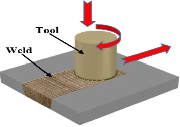
[image:1.595.340.518.457.583.2]Friction stir welding (FSW) is a solid state welding technique developed by TWI in 1991 [3]. A typical FSW process is shown in Fig. 1. Since its invention, FSW has advanced as a process of preference in joining aluminium components. FSW allows many alloys, which are regarded, non-weldable by fusion technique possible to weld.
Fig. 1: Schematic of a Friction Stir Welding Process
The tool is the fundamental component of Friction Stir Welding (FSW) and has evolved empirically based on observations of forces; weld defects, rotational speeds, transverse speeds and the resulting material flow [4]. Tool attributes that could alter the characteristics of a FSW joint are the shoulder diameter and the pin size (length, thickness and shape). Since its invention, the process has been continually improved and its scope of application greatly expanded. The relative motion between the tool and the substrate generates frictional heat that creates a plasticized region around the immersed portion of the tool and the tool shoulder prevents the plasticized material from being expelled from the weld, forcing the plasticized material to coalesce behind the tool to form a solid–phase joint [5]. Components are joined by plunging a rotating tool with a pin attached to its end through the
Effect of Rotational Speed on Joint Integrity of
Friction Stir Lap Welded Aluminium
Esther T. Akinlabi, Member, IAENG and Stephen A. Akinlabi, Member, IAENG
welding line of the workpiece thereby generating frictional heat, which forms a plasticized region around the pin and the interface between the shoulder of the tool and the workpiece [6]. If the process parameters are appropriately chosen, good welds can be produced by FSW. Good welds are achieved by varying the welding parameters, which affect the evolving microstructure and the properties of FSW joints. In this paper, the rotational speed which plays a significant role in the outcome of the weld during the friction stir lap welding of aluminium was varied in order to obtain optimum settings. The welds were analyzed and the results are presented.
II. LITERATURE REVIEW
Joining of materials is a fundamental step when manufacturing integrated systems. There are different types of joining techniques, which includes mechanical fastening, adhesive bonding and welding. The type of joining technique selected depends on the size of structures and design considerations. Prior to the development of advanced joining techniques, large aircraft components were joined using mechanical fastening, while shipbuilding used different types of welding techniques [7], [8].
The manufacturing of smaller systems such as automobiles uses a variety of techniques, which includes welding and adhesive bonding. The joining technique has an impact on the function of the work piece and as a result, it is an important consideration. Improper joining procedure can lead to disastrous failures [8].
Joining techniques of metals can be divided into four basic groups: adhesive bonding; fusion welding; brazing and soldering and solid state joining [8]. Fusion welding technique involves melting a portion of the base metals to form a solid weld. In brazing and soldering, the filler metal melts in between the base metals to form an alloy with the base metal resulting in a bond formation upon solidification. Adhesive bonding joins metals using glue as a filler material, while solid state joining process depends on deformation and/or atom diffusion to form the join without melting the base metal or filler metal.
Welding is the process of joining two or more pieces of material to form a single piece and is formed by heating the material to a temperature high enough to cause the material to soften or melt and mix [7]. In other cases, pressure may be required to force the separate pieces of material to join and form a single piece. Filler material is added in the welding process when there is a need to form a completed weld in the joint. There are many different types of welding techniques, which range from the conventional arc welding to energy beam welding. Generally, welding is categorized according to two groups; fusion and solid-state welding.
Fusion welding technique involves melting a portion of the base metal and filler metals to join two or more work pieces without applying an external pressure. The process is a high temperature process, which involves chemical interaction between the molten and solid metals as well as metal-melt gas or slag [9]. The liquid metal produced during fusion welding is mainly for dissolving certain portions of gases from atmospheric air and gaseous products of the electrode coating or flux. The gases are dissolved in order not to interfere with the metal properties. The different types of fusion welding includes but not limited to: electric arc
welding, laser welding and gas welding. During fusion welding, there could be a need for preparing the surface such as removing the oxide layer before welding can proceed.
Solid state welding processes is a non-melting process where coalescence is produced at temperatures below the melting point of the base metals with or without introducing a filler metal. The process relies on pressure and deformation and can be divided into two categories; diffusion bonding and deformation bonding. In diffusion bonding, no gross deformation of the surface occurs. The process occurs at an elevated temperature below the melting temperature of the metal where atomic diffusion occurs across the interface to fill in any voids and complete the joining process. Similar or dissimilar metals are allowed to bond through atomic bonding [10].
In deformation bonding processes, applied pressures above the yield strength of the work are imposed on the work piece to cause gross deformation, and forcing atoms of the surfaces to be joined to interact with each other. The pressure to the work is provided through numerous methods such as cold welding, forge welding, hot pressure welding, roll welding, ultrasonic welding, explosive welding, friction welding, resistance welding and friction stir welding [8]. Friction stir welding offers a unique approach in terms of the way material flows and mix to form a solid phase joint. One of the benefits of solid state welding is that there is less formation of defects and the base metals have the ability to retain their original properties while keeping the Heat Affected Zone (HAZ) small as compared to fusion welding processes [11].
FSW is a relatively simple process that produces a weld between two or more work pieces by thermal and material flow. The success of FSW has enabled the possibility to weld similar and dissimilar materials [12]. The use of FSW is rapidly replacing the conventional mechanical fastening as far as joining is concerned. Aluminium and its alloys are important for manufacturing components and structures because of their good mechanical properties, which include low density and high strength. During the process of FSW, a non-consumable rotating cylindrical tool with a pin is inserted into the abutting edges of the work piece to be joined and travels along the joint line to form a weld. The result of various geometrical features on the tool, material movement around the pin can be complex, with gradients in strain, temperature and strain rate. The resulting nugget zone microstructure resulted after FSW; reflect these different thermomechanical histories that are inhomogeneous. Regardless of the central microstructural inhomogeneity of the weld interface, one of the crucial benefits of this technique is the formation of fully recrystallized, equiaxed, fine grain microstructure formed in the nugget by the severe plastic deformation at raised temperature. The fine grain microstructure produces excellent mechanical properties, fatigue properties, enhanced formability and excellent super-plasticity [13].
distribution, all of which have an influence on the microstructural evolution of material.
The influences of tool geometry and various rotational speeds on macrostructure, microstructure and joint strength of FSW of AA5456 aluminium alloy in lap joint configuration with two different tempers was investigated by Salari et al. [14]. Four types of tool pin profiles were employed: a conical thread pin, a cylindrical-conical thread, a stepped conical thread and a flared triflute pin. Two rotational speeds of 600 and 800 rpm were used. The results showed that tool geometry influences significantly the material flow in the stir zone and it accordingly control the weld mechanical properties.
The two important FSW parameters are: tool rotational speed moving in clockwise or anticlockwise direction and the tool traverse speed along the joint line [2]. The rotation of the tool results in the stirring and mixing of material around the rotating pin while the translation of the tool transports the stirred material from the front to the back of the pin and finishes the welding process [2], [13], [15]. Greater tool rotation rate produces higher temperature because of the increased frictional heating and this result in more intense stirring and mixing of the material [16]. The choice of feed rate and rotational speed are significant for heat generation in producing good material flow around the tool while minimizing the forces on the tool during the welding procedure.
A study on the effect of welding parameters on the microstructure and mechanical properties was also investigated by Zhang et al. [17]. The results obtained showed that the nugget zones of all joints had fine equiaxed grains and grain size of the nugget zones decreased with increasing welding speed or the decreasing tool rotation rate. It was also observed that the lowest hardness appeared in the transition zone between the advancing sides of the TMAZ and HAZ.
The investigation on the effect of process parameters on FSW of aluminium alloy 2219-T87 was conducted by Arora et al. [18]. Metallographic studies showed fine equiaxed grains in the nugget zone and microstructural changes in TMAZ were found to be the results of joint and interactive influences of frictional heat and deformation. Further results revealed that the downward or the forging force was dependent upon the shoulder diameter and the rotational speed while the welding force was dependent on welding speed and pin diameter. Furthermore, Singh et al. [19] studied the effect of tool rotational speed and welding speed on mechanical and metallurgical properties of friction stir welded joints of aluminium alloy AA 6082-T651. They found that no defects were observed in the weld joints obtained at tool rotation speed of 300-700 rpm and welding speed of 15-35 mm/min respectively.
III. METHODOLOGY
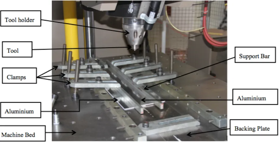
The material used in this study is 3 mm commercial 1050 Al alloy sheet, with a dimension of 600 x 100 x 3 mm3. A weld length of 100 mm was produced for each weld using a lap weld configuration. The experimental setup is shown in Fig. 2. The welds were produced using Intelligent Stir Welding for Industry and Research Process Development System (I-STIR PDS), at the Friction Processing Research Institute, Nelson Mandela Metropolitan University, Port Elizabeth.
The welds were produced with rotational speed ranging from 1200 to 2000 rpm in step of 200. The traverse speed was kept constant at 150 mm/min. The welds were produced at position control mode.
[image:3.595.69.529.509.745.2]The welded samples of size 25 × 5 × 6 mm3 were sectioned at the joint interface and mounted in polyfast thermoplastic hot mounting resin, the samples were grinded and polished. All the polished samples were etched with Keller’s and Weck’s reagent. The etched samples were
consequently viewed under the Olympus optical microscope to observe the microstructure. Tensile test was conducted using 100 kN servo-hydraulic Instron Universal tensile testing machine in order to evaluate the mechanical strength of the FSW lap joints. Three samples were tested for each of the rotational speed employed. The samples were pulled at an extension rate of 1 mm/min. Vickers microhardness measurement was conducted along the transverse weld centreline at intervals of 2 mm using a digital microhardness tester. A load of 100g and a dwell time of 10 seconds were used for the measurement.
I. RESULTS AND DISCUSSION
The experimental results from the characterization of all the welded samples are presented in this section.
A. Welded Joint Top Appearances
The top surface appearances of the welded sheets is presented in Figure 3.
Fig. 3: Top surface showing the weld flash
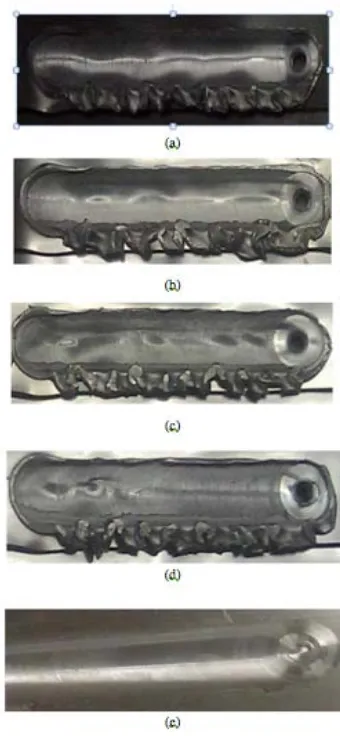
The welded joints were visually inspected to investigate the surface appearances of the welds. The effect of tool rotational speeds on surface appearances of the welded joints is shown in Fig. 4(a)-(b).
The tool traversed at a constant welding speed of 150 mm/min and a tool depth of 5.8 mm was employed. The tool pin was plunged into the workpiece through the centerline of the welding direction. It pressed the bottom plate downward, filled up the gap between the two plates as a result, forming a welded joint.
B. Microscopic Analysis
The micrograph of the welded joint is shown in Fig. 5. A basin shaped nugget that widens near the upper surface in the welded region was observed. The basin shaped nugget zone is due to the intense deformation and frictional heating between the upper surface and the tool shoulder during FSW [2].
The microstructure of the base metal is shown in Fig. 6. The microstructure of the stirred zone is shown in Fig. 7 with the grains fine and equiaxed. These are smaller grain sizes compared to the base metal of elongated grain structure. The transformed grain structure in the stirred zone is the result of the dynamic recrystallization due to the frictional heat generated by the pin and the shoulder contact on the material being welded and plastic deformation of stirring.
Fig.4 (a)-(b): Top appearance of welded joint at content transverse speed of 150 mm/min with tool rotational speed of (a) 1200 rpm, (b) 1400 rpm, (c)
[image:4.595.341.511.54.422.2]1600 rpm, (d) 1800 rpm, (e) 2000 rpm
[image:4.595.55.278.305.380.2]Fig. 5: Macrostructure of the welded joint
[image:4.595.314.543.477.538.2]Fig. 7: Micrograph of the stirred zone
C. Microhardness Measurements
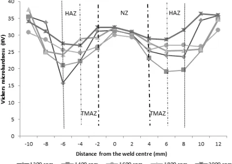
The Vickers microhardness was measured at cross section along the welding line in order to investigate the variation of hardness with difference of the welding. The microhardness profiles of the welds are shown in Fig. 8 and can be seen that, higher Vickers microhardness values were measured in the nugget zone, which is a region, previously occupied by the tool pin and Thermomechanically Affected Zones (TMAZ) for all the friction stir welded joints when not taking into account the base material. The range was between 30 HV and 32 HV.
Fig. 8: Microhardness profiles of welds produced at 1200, 1400, 1600, 1800 and 2000 rpm respectively at constants transverse
speed of 150 mm/min
These regions (TMAZ and HAZ) were previously occupied by the tool pin and the shoulder during the welding process. The increase in hardness at these regions can be attributed to plastic deformation that occurred in the regions during the welding process. The microhardness values were low in the Heat Affected Zone (HAZ) regions. The microhardness values in this region range between 16 HV and 20 HV.
The average microhardness of the weld stir zone increased to a maximum from 31 to 32 HV when the tool rotational speed increased from 1800 to 2000 rpm respectively. The average microhardness values corresponding to 1200 rpm, 1400 rpm and 1600 rpm where 31 HV, 29 HV and 29 HV respectively. It is well reported in literature that, at a constant traverse speed, as the rotation speed increase the rate of heat input also increases [20]. High heat input resulted in stirring and mixing of the material to a great extent.
II. CONCLUSION
The lap welds of 1050 Aluminium Alloy sheets were successfully produced through friction stir welding process by varying the rotational speed to obtain the optimum parameters. The welded samples were characterized and analyzed through the top surface examination of the joints, microstructural evaluation, and microhardness measurements. From the visual top appearance of the welds, it was observed that most of the welded joints had formation of weld flash on one side of the welded region with the exception of the weld produced at 2000 rpm. Semi-circular tracks on the surface of the welded region were visible at all rotational speeds and the surface morphology on the welded region became smoother as the tool rotational speed was increased.
The macrostructure of the welded joint exhibited a basin shaped in the nugget, which resulted from intense deformation and frictional heating in the upper surface. The microstructure in the stirred zone was characterized by fine and equiaxed grains and smaller grain size compared to the base metal. The transformed stirred zone was due to the dynamic recrystallization and plastic deformation. The microhardness profile results revealed that high Vickers microhardness values were measured in the nugget zone, which was the region previously occupied by the pin and at the TMAZ. The maximum value 32 HV was obtained for welds produced at rotation speed of 2000 rpm. The high value of the hardness was attributed to the plastic deformation that occurred in the welded regions.
ACKNOWLEDGMENT
The authors thank the staff members of the National Laser Centre that assisted with the operation of the laser facility and support during the period of the experiment. Esther Akinlabi acknowledges the Johannesburg Institute of Advanced Study for the writing fellowship award (February to May 2016).
REFERENCES
[1] R. Cobden. "Aluminium: Physical Properties, Characteristics and Alloys," Training in Aluminium Applications Technologies, 1994.
[2] R. S. Mishra and Z. Y. Ma, “Friction stir welding and processing,” Materials Science and Engineering R, vol. 50, pp. 1-78, 2005.
[3] W. M. Thomas, K. I. Johnson and C. S. Wiesner, “Friction Stir Welding-Recent developments in tool and process technologies,” Advanced engineering materials, vol. 5, pp. 485-490, 2003.
[4] E. T. Akinlabi (2011). Characterization of dissimilar friction stir welds between aluminium and copper. Lambert Academic Publishing. Germany. ISBN 978-3-8443-9042-1. p. 12-17
[5] E. T. Akinlabi and S. A. Akinlabi. Friction Stir Welding Process: A Green Technology. World Academy of Science, Engineering and Technology 71 2012.
[6] R. Nandan, T. DebRoy and H. K. Bhadeshia, “Recent advances in friction-stir welding – Process, weldment structure and properties,” Progress in Materials Science, vol. 53, pp. 980-1023, May 2008
[image:5.595.48.287.349.518.2][8] R. S. Mishra, P. S. De and N. Kumar, “Introduction,” in Friction Stir Welding and Processing, Springer, 2014, pp. 1-11.
[9] G. Deyev and D. Deyev, Surface Phenomena in Fusion Welding Processes, G. F. Deyev, Ed., CRC Press, 2005. [10] M. P. Groover, Fundamentals of Modern Manufacturing:
Materials, Processes and Systems, fourth ed., John Wiley & Sons, 2010.
[11] E. T. Akinlabi and S. A. Akinlabi, “Condition Monitoring During Friction Stir Welding of Dissimilar Metals,” in Proceedings of 2nd International Conference of Business, Engineering and Applied Sciences, Toronto, Canada. [12] S. Kasman and Z. Yenier, “Analyzing dissimilar friction
stir welding of AA5754/AA7075,” The International Journal of Advanced Manufacturing Technology, vol. 70, pp. 145-156, August 2013.
[13] E. T. Akinlabi. Effect of shoulder size on weld properties of dissimilar metal friction stir welds. Journal of Materials Engineering Performance. Vol. 21, pp. 1514 – 1519, 2012. [14] E. Salari, M. Jahazi, A. Khodabandeh and H.
Ghasemi-Nanesa, “Influence of tool geometry and rotational speed on mechanical properties and defect formation in friction stir lap welded 5456 aluminium alloy sheets,” Materials and Design, vol. 58, pp. 381-389, February 2014.
[15] M. K. Givi and P. Asadi, Advances in Friction Stir Welding and Processing, Woodhead Publishing, 2014
[16] R. M. Indira, R. N. Marpu and A. C. Kumar, “A study of process parameters of friction stir welded AA 6061 aluminium alloy in O and T6 conditions,” ARPN Journal of Engineering and Applied Sciences, vol. 6, no. 2, pp. 61-66, February 2011.
[17] F. Zhang, X. Su, Z. Chen and Z. Nie, “Effect of welding parameters on microstructure and mechanical properties of friction stir welded joints of a super high strength Al-Zn-Mg-Cu aluminium alloy,” Materials and Design, vol. 67, pp. 483-491, 2015.
[18] K. S. Arora, S. n. Pandey, M. Schaper and R. Ku mar, “Effect of process parameters on friction stir welding of aluminium alloy 2219-T87,” International Journal Advance Manufacturing Technology, vol. 50, pp. 941-952, February 2010.
[19] G. Singh, K. Singh and J. Singh, “Effect of process parameters on microstructure and mechanical properties in friction stir welding of aluminium alloy,” Indian Institute of Metals, vol. 64, pp. 325-330, November 2011.