Report Internship
Improve motion capturing by using a movie camera
and new markers
Student Rob Acronius Miedema
Studentnr. s0083259
Company C.T.I. - Centro de Technologia da Informação Renato Archer Period 11 November 2009 - 10 March 2010
1
Preface
Before you, lies the report about my performed work at the D.M.I. department of C.T.I. in Campinas. I work at C.T.I for 3 months in the period from 11th of November till the 9th of March. In this period I performed some tasks using a Motion Capture system which, at C.T.I., is used to perform research in the biomedical mechanics. The findings of my work done can be found in this report.
The master of Mechanical Engineering, which I perform at the Universiteit Twente, acquires an internship for three months which optionally can be done abroad. Because this is a great opportunity to go abroad and learn how to cope with a different culture, language and working conditions at a company, I was glad to be welcome at C.T.I.
In my master Applied Mechanics, I attended subjects in biomechanical engineering which where useful knowledge during my internship. However the performed work didn´t always match the area of mechanical engineering, the experience on different areas like communication, programming and independent working at this internship were valuable. Furthermore, I’d like to thank all my colleagues at the D.M.I department who supported me during this internship. Especially I want to thank Victor Mammana for giving me the opportunity to do my internship at C.T.I. and Fatima Gouveia, who helped me a lot regarding the motion captures.
Rob Miedema, 8 march 2010 Campinas, Brazil
2
Table of contents
2 Table of contents ... 4
3 Abstract... 5
4 Introduction ... 6
4.1 Problem definition 6
4.2 Materials 7
5 DV camera ... 8
5.1 Extended manual DV camera 8
5.2 Examples of overlay videos 11
5.3 Conclusion 12
6 Testing small markers using normal setup ... 13
6.1 New markers 13
6.2 Static test 13
6.3 Dynamic test performed on face model 15
6.3.1 Face model 15
6.3.2 Results 16
6.3.3 Conclusion 16
6.4 Dynamic test performed on eyelid 17
6.4.1 Eyelid model 17
6.4.2 Results eyelid 17
6.4.3 Conclusion eyelid 18
7 Testing small marker using close setup ... 20
7.1 Close setup 20
7.2 Static test 21
7.3 Dynamic test performed on face model 22
7.3.1 Results 22
7.3.2 Conclusion 22
7.4 Dynamic test performed on eyelid 23
7.4.1 New eyelid model 23
7.4.2 Results eyelid movement 24
7.4.3 Conclusion eyelid movement 27
8 Discussion ... 28
8.1 Conclusions 28
8.2 Recommendations 28
9 References ... 29
3
Abstract
The research company C.T.I. has the availability to a motion capture system since January 2009. This system can be used for different purposes, but the D.M.I division has used it mainly for biomechanical and ergonomic purposes in the last year.
Because no biomechanical projects were at stake, during the stay at C.T.I., another assignment had to be found. In previous reports, using the Vicon motion capture system for biomechanical examination, problems occurred with the motion capture system and recommendations were made. Furthermore the unfamiliarity of employees about the settings and building templates for the Vicon System caused problems.
The main problems were that there was no DV video camera manual and knowledge about usage of the DV video camera present, and available reflecting markers for face capturing were too big for proper usage. The first problem was due to the fact that the DV camera was broken for the last half year and the second problem became clear when performing face capturing in a previous assignment.
In the first case; Imply DV Camera usage and improve output of the Vicon Nexus program using the DV Camera, a manual has been written to improve the use of the DV camera, and export videos for third parties. Also some examples have been captured to show the full potential and possible problems of the DV Camera. The usability also became in hand by the second case whereby an eye blink could be examined using the combination of the 3D model and the video file of the DV camera.
In the second case; Develop small markers for face capturing and investigate if the Vicon system can cope with these new markers, some tests have been performed to examine the performance of the small markers in comparison to the normal markers. In the normal setup of the Vicon cameras, little problems occurred with the visibility of the new small markers. So to try to improve the visibility, a closer setup for the cameras was made. The visibility of the small markers was examined again with the same tests and the new setup.
4
Introduction
In previous projects, using the Vicon motion capture system, some problems occurred with the system. Some recommendations were made to solve these problems whereby better and more accurate motion capture could be applied. In cooperation with Sara Squelle, two major problems/recommendations have been selected, which had to be improved respectively implied. The first problem with the system was the lack of visible export possibilities for third programs and the second problem was the size of the markers used for face capturing. These two problems are summed up below, and a problem definition is made. Another overall question from the DMI department was, to show some examples were the system is capable of, for future customers.
4.1
Problem definition
The Vicon MX system contains eight MX cameras and one DV camera (.avi). Unfortunately in the previous projects using the Vicon MX system, the full potential of the program wasn´t discovered, because the DV camera was broken and the manual of the DV camera was missing.
The DV camera can be useful for analyzing the captured data. For example, to search and isolate certain movements of a body part which can easily be found by watching the DV camera video. When this particular movement is found, only this part of the 3D data has to be analyzed. So it is easier to define a certain movement. Also the exported files will be tried to improve using the DV camera.
Imply DV camera usage in Vicon system and improve output for third parties who haven´t got the access to the Vicon Nexus program.
In the previous projects, it was already shown that the Vicon system is capable of making face captures. A face model was created by Freek Graafland and Pablo Paredez Angeles in cooperation with Dr. Quagliato. The problem is that the round markers of the Vicon Camera are attached on a flat base. This base is used to increase the area of contact wherefore the marker sticks better to the human skin. For the markers attached to the body, this is no problem, because the displacements are relatively big. But for face capturing, the displacements and areas that move are smaller. So small movements, like the movement of an eyebrow, can get lost trough the size of the base To attach these markers to a place like the eyelid is certainly not possible.
4.2
Materials
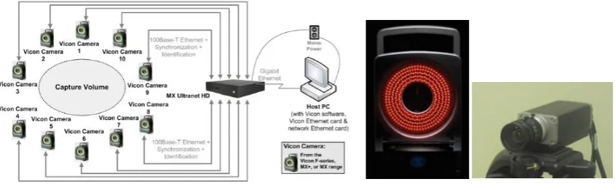
Before the usage of the DV camera will be explained and the new markers will be used by the Vicon system, the hardware of Vicon system has to be discussed. So the terminology of the hardware is known in the rest of the report. The usage and setup of the system will not be discussed here, but can be found in the main manual which can be supplied on request. The main components of the Vicon MX system are:
8 MX‐T160 cameras
The MX camera specifications are 16 Megapixel resolution and a shutter speed up to 100 Hz. Each camera has an infrared ring of lights which will be captured by the camera when reflected by the markers.
1 Basler DV camera
The video camera has a maximum shutter speed 100 Hz and capture the movie files. MX Giganet unit
This MX unit is the connection between the MX cameras, DV camera and other devices such as a force plate, to the host PC. The Giganet can connect up to 10 MX cameras and also another Giganet unit.
MX host PC with Vicon Nexus program
This computer contains the Vicon Nexus program which translates, the 2D data delivered by the MX Giganet unit, into a 3D model
Reflective markers
These spherical markers covered with reflective tape, reflect the infrared light send by the MX cameras. There are two sizes of markers delivered by Vicon which can be attached everywhere, as long as they can be seen by the MX cameras
5 Marker L-frame
This T shaped wand is used for calibrating the system accurately. It is also used to set the origin of the capture volume. It exists out of a T shaped frame with 5 reflecting markers attached on it with known distances between them.
[image:7.595.85.517.504.633.2]5
DV camera
Through problems with the DV camera in the first year of usage of the Vicon MX system, no movie files could be captured and thereby not exported. Also the lack of a good manual for the DV camera made capturing with the DV camera difficult. In Figure 3, it is shown were the program and DV camera is capable of.
In this chapter a Manual will be written for the usage of the DV camera and the exportation of movie files. This manual will also be incorporated in the previous manuals of F. Graafland and A.J. ten Voorde. The purpose of the manual is to show how to make a right overlay video with DV camera and the 3D Data of the markers, which can be exported and used for third parties. The reasons for certain choices will be made clear, wherefore certain options don’t have to be found out again.
Furthermore some examples will be shown of good and bad 3D overlay and the causes of problems will be explained. How to make a capture will not be explained in this report but can be found in the main manual. Also the total setup and the usage of Vicon Nexus can be found in this main manual.
5.1
Extended manual DV camera
Before calibrating and using the DV camera, the motion capture program Vicon Nexus should be started and MX giganet should be switched on.
1. The first step is to adjust the settings of the DV camera in the properties pane of Vicon Nexus. This pane can be found in the bottom of the ‘Resources’ pane, when the DV camera is selected.
File Path:
Browse to a file were you want to save the DV camera Files.
Camera Gain/Brightness:
Adjust till the camera has a clear sharp image.
Sync Source:
MX Giganet 1 – Socket 1
[image:8.595.123.469.197.326.2]This synchronizes the DV camera with MX 3D model.
Sync Source GPO: DV_Normal
This adjusts the frame rate of the DV Camera and so the quality of the movie file. This will also affect the quality of the 3D overlay. For a better/worse quality overlay, select DV_double/DV_halve).
Shutter Speed (ms):
Can be maximum the Frame Rate-1. (Example: 100Hz -> 10 ms)
Focal Length: 6 mm
This is the focal length of this camera.
2. After the DV camera properties have been set, the calibration can start. First the goal of the capture and overlay has to be clear. The origin has to be set as close as possible to the capture subject. When capturing a face or a hand, the origin should be set at this particular height. But when capturing a walking person the origin should be set at the ground. This origin is important, because the DV camera and the 3D model only calibrated “exactly” in the origin. The further away from the origin, the less accurate the overlay is. So when positioning the DV camera, try to get the origin in the middle of the DV camera image towards the bottom. You could also focus the origin in the middle of the y-axis of the image, but you would capture a lot of floor space.
To get a sharper movie of the subject by the DV camera it is not possible to zoom in, but the DV camera can be placed towards the origin of the capture volume.
3. Place the ‘5 Marker L Frame’ in the middle of the capture volume at the appropriate height. Place the DV Camera so the ‘5 Marker L Frame’ can be seen.
4. Go to the ‘Tools’ pane and select the ‘System Preparation’ button. The MX cameras should already been calibrated. If not, this can be found in the overall manual.
5. First set the volume origin for the MX cameras. Go to ‘Set Volume Origin’ and click Start, after a few seconds click the same button again. The origin has been set.
6. Now go to ‘Calibrate DV Cameras’ and click start. Select all 5 markers of the frame with the mouse cursor and click on the same button again. The sequence of picking doesn’t matter.
7. The DV camera appears in the ‘3D Perspective’ now. If calibrated well, it should be on the right place in the capture volume. If not, you must calibrate again.
8. When the calibration is done, it is time for motion capturing. How this is done can be found in the main manual, which can be supplied on request.
9. After capturing and core processing is done, the movie file of the DV camera can be imported in Vicon Nexus. Go to the ‘Pipeline’ tab in the ‘Tools’ pane. Unfold ‘FileIO’ and double click ‘Import AVI’. Select ‘Import AVI’ in the ‘Current Pipeline’ and go to the properties were you can browse to the avi file of the current capture. Select it and run the ‘Import AVI’ pipeline.
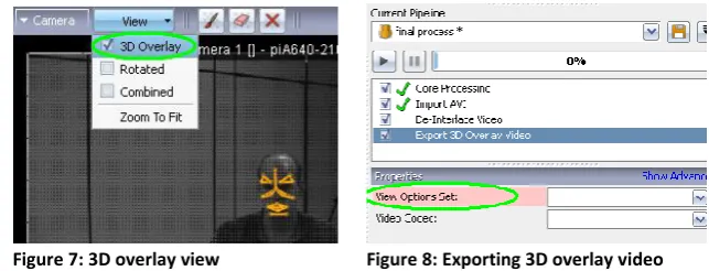
10. Watching the ‘Import AVI’ video in Nexus is possible by opening the ‘Camera’ view and select the DV camera in the ‘Resources’ pane at the ‘System’ tab. To show also the 3D capture select the ‘3D Overlay’ tick in the ‘View’ tab.
11. The overlay video can be exported by selecting the ‘Export 3D Overlay Video’ in the ‘FileIO’ tree. If the DV-Camera is ‘Interlaced’, also the ‘De-interlace Video’ has to be selected. Be aware that this function is above the ‘Export 3D Overlay Video’ in the ‘Current Pipeline’. Select for both operations a Video Codec (the same) and select a ‘View Options Set’.
12. The ‘View Options Set’ can be changed in the top bar by selecting ‘Window’ and then ‘Options’. You can adjust the floor grid, cameras, etc.
13. Now run the Current Pipeline and the overlay video can be found in the same folder as the marker data.
[image:10.595.129.489.120.241.2]Figure 5: Calibrating DV camera using L-Frame Figure 6: 3D perspective camera setup
[image:10.595.121.443.444.567.2]5.2
Examples of overlay videos
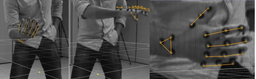
Body overlay
In this case the overlay of the video is not accurate. The coupling between the video and the model near the origin (yellow dot in Figure 9) is good, but when going further upwards to the hip and shoulder, the overlaying becomes worse.
To improve this overlay, the DV camera should focus the origin more in the middle of the image of the camera (x-axis). Regarding the origin compared to the y-axis, the origin should get more upwards. Problem is that the camera should go backwards to still capture the whole subject which isn’t possible in this room.
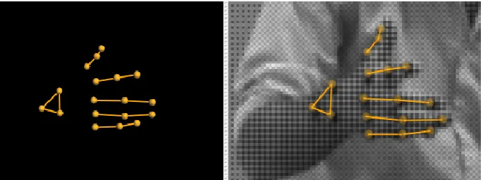
Hand overlay
This overlay is a lot better than the overlay of the total body. The reason for this is the capturing of just a small body part. Also the calibration is done at roughly the right height and the origin is in the middle of image of the camera.
[image:11.595.88.318.238.395.2]Only a few problems occur far away from the origin, as can be seen inFigure 10 b.But this isn’t because of the far distance from the origin.This bad overlaying is due to high moving speed of the hand. To improve this overlaying, the synchronization and bandwidth can be improved. This can be done by setting the Sync Source GPO (5.1 5.1 on DV_Double.
Figure 9: Bad 3D overlay video of human body
[image:11.595.87.512.587.719.2]5.3
Conclusion
6
Testing small markers using normal setup
In the previous report about face captures done by CTI in cooperation with Dr. Quagliato some recommendations were made for capturing the face. A new face model was already made, but problems occurred with the size of the markers. Especially the base of the marker was too big, to attach to small movable parts of the face.
The recommendation was to develop new smaller markers, who could be attached at places like the eyelid, but still could be seen by the Vicon system. To investigate if this is possible, some tests will be performed and examined. If possible, some improvements will be made. First the new markers are subjected to a static test using the normal setup recommended by Vicon. This setup consists out of 8 cameras around the origin at a distance of 3 till 4 meters. The setup can be seen in Figure 6. For the second test, a dynamic capture will be applied using the already created face model. And in the end an eye blink will tried to be captured and examined.
6.1
New markers
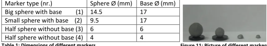
The Vicon system was supplied with two sizes of markers, but with the same sized base. So both markers aren’t useful to attach at small movable places in the face such as the eyelid. The new markers are made of semi spheres which are coated with the same reflecting tape as the markers delivered by Vicon. They were made in the lab of CTI, using a microscope. The markers have no separate base, but because of the semi sphere, the contact area is big enough to attach properly at the skin. The dimensions of the old and new markers are summed up below in Table 1.
Marker type (nr.) Sphere Ø (mm) Base Ø (mm) Big sphere with base (1) 14.5 17
[image:13.595.83.516.493.568.2]Small sphere with base (2) 9.5 17 Half sphere without base (3) 6 6 Half sphere without base (4) 4 4 Table 1: Dimensions of different markers
6.2
Static test
To examine the visibility of the new markers by the Vicon System, a static test will be applied. This will be done for all four markers to compare the visibility of the small markers with the big markers. Also the position will be changed to examine the visibility of the markers at different angles. This could be a problem because of the semi spherical shape of the new markers, which have a different contour from the side. The Nexus Vicon system recognizes a marker only when he sees a round contour. The advantage is that only two MX cameras have to recognize the marker to ensure it is visible in the Vicon Nexus program
In Table 1 behind every marker name, a type number is shown. This type number is used in the remainder of this report to make clear about which marker it’s about.
There are performed three different types test which results are shown below.
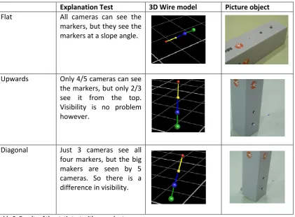
Explanation Test 3D Wire model Picture object
Flat All cameras can see the markers, but they see the markers at a slope angle.
Upwards Only 4/5 cameras can see the markers, but only 2/3 see it from the top. Visibility is no problem however.
[image:14.595.90.512.109.419.2]Diagonal Just 3 cameras see all four markers, but the big makers are seen by 5 cameras. So there is a difference in visibility.
Table 2: Results of the static test with normal setup
6.3
Dynamic test performed on face model
In the previous test it became clear that the small markers, statically, can be seen by the MX cameras with this camera setup. Now the dynamic visibility of the small markers will be examined. This will be done by using an already created face model at the normal setup. When the visibility of the small markers is satisfying, also a new model will be made where the movement of the eyelid tried to be captured.
6.3.1
Face model
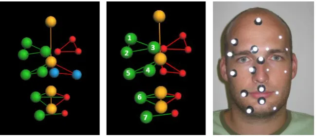
The already created face model existed out of one type of makers. But for these tests will the face model be adapted. The difference is that one side of the model will be created by the big markers type 2 and the other side will be created using the new small markers type 3 and 4. The model is setup like this, because there is only a limited amount of small markers available. The model is shown in Figure 12. The red markers are the small markers whereby the blue ones are the small markers type 4. The green markers are the big markers type 2 with base and they are ordered in a way as is shown in Figure 12 b. This way of ordering is the same for the red makers. The yellow markers don’t play a role in this test.
[image:15.595.86.412.357.498.2]
The visibility of the small markers will be examined with a quantitative test. The test exists out of 3 captures of 10 seconds each. In this time, the face will move and the number of gaps of each marker will be counted. Wrong labeling and the gap time will not be taken into account. An example of a gap can be found in Figure 13. In that case small marker nr 3 (type 3) and small marker nr 5 (type 4) have a gap.
Figure 12 a-b-c: Face model with 3 different types of markers (green red and blue)
The goal of this test is to see, if there is a significant difference in the number of gaps between the big and the small markers and the difference in the number of gaps of the small markers type 3 and 4.
6.3.2
Results
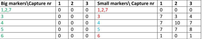
The first goal was to examine the difference between the big markers (2) and the small markers (3 and 4). In Table 3 it is clear to see that the big makers have no visibility problems at all. In comparison, the small markers have a total amount of 62 gaps.
The difference between the small marker type 3 and small marker type 4 is a little less clear, but there is still an observable difference. The markers type 3 and type 4 have an amount of gaps of respectively 16 and 46.
Big markers\Capture nr 1 2 3 Small markers\ Capture nr 1 2 3
1,2,7 0 0 0 1,2,7 0 0 0
3 0 0 0 3 7 3 4
4 0 0 0 4 7 10 7
5 0 0 0 5 7 7 8
[image:16.595.89.518.267.351.2]6 0 0 0 6 1 0 1
Table 3: Amount of gaps of each marker in three captures at the normal setup
6.3.3
Conclusion
Capturing dynamic behavior from a far distance using small markers will cause trouble concerning the visibility. Especially the small markers type 4 have problems, because even when it is attached on a good visible spot (position 5), still a lot of gaps occur. The small marker type 3 could be used though, but can cause some trouble also.
6.4
Dynamic test performed on eyelid
The purpose of the new makers for face capturing was to verify if they could be attached to small movable places and still be visible. In this case, the possibility of capturing the movement of the eyelid will be examined. The previous test, capturing the face movement with small markers, caused problems with the visibility. Especially the small marker type 4 contained a lot of gaps. That is why the capturing of the eyelid will be performed with big markers type 2 and small markers type 3, whereby the small markers will be attached around the eyelid.
Furthermore when the closure of the eye can be seen in the data with this normal setup, the time of an eye blink will be determined. Because there are only a small amount of small markers yet, a model will be made of one eye only.
6.4.1
Eyelid model
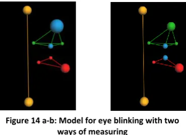
The model exists out of 9 markers with five small markers type 3 (small dots inFigure 14) and four big markers type 2. The small markers are located around the eye. One marker is attached to the eyelid which wasn’t possible with the big markers. The yellow points are just for reference.
If the small markers type 3 are visible, two possibilities to measure the closure of the eye are possible. Both measurements depend on the distance between two markers which are shown in Figure 14. In the first case the distance between the markers will increase when the eye closes and in the second case the distance will decrease when the eye closes.
6.4.2
Results eyelid
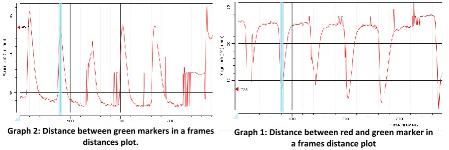
[image:17.595.89.274.341.475.2]The captures of this model were significant for the goal of capturing an eye blink. When the eyes are closed some gaps occur though, but the closure and opening of the eye can be seen in Graph 2 and 2. These results are sufficient to measure the closure time of the eye.
An example of a closed and open eye is shown in Figure 16. Using Vicon Nexus, the distance between selected markers can be shown in a graph. In both cases a peek is shown when the eye closes. Advantage of the Graph 1 (2 green markers) is that it has less gaps then Graph 2 (red and green marker). But for this goal the graphs are both sufficient. The time of an eye blink can easy be seen by overlaying the 3D capture with the Video file. The eye closes and opens at a certain timeframe. Count the amount of frames and the eye blink time is known.
In Table 4, four peaks will be examined for an eye blink. The total time frames of a closure and the distance between the markers will be determined by using the second model.
peak Closure (fr) Distance (mm) Opening (fr) Distance (mm) Time (s)
1e 15 19.7 29 18.2 0.14
2e 77 18.4 89 19 0.12
3th 135 20.4 149 18.2 0.14
[image:18.595.82.519.40.186.2]4th 199 18.1 213 18.1 0.14
Table 4: Blinking time of an eye for four examples
6.4.3
Conclusion eyelid
The first goal, to examine if the markers are still visible when they are placed on a small moving area is succeeded. The eye blink in this case can be captured, though with some gaps. But there is enough information to calculate the time of an eye blink.
The time of an eye blink is approximately 0.14 seconds. For all eye blinking it is nearly the same. The distance between the markers, especially at the closing part of the eye, are less accurate. This can be explained by the fast closure of the eye (steep peak) which can’t be captured exactly because of the bandwidth of the cameras which is 100 Hz (0.01s).
Graph 2: Distance between green markers in a frames distances plot.
Graph 1: Distance between red and green marker in a frames distance plot
[image:18.595.294.490.298.429.2]7
Testing small marker using close setup
The first examinations of using the new markers for face capture, were done with the normal setup, recommended by Vicon. This setup has 8 MX cameras around the capture volume at a distance of 3 till 4 meter. In the previous tests though, it became clear that the MX cameras had some problems to recognize the small markers at dynamic behaviour, especially the smallest type 4 marker. To find out if this problem can be solved by moving the cameras towards the capture volume will be investigated in this chapter. The tests will be performed again, but now with the new setup and also with the smallest markers. If possible, also more difficult examination will be done, when the small markers have good visibility.
7.1
Close setup
For better visibility of the small markers the MX cameras could be moved towards the capture volume. Because the markers at the face can only be seen by the 4/5 MX cameras at the front of the face, not all cameras have to be moved in the new setup. Only 4 MX cameras have to be moved and the other MX cameras can be enabled. The additional advantage is that the files become smaller because fewer cameras mean less data.
Normally when smaller captures have to be made moving the cameras towards the subject is not recommended, especially when using the big markers type 1 and 2. This is due to the fact that, when moving the MX Cameras towards the markers, problems occur with the focus of the lenses. This can’t be adjusted in the Vicon Nexus program, but has to be adjusted on every MX camera. How to build a new setup can be found in Appendix A.
Camera Big marker (1) Small marker (4) 6 (side)
[image:20.595.87.327.451.664.2]8 (front)
Table 5: Examples of proper focusing of MX cameras
When the setup is done properly, the markers should look likeTable 6 You can see that the contour of the small marker, seen by camera 6, isn’t totally round. But the camera still recognizes the marker, as can be seen by the cross.
7.2
Static test
The static test, with all markers on a flat surface, which was applied for the normal setup, will also be applied for the new setup. Only the positions differ a bit. Because the setup is made for face capturing, the static positions that will be examined can be compared with positions of the markers on the face. One position is just in front of all four cameras standing upwards. The second position is the first position with a quarter turn.
Explanation Test 3D Wire model
Front All cameras can see all markers
[image:21.595.87.384.175.424.2]Quarter turn Two cameras can see all markers. The other two don’t see any marker. Two cameras are enough so all markers are still visible.
Table 6: Results of the static test using a close setup
7.3
Dynamic test performed on face model
For the close setup all markers are statically visible, as can be seen in the previous test. For the dynamical visibility the same face capture test will be performed as in paragraph 6.3 . The model can be seen again in Figure 12 and the small markers are at the same place. A quantitative test will be done again and all types of markers will be compared at their visibility. The gathered data will also be compared with data of the previous dynamic test, using the normal setup.
7.3.1
Results
The results of the close distance capture have a little discontinuity concerning the first capture. But for the other two captures the results are nearly the same. The amount of gaps for the big markers (2) and the small makers are respectively 9 and 7. So the visibility off the small markers is better.
The difference between the two kinds of small markers is only one gap, 4 gaps for the type 4 and 3 gaps for the type 3.
Big markers\Capture nr 1 2 3 Small markers\Capture nr 1 2 3
3 1 0 0 3 0 0 1
4 5 0 0 4 4 0 0
5 2 0 1 6 2 0 0
[image:22.595.89.513.318.387.2]1,2,6,7 0 0 0 1,2,5,7 0 0 0
Table 7: Amount of gaps of each marker in three captures at the close setup
7.3.2
Conclusion
Capturing at a close distance, small markers have nearly no problems with visibility. When the first capture will be ignored, because of discontinuities, visibility of all types of makers is nearly the same. So at a close distance usage of small markers is not a problem.
The big makers though could have problems at the close capture setup due to the fact that the cameras are focused on the small markers. If both markers are used for particular capture, try to focus in such a way that both types of marker are sharp enough to see. This is also needed because you want to capture the small markers, but you have to calibrate the MX cameras with the big markers type1 at the L-Frame
In comparison to the normal setup, the performance of the small markers is much better.
7.4
Dynamic test performed on eyelid
The new setup can cope with both types of the new markers. In the previous chapter with the normal setup, a capture was done with a small marker type 3 on the eyelid. This was however, a little irritating for the eye. Because the close setup sees all types of markers, this test will be performed again. But now with the smallest marker type 4 attached on the eyelid.
Furthermore, CTI wants to have the possibility to show customers the full potential and usability of the Vicon Nexus system. So more tests will be performed to show some examples of the do’s and don’ts of the Vicon Nexus system. Because all small markers can be used, an extended model can be made to have more opportunities of examination.
7.4.1
New eyelid model
The new model will exist out of 5 small markers type 3 and 4 small markers type 4. The smallest markers will now be attached on to the upper and lower eyelid of both eyes, as can be seen in Figure 18. The small type 3 markers are attached to the eyebrows and nose. The model exist out of three elements now, as can be seen in Figure 17. Whereby the yellow ellement is relativally static and the green and red elements are the dynamic parts which move when performing an eyeblink.
The tests that will be performed with this model are: Normal eye blinking
Forced eye blinking Frowning
Eye movement when reading
[image:23.595.86.203.361.445.2]Of these different tests, three captures of each test have been made. The results can be found below, wherefore the best captures are used. The first test will also be compared with the eye blinking test from paragraph 6.4 when using the normal setup.
7.4.2
Results eyelid movement
All results of the four tests can be found in this paragraph and made clear by plotting the movement of the eyelid.
Normal eye blinking
The first performed test delivered good and clear results. In one capture not even one gap occurred. The eye blinking time can be examined again, but now for both eyes. Also the data can be compared with the previously gathered data of the normal setup. So, the influence of the two small types of markers can be examined.
In both graphs, the distance between the upper eyelid and the lower eyelid, for the left and right eye are plotted. No other distance between the upper eyelid and the eyebrow, like the normal distance test, had to be plotted because the gathered data was totally clean.
The blinking time of the eye is examined again to see, if the type of marker influences the blinking time. In this case it is done for the green side.
peak Closure (fr) Distance (mm) Opening (fr) Distance (mm) Time (s)
1e 16 19.2 32 18.7 0.16
2e 90 19.3 107 19 0.17
4th 276 18.7 293 19.1 0.17
5th 439 19 455 19.1 0.16
[image:24.595.87.503.214.404.2]Table 8: Blinking time for an eye for four examples Figure 18: Eye closed during an eye
blink
Forced eye blinking
In this case the eye blinking was done on purpose and with more force than a normal eye blink. This was done in rate of once per 2 seconds with a longer closing time. There were performed three captures but only one was satisfying. The results of this experiment can be found below in Graph 4.
The results of these capture contains a lot more gaps in the data, then the previous one but still has enough information to examine the eye blinking time. It is obvious that the eye blinking took a longer time which can be seen in Graph 4. The average time was 0.62 s. This examination was performed at the green side.
peak Closure (fr) Distance (mm) Opening (fr) Distance (mm) Time (s)
1e 30 18.1 88 18.2 0.58
2e 129 17.8 217 18.3 0.88
3th 255 18.4 323 18.4 0.68
[image:25.595.86.385.180.333.2]4th 400 17.6 437 18.2 0.37
Table 9: Eye blinking with force with longer closing time
Frowning
All three frowning captures leaded to a lot of gaps, as can be seen in the Graph 5 shown below. Because the gaps are really big, no good gap filling can be done. Another problem occurs when the markers get visible again and they got labeled incorrectly.
Graph 5: Plot of frowning test with a lot of gaps
Movement eyelid when reading
When someone is reading, the eye will move from left to right. Because it is obvious that no markers can be attached to the eye, this movement will be tried to visualize by the marker movement of the eyelid with respect to other points in the face.
[image:26.595.91.457.140.259.2]The movement of the eye will be tried to visualize in two different ways. The first way, is to determine the distance between the nose marker and the upper eyelid marker, colored blue in Figure 19. The second way is to determine the angle between nose to upper eyelid vector and the lower eyelid to upper eyelid vector (blue makers in Figure 20). These examination are shown for the green part..
In the Graph 6, two peaks can be observed but aren’t there because of the reading. When examining the data with the video overlay the first peak was a rise of the eyelid and the second an eye blink.
Figure 19: Two blue markers for trying to capture reading motion using distance
Figure 20: Three blue markers for trying to capture reading motion using the angle
[image:26.595.83.466.355.531.2]7.4.3
Conclusion eyelid movement
The visibility of the normal eye blinking is not a problem at all. Even when the eye is closed, no gaps occur. So, in comparison to the normal setup, the close setup is preferable, when moving the cameras is no problem.
In comparison to the results of both setups, regarding eye blinking time, the normal setup has a shorter blinking time then the close setup. This is respectively 0.14 seconds for the normal setup, using small markers type 3 and 0.17 seconds for the close setup using the small markers type 4. You would expect that this is reverse, because the smallest markers cause less irritation at the eyelid and should move easier. A possible cause could be the distance between the markers. For the normal setup, the distance when the eye is open and the closing distance are respectively 23 and 19 mm. For the close setup the distance is respectively 20 and 19 mm. So, the eye closes earlier then with the normal setup and so the time blinking time is longer. Comparing this with the literature an eye blink should be, between a 10th and a 5th of a second. When closing the eyes with force, the motion capture has problems to see the small markers at the eyelid. This is due to the fact that the small markers (4) fold into the skin and are not visible anymore. They also tilt a little bit to the ground whereby their semispherical contour changes for the cameras, and so they become unrecognizable. To cope with this problem one or two of the cameras should be installed lower with a more upward angle so they can see the proper contour.
When capturing a frowning person no markers have to be installed at the eyelid because they disappear totally. They‘d better be installed in the middle of the eyebrow then.
8
Discussion
In the discussion all previous conclusion will be summarized with concern to the postulated problem definition and some related problems. Furthermore some recommendations, for better capturing in the future will be given.
8.1
Conclusions
The use of the DV camera had some advantages. Especially with the examination of eye blinking became the video of the DV camera at help. When capturing larger objects, video overlays can be less accurate and so less useful. Unfortunately, there are only limited opportunities to export videos for third parties which can help to analyze the data. You still need access to the Vicon Nexus program to analyze the data using the video. Because when exporting the video, no frame counting is included, which could be useful to isolate the Cartesian data of a particular movement.
Face capturing with small markers can cause problems with the visibility when using the normal setup. Especially the smallest type 4 markers will have a lot of gaps when they tried to be captured with the normal setup. The small type 3 markers could be used with the normal setup, when, for example, a body with face has to be captured. But at places, like the eyelid, this small marker type 3 is still too big for comfort.
That’s why, when capturing only a small object like a face, it is recommended to perform the capture with the close setup. When the cameras are focused properly, the small markers type 3 and 4 have better visibility then the provided markers of Vicon with this setup. The movement of the eyelid can captured really accurate. Only when frowning or blinking to hard, the marker can disappear in a fold of the eye. This is not caused by the camera setup but is the downside of the small sized markers.
The problem with the close setup is that a conflict occurs, when trying to calibrate the MX cameras. You try to focus the MX cameras at the small markers, but calibration is done, by waving with the 5 big markers L-frame. This can be solved to wave with the wand a little further away from the MX cameras and the origin of the capture volume, so the MX cameras can focus at the big markers properly. The capturing, when using the small markers, then can be done at the origin itself.
8.2
Recommendations
More small markers should be available to capture more accurate face movements. This can be done by buying more retro reflective tape to build more small markers or buy the small markers at Vicon.
When setting up the MX cameras for a close capture, don’t place the origin at the wall but in the middle of the room. This prevents problems when trying to calibrate the MX cameras.
9
References
[1] Plug-in Gait Product Guide Foundation Notes Revision 1.0 March 2008
[2] Manual to Use Vicon MX motion capture system, F. Graafland, Centro de Technologia da Informação Renato Archer, Campinas-SP-Brazil (May 2009)
[3] Manual to Use Vicon MX motion capture system, R.A. Miedema, CTI, Campinas – SP – Brazil (January 2010)
[4] Vicon Motion Systems Limited, Vicon MX Hardware System Reference Revision 1.7, Oxford 2007
[5] Vicon, Motion Capture Systems manufacturer www.vicon.com [6] Fujinon, products, DV Camera type DF6HA-1B, focal length www.fujinon.co.jp
10
Appendixes
Focusing the MX cameras
If the face capture has to be done with the new small markers, it is recommended to decrease the capture volume by decreasing the distance of the cameras to the captured subject. Because the markers of a face capture only can seen by 4 or 5 cameras, not all cameras have to be placed towards the subject.
In this case 4 MX cameras will be used for capturing and the other cameras will be enabled. When the cameras are positioned closer towards the markers, the image of the marker can become vague. To sharpen the image, the focus of the lens of the camera has to be adjusted till the image is sharp again. In this Appendix, the procedure to do this will be explained.
Manual for new capturing setup
The first step is to position the four MX cameras and the DV camera around the origin. The origin shouldn’t be placed at the wall but in the middle of the room. This is necessary for calibrating the MX cameras with the ‘5 Marker L-Frame’.
When using four cameras, the setup should be like Figure 21. The MX cameras that will not be used have to be set off in Vicon Nexus. When selected the right MX camera, this can be done in ‘Advanced Properties’ (Figure 23) of the ‘Resources’ pane. Remove the tick in front of ‘Enabled’ and the ‘Enabled LEDs,’ settings and set the ‘Strobe Intensity’ to zero. When properly done, the icon of the MX camera should become yellow and the LEDs of the particular MX camera should be off.
[image:30.595.87.494.268.389.2]Now place a big marker type 1 in the capture volume at the place where the origin will be. If different markers are used, place all these types of markers in the capture volume. Adjust the MX cameras so the markers are in the middle of the image towards the bottom. You can see the image of the camera by selecting the MX camera in Vicon Nexus and select the ´Camera´ view mode. Repeat this procedure for all 4 MX Cameras.
Select the four MX Cameras which are ‘Enabled’ and go to ‘properties’ in the ‘Resources’ pane (Figure 23). Set the ‘Threshold’ between 0.2-0.7 and set the ‘Grayscale Mode’ to All.
To focus the MX Cameras, unscrew the 3 screws of the first ring. (Red arrow Figure 22). Select the right camera in Vicon Nexus and zoom in at the markers positioned in the middle. Now turn the ring until the image becomes sharp (Figure 24). The image of the marker should be white and bright in the middle and a little bit gray at the
border. For a better gray border the threshold also can be fine tuned. Make sure that all markers (especially marker type 1) meet these conditions. When the focus is properly set, tighten the screws again and follow this procedure for the other MX Cameras.
When all MX cameras have been focused, the Grayscale mode should be set to Auto again. To calibrate the system, go to the ‘System Preparation in the ‘Tools’ pane and run the procedure of calibration which can be found in the main manual. If the calibration with the ‘5 marker L-Frame’ doesn’t work, is this due to the fact that the focus isn’t set properly for the biggest marker which is attached at the L frame. To solve this problem, two solutions are at stake. The first one, if possible, is to swing, with the 5 marker L-Frame, further away from the cameras. The second one is to focus the cameras again.
[image:31.595.369.517.72.230.2]When all this steps are done, the capturing can be performed.
[image:31.595.121.483.301.413.2]Figure 23: Properties pane of the DV camera
Figure 25 a-b: Bad focusing for marker type 4 and 1
[image:31.595.100.457.598.666.2]Figure 24 a-b: Good focusing for marker type 4 and 1