ANALYSIS OF THE RESPONSE OF A
LAMINATE TO IMPOSED FORCES
USING CLASSICAL LAMINATION
THEORY AND FINITE ELEMENT
TECHNIQUE
VINAY .S .KALE1*
P.G. Student ME (CAD/CAM/CAE) 1
Rajarambapu Institute of Technology, Sakharale 415414, Maharashtra, India. [email protected]
N.K.Chhapkhane2*
2
Professor, Rajarambapu Institute of Technology, Sakharale 415414, Maharashtra, India. [email protected]
Abstract
The laminate is a two or more lamina bonded together to act as an integral structural element. The laminae are combined to create a laminate. Classical lamination theory consists of a collection of mechanics of materials type of stress and deformation hypothesis. By use of classical lamination theory we can consistently proceed directly from the basic building block, the lamina, to the end result, a structural laminate. The classical lamination theory is very important in analysis of laminate because it will predict the stresses, strains, forces and moments relationships with reasonable accuracy. The composite materials are widely used in military aircraft, civil aircraft, space and automobile applications. ANSYS 11software is used for analysis of composite laminate. First order shear stress deformation theory is used for the analysis of laminate in finite element technique.
Keyword: - classical lamination theory, interlaminar shear stress, FEA.
1. INTRODUCTION
A Laminate is a two or more laminae bonded together to act as an integral structural element. The various laminae are oriented with principal material direction at different angles to global laminate axes to produce a structural element capable of resisting load in several directions. The reason laminae are combined to create a laminate is to achieve the largest possible bending stiffness for material used. The composite materials are widely used in military aircraft, civil aircraft, space and automobile applications. For analysis of laminate, the classical lamination theory is used. The classical lamination theory consists of a collection of mechanics of materials type of stresses and deformation hypothesis. By use of this theory, we can consistently proceed directly from the basic building block, the lamina, to the end result, a structural laminate. The bond between a laminate are presumed to be infinitesimally thin as well as non shear deformable. That is, the displacements are continuous across lamina boundaries so that no lamina can slip relative to another. The classical lamination theory is very important in analysis of laminate because it will predict the stresses, strains, forces and moments relationships with the reasonable accuracy. The obtained result from the classical lamination theory are compared with a presently available finite element method, using ANSYS software. With the FEM method, the layered configuration is defined layer-by-layer from bottom to top. The bottom layer is designated as layer 1, and additional layers are stacked from bottom to top in the positive Z (normal) direction of the element coordinate system.
Composites exhibit several types of coupling effects, such as coupling between bending and twisting, coupling between extension and bending, etc. This is due to stacking of layers of differing material properties. Interlaminar shear stresses are usually important at the free edges of a model. For relatively accurate interlaminar shear stresses at the free edge locations, the element size at the boundaries of the model should be approximately equal to the total laminate thickness.
.Classical Lamination Theory
2.1 Assumption in Classical lamination theory. Each lamina is orthotropic.
Each lamina is homogeneous
A line straight and perpendicular to middle surface remains straight and perpendicular to middle surface during deformation.
The laminate is thin and is loaded only in its plane(plane stress)( 0
Displacements are continuous and small throughout the laminate
Each lamina is elastic
No slip occurs between lamina interfaces.
2.2 Lamina stress strain behavior
The stress strain relations in principal material coordinate for lamina of an orthotropic material under plane stresses are,
=
0 0
0 0 (1)
The reduced stiffnesses, Qij, are defined in terms of engineering constant Q11= Q22 =
Q12 = = ; Q66 = G12 In any other coordinate system in the plane of lamina, stresses are
(2) Where,
= cos + 2( +2 ) sin sin
=( 4 sin sin cos
= sin 2 +2 ) sin cos
2 sin + ( 2
= 2 + ( 2 sin
= ( 2 2 sin sin cos
2.3 Stress and strain variation in a laminate
Fig.2.3.1 Geometry of deformation of x-z plane
The laminate strains have been reduced to , , and by virtue of the Kirchhoff hypothesis.
= + z (3)
Where the middle surface strain are
= (4)
And the middle surface curvatures are
2
(5)
The Kirchhoff hypothesis has been readily verified to imply a linear variation of strain through laminate thickness. Because the strain in the equation have the form of straight line i.e. y= mx + b. By substitution of the strain variation through thickness, in the stress-strain relations, the stresses in the layer can be expressed in terms of the laminate middle surface strains and curvatures as
= (6)
Where and zk-1are defined in basic laminate geometry of fig 2.3.2.Note there that the zi are directed distance(coordinates) in accordance with convention that z is positive downward. That is, zk is the directed distance to the bottom of layer, and zk-1is the directed distance to the top of layer. Moreover, z0= ⁄2,
Fig .2.3.2 Geometry of an N-layered laminate
2.4 Resultant laminate forces and moments
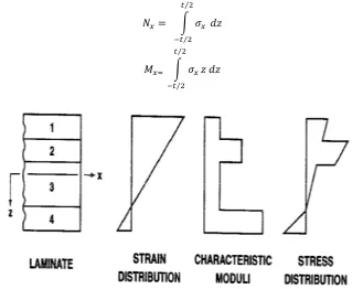
The resultant forces and moment acting on a laminate are obtained by integration of stresses in each layer or lamina through the laminate thickness, for example,
⁄
⁄ ⁄
⁄
Fig.2.3.3 Hypothetical variation of strain and stress through laminate thickness
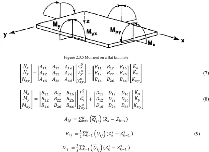
Similarly Mx is a moment per unit width has shown in figure 2.3.5. However, Nx, etc., will be referred to as forces and moments with the stipulation of per unit width being dropped for convenience.
Figure 2.3.5 Moment on a flat laminate
= (7)
(8)
∑
∑ (9)
∑
In equations (7), (8) and (9), the Aij are extensional stiffnesses, the Bij are bending extension coupling stiffnesses and Dij are bending stiffnesses.
3. Calculation of stress by using Classical Lamination Theory.
Material properties
[GPa] 133.86
[GPa] 7.706
[GPa] 4.306
[GPa] 2.76
0.301 0.396
ρ [g/ ] 1.52
Table 1 Material properties of unidirectional carbon/epoxy composites
For five layer laminate (0/90/0/90/0):-
Length 500mm Width 500mm Number of layers(plies) 5
Single ply thickness 0.5 mm
Total plate thickness 2.5mm
Table 2 Full size Plate geometry for five layers
= ; =
134.5 2.33 0 2.33 7.746 0
0 0 4.306
= ; =
7.746 2.33 0 2.33 134.6 0
0 0 4.306 X10
3.1 Extensional stiffness matrix
=
209.58 5.825 0 5.825 146.17 0
0 0 10.765 X10
3.2 Bending extension coupling stiffness
=
0 0 0 0 0 0 0 0 0 3.3 Bending stiffness
D =
140.73 3.02 0 3.02 44.4 0
0 0 5.59
=
500 500
0 =
209.56 5.825 0 5.825 146.17 0
0 0 10.76 10 +
0 0 0 0 0 0 0 0 0
00 0
0 0 0 0 0 0 0 0 0
140.73 3.02 0 3.02 44.4 0
0 0 5.59
3.4 Calculation of stresses 3.4.1 For θ =
X
=
134.56 2.33 0 2.33 7.746 0
0 0 4.306
10 2.293.44 0 10
=
316.15 31.98
0
10 ⁄
3.4.2 For θ =
X
=
7.746 2.33 0 2.33 134.56 0
0 0 4.306 10
3.45 6.405
0 10
= 25.75 468.22
4. Calculation of laminate stresses by using Finite Element Analysis 4.1 Steps in FEA
4.1.1Model generation
Main menu > Preprocessor > structural > ok
Preprocessor > Element type > shell > 8 node281> ok
Preprocessor > Material property > material model > Orthotropic material Preprocessor > section >shell >layup >add/edit
Preprocessor > modeling > create >area >rectangle > by dimension >apply Preprocessor >meshing > manual size > esize >apply
Preprocessor > mesh >area > mapped >3 or 4 sided > apply 4.1.2 Solution
Load >def. load > apply >structural >displacement > on node > apply Load >def. load > apply >structural >forces/moments > on node >apply Solution > solve > current LS > ok
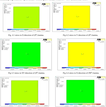
4.1.3 Postprocessing
General postprocessor >plot result >contor plot >nodal solution > X directional stress General postprocessor >plot result >contor plot >nodal solution > Y directional stress General postprocessor >plot result >contor plot >nodal solution > XY directional stress
Fig. 4.1 stress in X direction of (0) lamina. Fig 4.2 stress in Y direction of (0) lamina.
Fig 4.3 stress in XY direction of (0) lamina. Fig 4.4 stress in X direction of (90 ) lamina.
5. Comparison of results for (0/90/0/90/0) laminate.
PLY
ORIENTATION STRESS
ANALYTICAL
( ⁄ ) FEA( ⁄ ) % ERROR
0
316150 313954 0.6946
31980 31274 2.2076
0 0 0
90
25750 25350 1.5533
468220 450844 3.7110
0 0 0
0
316150 313954 0.6946
31980 31274 2.2076
0 0 0
90
25750 25350 1.5533
468220 450844 3.7110
0 0 0
0
316150 313954 0.6946
31980 31274 2.2076
0 0 0
6. Conclusion
The classical lamination theory is very important in analysis of laminate because it will predict the stresses, strain, forces and moment relationship with accuracy. Composites exhibit several types of coupling effect, such as coupling between bending and extension. The bond between a laminate is thin and non shear deformable hence the displacement are continuous across the lamina boundary so that no lamina can slip relative to another.
Finite element analysis of orthotropic laminated composite plate is carried out using refined first order shear deformation theory. The stacking sequence has a significant effect on the normal stress through the thickness of laminate. The classical lamination theory has been used in the stress analysis of composite laminate. However it is observed that classical lamination theory is only accurate for thin composites laminates. As the thickness of lamina increases the shear effect becomes predominant and CLT and FEA results do not match each other. Laminate thickness, material properties are symmetric about middle surface of laminate, so there is no coupling between bending and extension. Because in classical lamination theory the are directed distance (coordinates) in accordance with convention that z is positive downward with reference to the middle surface and negative upward with reference to middle surface.
7.REFERENCES
[1] Robert. M. Jones “Mechanics of composite materials” second edition, Taylor and Francis, 1999
[2] P.K.Mallick “Fiber reinforced composites material, manufacturing and design” third edition, Taylor and Francis. [3] Ever J. Barbero “Finite element analysis of composite materials” Taylor and Francis, 2011
[4] T. Pervez, A.C. Seibi, F.K.S. Al-Jahwari “Analysis of thick orthotropic laminated composite plates based on higher order shear deformation theory” Composite structures71(2005)414-422
[5] Thuc Phuong Vo and Jaehong Lee “Flexural–torsional behavior of thin-walled closed-section composite box beams” Engineering Structures 29 (2007) 1774–1782.
[6] Reaz A. Chaudhuri “Analysis of laminated shear-flexible angle-ply plates” Composite Structures 67 (2005) 71–84. 27 February 2004. [7] R.G. Reid and R. Paskaramoorthy. “An extension to classical lamination theory for use with functionally graded plates” Composite
Structures 93 (2011) 639–648.
[8] R.sturzenbecher and K. Hofststter “Bending of cross-ply laminated composites: An accurate and efficient plate theory based upon models of Lekhnitskii and Ren.” Composite Structures 93 (2011) 1078–1088.
[9] Hamidreza Yazdani Sarvestani and Mohammadreza Yazdani Sarvestani. “Interlaminar stress analysis of general composite laminates” International Journal of Mechanical Sciences 53 (2011) 958–967.26 July 2011.
[10] Oualid Limam and Gilles foret “Ultimate strength of free-edge composite laminates under tensile loading: A limit analysis approach”. Composites: Part B 37 (2006) 286–291. 5 January 2006.
[11] W.Van Paepegem. “Modeling the nonlinear shear stress–strain response of glass fibre-reinforced composites”. Composites Science and Technology 66 (2006) 1455–1464. 4Jun2005.