Review paper
MRI-guided lung SBRT: Present and future developments
Martin J. Menten, Andreas Wetscherek, Martin F. Fast
⇑
Joint Department of Physics at The Institute of Cancer Research and The Royal Marsden NHS Foundation Trust, London, UK
a r t i c l e i n f o
Article history: Received 4 October 2016
Received in Revised form 25 January 2017 Accepted 7 February 2017
Available online xxxx
Keywords: Lung cancer SBRT
Hypo-fractionation MRI guidance Adaptive radiotherapy
a b s t r a c t
Stereotactic body radiotherapy (SBRT) is rapidly becoming an alternative to surgery for the treatment of early-stage non-small cell lung cancer patients. Lung SBRT is administered in a hypo-fractionated, confor-mal manner, delivering high doses to the target. To avoid norconfor-mal-tissue toxicity, it is crucial to limit the exposure of nearby healthy organs-at-risk (OAR).
Current image-guided radiotherapy strategies for lung SBRT are mostly based on X-ray imaging modal-ities. Although still in its infancy, magnetic resonance imaging (MRI) guidance for lung SBRT is not exposure-limited and MRI promises to improve crucial soft-tissue contrast. Looking beyond anatomical imaging, functional MRI is expected to inform treatment decisions and adaptations in the future.
This review summarises and discusses how MRI could be advantageous to the different links of the radiotherapy treatment chain for lung SBRT: diagnosis and staging, tumour and OAR delineation, treat-ment planning, and inter- or intrafractional motion managetreat-ment. Special emphasis is placed on a new generation of hybrid MRI treatment devices and their potential for real-time adaptive radiotherapy.
Ó2017 Associazione Italiana di Fisica Medica. Published by Elsevier Ltd. This is an open access article under the CC BY-NC-ND license (http://creativecommons.org/licenses/by-nc-nd/4.0/).
Contents
1. Introduction . . . 00
1.1. The clinical rationale for lung SBRT . . . 00
1.2. Current clinical workflow for lung SBRT . . . 00
1.3. MRI-guided lung SBRT . . . 00
2. Technical implementations of MRI scanners into the radiotherapy workflow . . . 00
2.1. Offline MRI. . . 00
2.2. Online MRI. . . 00
3. Opportunities for MRI to enhance the lung SBRT workflow . . . 00
3.1. Diagnosis and staging . . . 00
3.2. Delineation, dose calculation and treatment planning . . . 00
3.3. Patient setup and interfractional adaptations . . . 00
3.4. Intrafractional motion management . . . 00
4. Conclusion and outlook . . . 00
Acknowledgements . . . 00
References . . . 00
1. Introduction
1.1. The clinical rationale for lung SBRT
Lung cancer is the most common type of cancer, with non-small
cell lung cancer (NSCLC) representing the majority of cases
[1,2]
.
Within this patient cohort, roughly 15–20% present with an early
and localised form of the disease (stage I), indicating a lack of nodal
involvement and metastatic spread. The recent roll-out of
wide-scale, low-dose computed tomography (CT)-assisted screening
might further increase the number of patients diagnosed at an
early disease stage. Traditionally, surgery is the treatment method
of choice for these patients
[3]
. However, some patients are
classi-fied as
medically inoperable
due to comorbidities, or they decline
surgery for other reasons.
http://dx.doi.org/10.1016/j.ejmp.2017.02.003
1120-1797/Ó2017 Associazione Italiana di Fisica Medica. Published by Elsevier Ltd.
This is an open access article under the CC BY-NC-ND license (http://creativecommons.org/licenses/by-nc-nd/4.0/).
⇑
Corresponding author at: Department of Radiation Oncology, Netherlands Cancer Institute, Amsterdam, The Netherlands.E-mail addresses: [email protected] (M.J. Menten), [email protected] (M.F. Fast).
Contents lists available at
ScienceDirect
Physica Medica
j o u r n a l h o m e p a g e : h t t p : / / w w w . p h y s i c a m e d i c a . c o m
In the past, the alternative treatment option of prescribing
con-ventionally fractioned radiotherapy resulted in worse outcome
compared to surgery, mainly due to the lack of local control
[4]
.
Taking heed from cranial radiosurgery, stereotactic body
radiother-apy (SBRT) aims at delivering fewer, but more intense radiotherradiother-apy
fractions (hypo-fractionation). Several studies have shown that
increasing the biologically effective dose above 100 Gy decreases
the number of patients with local failures and increases overall
survival in early-stage NSCLC patients compared to conventionally
fractionated radiotherapy
[5]
, leading to SBRT being the new
stan-dard of care for inoperable early-stage NSCLC patients.
Traditionally, only patients with tumours located at least 2 cm
away from the proximal bronchial tree are considered for SBRT
[6]
. This pre-selection of eligible patients intends to minimise
bronchial toxicities, but it also severely limits treatment options
for inoperable early-stage NSCLC patients with more centrally
located tumours
[7]
. More recently, trials were set up to identify
a slightly milder form of hypo-fractionation suitable for these
patients
[8]
. Furthermore, SBRT is being investigated for the
treat-ment of oligometastatic lung cancer
[9,10]
and small cell lung
can-cer
[11]
.
1.2. Current clinical workflow for lung SBRT
While SBRT aims at delivering high doses to the target, it is
cru-cial to limit the exposure of nearby healthy organs-at-risk (OAR),
including surrounding lung tissue, the brachial plexus, spinal cord,
trachea, proximal bronchial tree, oesophagus, heart and great
aor-tic vessels, liver and ribs
[12]
. An additional challenge for the
radio-therapy of lung tumours are inter- and intrafractional anatomical
changes
[13]
.
After diagnosis, staging and treatment decision, the clinical
radiotherapy workflow begins with the acquisition of a planning
CT scan. Accurate delineation of the tumour and nearby OAR in this
image is crucial, as a treatment plan is created based on these
con-tours. Today, many institutions utilise modern delivery techniques
for
SBRT,
such
as
intensity-modulated
radiotherapy
and
volumetric-modulated arc radiotherapy
[14–16]
. In conjunction
with inverse treatment plan optimization it is possible to design
highly conformal dose distributions, even in inhomogeneous
ana-tomies
[17,18]
.
In order to ensure correct delivery of the treatment plan, utmost
attention is paid to precise patient positioning for each fraction, for
example by using body frames for fixation
[19]
. About 10–15 years
ago, volumetric X-ray imaging started being integrated with
mod-ern linear accelerators (linacs)
[20–22]
. Utilising the provided
imaging information, the patient can be rigidly shifted to position
the target inside the treatment beam
[23,24]
. Implanted fiducials
often support this process. In addition to rigid shifts, the patient’s
body may deform between fractions due to weight loss, tumour
growth or shrinkage, or volume changes of healthy organs. The
vol-umetric images acquired prior to each fraction can be used to
eval-uate whether the original treatment plan is still suitable after
interfractional motion. If not, a substitute plan can be created,
either based on a newly acquired simulation CT scan or using the
in-room images themselves
[25,26]
.
Intrafractional motion during treatment delivery, such as
respi-ratory and cardiac movement, may cause the anatomy to shift or
deform up to several centimetres
[13]
. Using a 4D CT scan for
treat-ment planning allows the consideration of breathing motion by
deploying either an internal target volume (ITV), mid-ventilation
or mid-position approach
[27–29]
. However, all these methods
are based on extended treatment margins and the characteristics
of the target motion can change over the course of the treatment
[30]
. Breathing protocols attempt to reproduce a certain
anatomi-cal state during treatment delivery by having the patient hold its
breath, either voluntarily
[31]
or aided by an active breathing
con-trol device
[32]
. Gating turns off the treatment beam if the target
leaves a previously defined volume
[33]
. Both these strategies
result in an increased treatment time and reduced patient comfort.
More advanced techniques aim at adapting the treatment in
real-time by either moving the entire linac
[34]
, tilting the treatment
head
[35]
, repositioning the patient using a robotic treatment
couch
[36,37]
, or by changing the treatment beam’s position and
shape by moving the leaves of the linac’s multi-leaf collimator
(MLC)
[38–40]
. Most of these techniques have been used to deliver
real-time adapted lung SBRT
[41–43]
. They all require real-time
information about the patient’s anatomy. This can be obtained by
monitoring either internal or external surrogates and correlating
them with the tumour motion
[44]
. The tumour can also be
loca-lised using MV portal imaging
[45,46]
or kV fluoroscopy
[47,48]
.
Automated localisation is often aided by fiducial markers,
surgi-cally inserted in or near the target. Another marker-based method
detects implanted resonant circuits using an electromagnetic array
[49]
.
1.3. MRI-guided lung SBRT
Despite these advances in lung SBRT delivery technique, there
are still residual uncertainties. MRI offers better soft-tissue
con-trast than CT or cone-beam CT (CBCT), does not expose the patient
to additional imaging dose, and offers a larger variety of functional
imaging capabilities. For this reason, there has been an increased
interest in harnessing MRI for radiotherapy of different cancer
sites, including lung. This has the potential to enhance several
aspects of the lung SBRT workflow, including:
diagnosis and staging (Section
3.1)
,
delineation of the tumour and OAR for treatment planning
(Section
3.2)
,
accurate patient setup and adaptation of the treatment to
inter-fractional anatomy changes (Section
3.3)
,
monitoring of intrafractional motion and real-time adaptation
of the delivery (Section
3.4
).
Decreasing the uncertainties in these areas allows shrinking the
treatment margins while maintaining dose coverage of the target.
Consequently, reduced toxicities in normal-tissue for lung SBRT,
and, ultimately, the expansion of the SBRT to more central lung
tumours can be surmised.
This review first introduces the various technical
implementa-tions of MRI scanners into the radiotherapy workflow (Section
2
).
Afterwards, it discusses the different areas where MRI is already
enhancing lung SBRT treatments or might do so in the future
(Sec-tion
3
). It is important to keep in mind that MRI-guided lung SBRT
is still in its infancy and that the number of directly related
publi-cations is therefore limited.
2. Technical implementations of MRI scanners into the
radiotherapy workflow
2.1. Offline MRI
To employ MRI for diagnostic, staging and treatment simulation
purposes, having a stand-alone MRI scanner at the same institution
can suffice. However, when using MRI for patient setup and
inter-fractional treatment adaptation, identical patient positioning
dur-ing imagdur-ing and treatment becomes crucial. One way to ensure
this relies on the transport of the patient between linac and MRI
scanner, located in different rooms, on a trolley system using a
shared table top and immobilisation device (see
Fig. 1
)
[50,51]
.
Another option is to shuttle the MRI scanner on ceiling-mounted
rails into and out of the treatment room (see
Fig. 2
)
[52]
. Both
sys-tem designs ensure that the magnitude of electromagnetic
cross-interference is reduced to a minimum by using spatial separation.
2.2. Online MRI
Offline MRI solutions cannot monitor intrafractional anatomical
changes and the patient might move between imaging and
Fig. 1.Three photographs of the shuttle-based MRI-guided radiotherapy solution at Umeå University, Sweden. A movable treatment table and patient fixation system can be attached to either imaging or treatment device. Reprinted from International Journal of Radiation Oncology*Biology*Physics, 74(2), M. Karlsson, M.G. Karlsson, T. Nyholm, C. Amies, B. Zackrisson, Dedicated Magnetic Resonance Imaging in the Radiotherapy Clinic, pp. 644–51, Copyright (2009), with permission from Elsevier.
Fig. 2.(A) Floor plan of the MRI-guided facility at Princess Margaret Hospital, Toronto, Canada. (B) The MRI-scanner is attached to rails on the ceiling and can be moved either into the brachytherapy or radiotherapy suite prior to treatment. Reprinted from Seminars in Radiation Oncology, 24(3), D.A. Jaffray, M.C. Carlone, M.F. Milosevic, S.L. Breen, T. Stanescu, A. Rink, H. Alasti, A. Simeonov, M.C. Sweitzer, J.D. Winter, A Facility for Magnetic Resonance–Guided Radiation Therapy, pp. 193–95, Copyright (2014), with permission from Elsevier.
treatment. For this reason, there are considerable efforts to
inte-grate MRI directly with the treatment unit.
The first commercially available MRI-guided treatment system,
based on irradiation with three
60Co sources, has been developed
by ViewRay Inc., Cleveland, OH, USA
[53]
. The system has been
used to treat patients since early 2014, including lung cancer
patients with SBRT
[54]
. Several research groups/vendors have
been working on combining a linac with MRI (see
Fig. 3
)
[55–58]
.
Machine design has to warrant correct functioning of both
imaging and treatment system in the presence of electromagnetic
cross-interference. The choice of beam source and main magnet as
well as the orientation and movement of all the components
rela-tive to each other directly influences the dose delivery and imaging
capabilities. There are considerable differences between systems
with regard to treatment beam properties, such as beam energy,
penumbra, field-of-view and MLC leaf width at isocenter, and the
strength and orientation of the main magnetic field (see
Table 1
).
In addition to beam properties, the dose delivered to the patient
is affected by the B
0magnetic field, which is present at all times.
While the primary photon beam is not influenced, the Lorentz
force deflects secondary electrons onto a curved trajectory. This
electron return effect (ERE) is more pronounced at higher B
0field
strengths and distorts the dose especially at air-tissue-interfaces,
which present themselves manifold in thoracic anatomy
[59]
.
Signal- and contrast-to-noise ratio as well as spatial fidelity of
the images are affected by the strength and homogeneity of the
B0 magnetic field as these govern the relaxation times of the MRI
signal. Due to lung tissue’s inherently low T2* relaxation time,
lower field strengths can be beneficial when attempting to image
thoracic anatomies
[60]
.
3. Opportunities for MRI to enhance the lung SBRT workflow
Table 2
provides an overview of the most commonly employed
sequences for lung MRI. The table is condensed from the
recom-mendations in
[63,64]
and annotated with radiotherapy
applica-tion in mind. Fast spin echo (FSE) sequences are typically
acquired using respiratory gating, which is prone to artefacts
caused by irregular breathing or cardiac motion. Balanced
steady-state
free
precession
(bSSFP)
sequences
exhibit
a
T2/T1-weighted contrast and a high signal-to-noise ratio, but can
suffer from banding artefacts in peripheral areas of the image,
which is problematic if body contours are needed for treatment
planning. The traditional limitations of diffusion-weighted (DW)
MRI could be overcome by moving away from the echoplanar
imaging readout to a segmented readout scheme
[65]
.
3.1. Diagnosis and staging
In order to be eligible for lung SBRT, patients must present at an
early disease stage, meaning that only small, localised lesions are
Fig. 3.MRI-guided treatment units developed by different research groups/vendors. (A) The ViewRay MRIdian, the first clinical system at Washington University, St. Louis, MO, USA (image courtesy of P.J. Parikh), (B) the 1.5 T MR-linac developed by Elekta AB installed at NKI-AvL, Amsterdam, The Netherlands, (C) the linac-MR prototype (v1) at Cross Cancer Institute, Edmonton, Canada (image courtesy of B.G. Fallone, www.linacMR.ca), and (D) the MRI-linac prototype developed by the Australian MR-linac program, located at the Ingham Institute, Liverpool, Australia (image courtesy of G.P. Liney on behalf of the Australian MRI-Linac Program).
Table 1
System characteristics of the most common hybrid MRI radiotherapy machines. B0orientation is specified relative to the treatment beam direction.
Treatment unit Treatment beam(s) Magnet design B0[T] B0orientation Additional comments
ViewRay MRIdian[53] Three60Co sources Split 0.35 Perpendicular Replacement of60Co sources with a linac under development Elekta MR-linac[55] 7 MV linac Closed 1.5 Perpendicular Beam traverses cryostat and magnet
Canadian linac-MR (v2)[61] 6 or 10 MV linac Split 0.5 Inline Magnet rotates with gantry
Australian MRI-linac[57] 4 or 6 MV linac Split 1.0⁄ Inline or perpendicular Both B0orientations under investigation
⁄The current research version uses a 1.5 T closed magnet[62].
existant without any nodal or metastatic spread. Currently,
com-bined multi-slice CT and
18Fludeoxyglucose (FDG) positron
emis-sion tomography (PET), in addition to biopsies, are considered
the gold standard for staging
[66]
. However, biopsy procedures
pose an additional burden to the patient and their execution is
challenging for small, peripheral tumours
[3]
. Although the use
of PET-CT is well established, the relatively low spatial resolution
and motion artefacts, resulting from long acquisition times, are
prevalent issues
[67,68]
. Furthermore, inflammatory areas in the
lung can lead to increased FDG uptake and the diagnosis of false
positives. MRI could play a role in staging
[69,70]
and
MRI-derived motion information in hybrid PET-MRI devices could be
used to mitigate PET motion artefacts
[71,72]
.
In order to determine size and extent of tumour growth with
MRI, a range of acquisition techniques has been deployed, for
example standard T1- or T2-weighted acquisitions, 2D cine MRI,
or single-shot FSE MRI
[73,74]
. T2-weighted, dynamic
contrast-enhanced (DCE), or DW MRI have proven promising in their ability
to distinguish between benign and malignant tumours
[75–78]
.
Identifying disease spread to lymph nodes is difficult using
PET-CT due to its limited spatial resolution
[68]
. Several MRI sequences
have been investigated to stage mediastinal and hilar lymph node
metastases
[79–81]
. A recent meta-analysis of twelve studies has
concluded that MRI offers an improved sensitivity and accuracy
over PET-CT
[82]
.
It remains to be seen whether MRI can complement the
ubiqui-tous FDG-PET for diagnosis and staging of lesions. The higher
spa-tial resolution of MRI could prove beneficial for staging and
detection of smaller nodes and metastases that could go
unde-tected in PET-CT.
3.2. Delineation, dose calculation and treatment planning
Currently, treatment simulation for lung SBRT is mostly based
on CT images. The introduction of PET-CT for target definition
has led to a significant decline in delineation uncertainties
com-pared to CT-only contouring
[83]
. It remains to be seen whether
the introduction of MRI for target delineation purposes will result
in any additional benefit. Delineation uncertainties are larger for
OAR as CT features relatively poor soft-tissue contrast (see
Fig. 4
), resulting in uncertainties of up to a few centimetres for
the oesophagus and spinal cord
[84]
. The improved soft-tissue
con-trast of MRI may lead to a reduction in contouring variability for
these structures.
When using MRI for treatment planning purposes, it is crucial to
ensure spatial fidelity of the image data
[85]
. One potentially
crit-ical issue is the local differences in tissue susceptibility that can
induce geometric distortions. For lung tissue, this effect can result
in maximum distortions of up to 4 mm, depending on main
mag-netic field strength, orientation and gradient field strength
[86]
.
However, mean geometric distortions were found to be
substan-tially lower (
6
1 mm). It should be noted that these errors are in
addition to other distortions induced by non-linearities in the main
magnetic and gradient field. Recently, the composite 4D distortion
effect induced by scanner and susceptibility distortions was
inves-tigated for mobile lung tumours of different sizes
[87]
. Composite
distortions were considered manageable (
6
1 mm), even for
high-field MRI scanners as long as these were operated in combination
with high readout bandwidth at the cost of increased noise
[88]
.
While not available on all vendor platforms, non-cartesian
k-space trajectories, such as a radial or PROPELLER acquisition, can
be employed for robustness against motion artefacts
[89,90]
.
Similarly to 4D CT and 4D CBCT – albeit not as established – 4D
MRI can be used to evaluate periodic anatomical changes due to
breathing. 4D MRI can be either obtained based on repeated
acquisition of slices covering the whole volume and respiratory
cycle
[91–93]
or using a continuous 3D acquisition with
sophisti-cated reconstruction techniques
[94–96]
. While 4D MRI based on
2D acquisitions is more easily available, the 3D-based techniques
offer higher resolution and allow for a full 3D distortion correction.
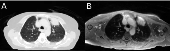
Fig. 4.(A) CT image and (B) T1-weighted MR image acquired with an ultra-fast gradient echo sequence of a NSCLC patient with a tumour located in the left upper lobe. While the bones and lung tissue are better recognizable on the CT image, the soft-tissue contrast of the MR image is superior, especially with respect to the mediastinum. Table 2
MRI sequences for lung cancer imaging (adapted from[63,64]).
Sequence Strength Acquisition type Spatial resolution Distortion risk Variants Comments
Volumetric T1w GRE Nodules Breath-hold High Low Dixon, 4D Low contrast
T2w single-shot FSE Infiltrative disease Breath-hold Low – moderate
Low Cine –
T2w gated FSE Mediastinal structures, infiltrative disease
Respiratory gated Moderate – high
Moderate Dixon, volumetric
Long acquisitions
T2/T1w bSSFP Lung function Free-breathing Moderate –
high
Moderate Cine, 4D Banding artefacts
T1w FSE Mediastinal lymph nodes Multiple breath-hold
Moderate Moderate DCE –
DWI Dose painting Multiple
breath-hold
Low High – Distortion risk reduction
possible
Abbreviations: GRE = gradient echo; DCE = dynamic contrast-enhanced; FSE = fast spin echo; T1w/ T2w = T1/ T2-weighted; bSSFP = balanced steady-state free precession; DWI = diffusion-weighted imaging.
A conceptual limitation of 4D scans is that they average over several
respiratory cycles and thus cannot accurately depict baseline shifts
of breathing motion
[97,30]
. MRI could be utilised to acquire 2D cine
MR images that provide a better visualisation of the patient’s
breathing, especially with regard to irregularities. Combining 4D
MRI with 2D cine MRI using a PCA-based approach allows
genera-tion of 3D deformable vector fields with a temporal resolugenera-tion of
476 ms
[93]
. In the future, this temporally resolved observation of
the tumour motion could be used to define adequate treatment
margins.
One obstacle for the widespread introduction of MRI for
treat-ment planning is the absence of electron density and attenuation
coefficient information in the MR images. Commonly, this lack of
information is circumvented by either generating synthetic
(referred to as
pseudo
from here on) CT images from MR images
employing Dixon methods, or by (deformably or rigidly)
register-ing the MR image to a treatment plannregister-ing CT. The accuracy of
the latter approach depends on the quality of the registration.
While the generation of pseudo-CT images works well for
rela-tively homogeneous treatment sites, such as prostate or brain
[98]
, it is more problematic in the thoracic region, where both lung
and bone feature very little MR signal. Correctly accounting for
bone and lung tissue during treatment planning is key for
achiev-ing the desired dose distribution in the patient. With very limited
published data available for thoracic anatomies – one exception
being a study on ten patients using a segmentation/bulk density
overwrite method
[99]
– further investigations are necessary to
establish the feasibility of pseudo-CT images for treatment
plan-ning in lung cancer. Useful experiences may be gained from
research on PET-MRI scanners, where electron density information
is needed to correctly account for attenuation
[100]
.
Several groups have investigated the influence of the electron
return effect on MRI-guided lung SBRT treatments
[101–106]
.
Although machine specifications, magnetic field orientations and
strengths differ in these studies, all have found that the dose is
dis-torted by the magnetic field, especially at air-tissue-interfaces in
lung and skin. However, dedicated dose calculation algorithms,
which are based either on Monte Carlo methods or on solving of
the linear Boltzmann transport equation, are able to account for
the presence of magnetic fields
[107–109]
. Several studies have
shown that using such dose calculation algorithms to account for
the ERE during treatment plan optimization allows for the design
of clinically acceptable lung SBRT treatments
[104–106]
.
In hybrid MRI treatment machines the magnetic field also
affects machine and treatment plan quality assurance (QA)
proce-dures as the ERE influences the readings of ionization chambers,
solid state detectors and radiosensitive films
[110–112]
.
Aware-ness of the dependence of the detector readout on its orientation
relative to the magnetic field, as well as the use of dedicated
detec-tors and phantoms are necessary for dosimetry inside a magnetic
field
[113–116]
. Furthermore, gel-based dosimeters and a shift
towards software-based QA procedures are being investigated on
MRI-guided treatment units
[117,118]
. An electronic portal
imag-ing device integrated with the hybrid MRI treatment unit could
also be used for treatment beam QA
[119]
.
Functional MRI offers the promise of identifying regions of the
tumour that would benefit from additional dose (
boosting
or
dose
painting
). While DCE MRI is expected to correlate with the
oxygena-tion level of the tumour, DW MRI could indicate regions of increased
tumour cell density
[120]
. Functional MRI can also identify critical
OAR substructures and help minimizing dose to these. For example,
for pancoast tumours DW MRI can be used to localise the brachial
plexus
[121]
. Lung ventilation can be assessed with a variety of
gas-eous contrast agents
[122]
, among which hyperpolarised
3He was
employed to identify well-ventilated, healthy parts of the lung for
OAR sparing in advanced NSCLC
[123]
.
129Xe has also been used to
assess lung function in NSCLC patients
[124]
and is more widely
available than
3He, but maximal hyperpolarisation is lower
[122]
.
Due to its solubility in blood,
129Xe could enable assessment of gas
exchange
[125]
. A competing method that does not use
hyperpolar-ized gases has emerged in Fourier decomposition MRI, which
pro-mises simultaneous characterisation of lung perfusion and
ventilation
[126]
. It can be employed for functional lung avoidance
mapping
[127]
, but is free from the infrastructural requirements
associated with the application of hyperpolarised noble gases.
MRI has the potential to improve OAR delineation accuracy and
may allow functional evaluation of healthy tissue. It remains to be
seen whether target delineation in early-stage NSCLC patients
trea-ted with SBRT will benefit from MRI, where the tumour is typically
very localised with only limited involvement in adjacent soft-tissue.
Issues affecting treatment planning arise from MR images not
inher-ently containing electron density information and, on hybrid MRI
treatment devices, the B
0magnetic field distorting the dose
distri-bution and thereby affecting treatment planning and QA
proce-dures. While the latter issue can be accounted for with dedicated
dose calculation algorithms and QA protocols, the generation of
pseudo CTs for the thoracic region is still under investigation.
3.3. Patient setup and interfractional adaptations
On conventional linacs accurate patient setup is often achieved
by shifting the treatment couch based on the position of the lung
tumour as derived from an average or 4D CBCT
[128]
. Using
MRI-guided delivery systems, this workflow could be replicated using
3D or 4D MR images. Potential advantages of MRI are the improved
soft-tissue contrast and a larger field-of-view resulting in superior
discrimination of soft-tissue structures
[129]
.
It should also be noted that on hybrid MRI treatment machines,
the ability to apply couch corrections is usually limited to the
superior-inferior direction due to the restricted bore dimensions
[130]
. To correct for shifts in other directions or rotations, the
treatment plan segments are morphed according to the position
of the target immediately prior to treatment. To validate the safety
of this relatively simple plan adaptation, the dose needs to be (re-)
calculated on the anatomy of the day. For flattening-filter-free
beams, large target shifts can introduce systematic dose deviations
compared to the original treatment plan due to the sloped nature
of the beam profile
[131]
. Compensation for this may require more
complex adaptations of segment shapes and weights.
A more advanced method aims at generating a treatment plan
based on the observed anatomy of the day using the initial
simula-tion treatment plan as a starting point (
warm-start optimization
)
[131,132]
. This requires a physician, or otherwise trained member
of the treatment team to check the contours, which were
automat-edly deformed onto the daily MR image from the treatment
plan-ning CT/MR. Re-delineation may be necessary following visual
assessment
[10]
. This approach minimises computational costs
and is expected to mitigate some of the issues related to quality
control and plan approval. In the future, full re-planning based
on the daily MR image (
cold-start optimization
) might result in even
better plan quality.
The use of MRI in order to account for interfractional anatomical
changes has just recently gained traction with the emergence of
systems allowing MRI near or inside the treatment room. The
development and automation of workflows that adapt the
treat-ment plan to the anatomy of the day is increasingly being
investi-gated with clinical outcome results not being available yet.
3.4. Intrafractional motion management
In the past, different methods to monitor intrafractional lung
tumour motion have been developed, each with their own
individual shortcomings. Internal or external surrogates do not
necessarily correlate with the target motion and their relation
may change over the course of a fraction
[133,134,97]
. Invasive
marker-based localisation methods pose an additional burden to
the patient. Additionally, marker migration as well as induced
pneumonia have been reported
[42]
. Neither surrogates, nor
marker-based methods are able to monitor nearby OAR or
defor-mations of the target. Markerless tumour or OAR localisation with
X-ray imaging is limited by poor soft-tissue contrast
[135,136]
. All
X-ray based imaging methods result in an additional dose to the
patient.
The promise of continuously monitoring the tumour as well as
nearby healthy organs with high soft-tissue contrast MR images
was a strong driving force behind the development of
MRI-guided treatment units. For real-time adaptive radiotherapy
sys-tems, which adjust the delivery after detecting a change in tumour
position, the AAPM Task Group report 76 recommends a total
sys-tem latency of less than 500 ms
[13]
. Currently, it is not feasible to
acquire, reconstruct and post-process 3D MR images with
suffi-cient resolution and signal-to-noise-ratio in this time frame. MRI
allows acquisition of navigator echoes and use of them as a motion
surrogate
[137]
. Visualisation of fast moving lung tumours is
there-fore usually based on 2D cine acquisition techniques, especially
bSSFP sequences. Strategies to further increase the imaging rate
have been investigated. Several techniques are based on an
under-sampled acquisition of the k-space data and subsequent
recon-struction of the missing data using compressed sensing or
viewsharing
[138,139]
. Others have deployed motion prediction
to create a new image through extrapolation at a rate higher then
the imaging frequency
[140]
. While coils with more than 30
indi-vidual channels are commercially available on standard clinical
MRI scanners, equivalent hardware still needs to be developed
for MRI-guided delivery systems. These enable advanced parallel
imaging techniques
[141,142]
and simultaneous multi-slice
imag-ing
[143]
.
Several groups have shown that it is feasible to localise lung
tumours in these images using template matching
[144,97,145]
.
More advanced algorithms deploy artificial neural networks
[144,146]
, scale-invariant feature transforms
[147,148]
, or particle
filtering
[149]
to quickly delineate the tumour in each image. The
orientation of these 2D imaging planes with respect to the tumour
motion can be freely set and even altered during image acquisition.
Studies have looked at different strategies to optimise the
position-ing of these planes to determine kidney or liver tumour motion
[150,151]
, but are yet to be extended to monitoring of lung
tumours. Additionally, 4D patient models built based on 4D
pre-treatment scans may be updated using MR images acquired during
delivery
[152]
.
The acquired real-time imaging information can support
auto-mated gating of the treatment beam on MRI-guided treatment
units (see
Fig. 5
)
[153,154]
. Proof-of-concept MLC tracking has
been implemented on MRI-linac prototypes
[137,155]
. Besides
not prolonging the treatment time like gating, MLC tracking could
adapt the beam aperture to tumour deformations monitored with
MRI
[156]
. It has been shown that the presence of a magnetic field
does not hinder the effectiveness of MLC tracking, which is able to
reduce exposure of healthy lung tissue when compared to an ITV
approach
[104]
.
A stream of volumetric imaging information may also be used
for (real-time) dose reconstruction for online quality assurance
purposes
[157]
. Ultimately, real-time images and dosimetric
infor-mation might be used to adapt the treatment plan during delivery
itself, for example after the completion of each treatment beam,
treatment segment or even in real-time
[158]
. In addition to an
up-to-date 3D patient dataset, this requires ultra-fast dose
calcula-tion algorithms
[107,159,160]
and treatment plan optimisation
strategies
[161–163]
.
Intrafractional tumour and OAR monitoring using MRI might be
able to overcome some of the shortcomings of systems based on
X-ray imaging, electromagnetic markers or surrogates. However,
hybrid MRI treatment devices allowing real-time MRI of the
patient undergoing treatment are just becoming available. As of
today, intrafractional treatment monitoring and adaptation –
MRI-based or not – are only being put into practice by few
institu-tions world-wide and most technologies described in this section
are still in a research phase.
4. Conclusion and outlook
This review has highlighted elements of the clinical workflow
where the integration of MRI may enhance the quality of lung
SBRT. It is expected that MRI will contribute most in the areas of
OAR delineation, patient setup, online motion monitoring and plan
adaptations. As for most disease sites, the exploitation of MRI for
lung radiotherapy is rather new. Therefore, it remains to be seen
how far the technical realisation, refinement and integration into
the clinical workflow can progress.
Ultimately, it has to be proven whether these conceptual
advan-tages translate into any measurable increase in patient survival or
reduction of treatment toxicities, which warrant the additional
financial cost of MRI. As it stands, the 5-year absence of local
recur-rences for early-stage NSCLC patients being treated with lung SBRT
is approximately 90% – an already very high value that rivals that
of surgery, the current treatment method of choice.
If the integration of MRI is able to substantially increase
deliv-ery accuracy and, consequently, allow for higher dose conformality
due to treatment margin reduction, it may be possible to deliver
higher biologically effective doses to more centrally located lung
Fig. 5.An MR image acquired on the ViewRay system of a patient undergoing SBRT for oligometastatic cancer in the thorax at Siteman Cancer Center, St. Louis, USA. Continuous sagital cine imaging allows automated localization of the gross tumour volume (inner contour) and gating of the treatment beam if the planning target volume leaves the gating boundary (outer contour). Image courtesy of P.J. Parikh.
tumours. Even though there has been an interest to deliver SBRT to
patients affected by these tumours, dose escalation has often been
limited by normal-tissue toxicities.
Acknowledgements
The Institute of Cancer Research is part of the Elekta Atlantic
MR-linac Research Consortium and we acknowledge financial
and technical support from Elekta AB under a research agreement.
Research at The Institute of Cancer Research is supported by
Can-cer Research UK under Programme C33589/A19727. Dr. Fast is
supported by Cancer Research UK under Programme C33589/
A19908. We acknowledge NHS funding to the NIHR Biomedical
Research Centre at The Royal Marsden and The Institute of Cancer
Research.
References
[1] Molina JR, Yang P, Cassivi SD, Schild SE, Adjei AA. Non-small cell lung cancer: epidemiology, risk factors, treatment, and survivorship. Mayo Clin Proc 2008;83(5):584–94.http://dx.doi.org/10.4065/83.5.584.
[2] Ferlay J, Soerjomataram I, Dikshit R, Eser S, Mathers C, Rebelo M, et al. Cancer incidence and mortality worldwide: sources, methods and major patterns in GLOBOCAN 2012. Int J Cancer 2015;136(5):E359–86. http://dx.doi.org/ 10.1002/ijc.29210.
[3] Vansteenkiste J, De Ruysscher D, Eberhardt WEE, Lim E, Senan S, Felip E, et al. Early and locally advanced non-small-cell lung cancer (NSCLC): ESMO clinical practice guidelines for diagnosis, treatment and follow-up. Ann Oncol 2013;24(suppl 6):vi89–98.http://dx.doi.org/10.1093/annonc/mdt241. [4] Kaskowitz L, Graham MV, Emami B, Halverson KJ, Rush C. Radiation therapy
alone for stage I non-small cell lung cancer. Int J Radiat Oncol Biol Phys 1993;27(3):517–23.http://dx.doi.org/10.1016/0360-3016(93)90374-5. [5] Guckenberger M. Dose and fractionation in stereotactic body radiation
therapy for stage I non-small cell lung cancer: Lessons learned and where do we go next? Int J Radiat Oncol Biol Phys 2015;93(4):765–8.http://dx.doi. org/10.1016/j.ijrobp.2015.08.025.
[6] Timmerman R, Paulus R, Galvin J, Michalski J, Straube W, Bradley J, et al. Stereotactic body radiation therapy for inoperable early stage lung cancer. JAMA 2010;303(11):1070–6.http://dx.doi.org/10.1001/jama.2010.261. [7] Timmerman R, McGarry R, Yiannoutsos C, Papiez L, Tudor K, et al. Excessive
toxicity when treating central tumors in a phase II study of stereotactic body radiation therapy for medically inoperable early-stage lung cancer. J Clin Oncol 2006;24(30):4833–9.http://dx.doi.org/10.1200/JCO.2006.07.5937. [8] Chang JY, Bezjak A, Mornex F. Stereotactic ablative radiotherapy for centrally
located early stage non-small-cell lung cancer: what we have learned. J Thoracic Oncol 2015;10(4):577–85. http://dx.doi.org/10.1097/ JTO.0000000000000453.
[9] Norihisa Y, Nagata Y, Takayama K, Matsuo Y, Sakamoto T, Sakamoto M, Mizowaki T, Yano S, Hiraoka M. Stereotactic body radiotherapy for oligometastatic lung tumors. Int J Radiat Oncol Biol Phys 2008;72 (2):398–403.http://dx.doi.org/10.1016/j.ijrobp.2008.01.002.
[10] Henke L, Kashani R, Yang D, Zhao T, Green O, Olsen L, et al. Simulated online adaptive magnetic resonance guided stereotactic body radiation therapy for the treatment of oligometastatic disease of the abdomen and central thorax: characterization of potential advantages. Int J Radiat Oncol Biol Phys 2016;96 (5):1078–86.http://dx.doi.org/10.1016/j.ijrobp.2016.08.036.
[11] Shioyama Y, Nagata Y, Komiyama T, Takayama K, Shibamoto Y, Ueki N, et al. Multi-institutional retrospective study of stereotactic body radiation therapy for stage I small cell lung cancer: Japan radiation oncology study group (JROSG). Int J Radiat Oncol Biol Phys 2015;93(3):S101. http://dx.doi.org/ 10.1016/j.ijrobp.2015.07.243.
[12]Kong FM, Ritter T, Quint DJ, Senan S, Gaspar LE, Komaki RU, et al. Consideration of dose limits for organs at risk of thoracic radiotherapy: atlas for lung, proximal bronchial tree, esophagus, spinal cord, ribs, and brachial plexus. Int J Radiat Oncol Biol Phys 2011;81(5):1442–57. [13] Keall PJ, Mageras GS, Balter JM, Emery RS, Forster KM, Jiang SB, et al. The
management of respiratory motion in radiation oncology report of AAPM task group 76. Med Phys 2006;33(10):3874–900. http://dx.doi.org/10.1118/ 1.2349696.
[14] Verbakel WF, Senan S, Cuijpers JP, Slotman BJ, Lagerwaard FJ. Rapid delivery of stereotactic radiotherapy for peripheral lung tumors using volumetric intensity-modulated arcs. Radiother Oncol 2009;93(1):122–4.http://dx.doi. org/10.1016/j.radonc.2009.05.020.
[15] Navarria P, Ascolese AM, Mancosu P, Alongi F, Clerici E, Tozzi A, et al. Volumetric modulated arc therapy with flattening filter free (FFF) beams for stereotactic body radiation therapy (SBRT) in patients with medically inoperable early stage non small cell lung cancer (NSCLC). Radiother Oncol 2013;107(3):414–8.http://dx.doi.org/10.1016/j.radonc.2013.04.016. [16] Rossi MM, Peulen HM, Belderbos JS, Sonke JJ. Intrafraction motion in
stereotactic body radiation therapy for non-small cell lung cancer: Intensity modulated radiation therapy versus volumetric modulated arc therapy. Int J
Radiat Oncol Biol Phys 2016;95(2):835–43. http://dx.doi.org/10.1016/j. ijrobp.2016.01.060.
[17] Ong CL, Palma D, Verbakel WF, Slotman BJ, Senan S. Treatment of large stage I-II lung tumors using stereotactic body radiotherapy (SBRT): planning considerations and early toxicity. Radiother Oncol 2010;97(3):431–6.http:// dx.doi.org/10.1016/j.radonc.2010.10.003.
[18] Giglioli FR, Strigari L, Ragona R, Borzi GR, Cagni E, Carbonini C, et al. Lung stereotactic ablative body radiotherapy: a large scale multi-institutional planning comparison for interpreting results of multi-institutional studies. Phys Med 2016;32(4):600–6.http://dx.doi.org/10.1016/j.ejmp.2016.03.015. [19] Nagata Y, Negoro Y, Aoki T, Mizowaki T, Takayama K, Kokubo M, et al. Clinical
outcomes of 3D conformal hypofractionated single high-dose radiotherapy for one or two lung tumors using a stereotactic body frame. Int J Radiat Oncol Biol Phys 2002;52(4):1041–6. http://dx.doi.org/10.1016/S0360-3016(01) 02731-6.
[20] Mackie TR, Balog J, Ruchala K, Shepard D, Aldridge S, Fitchard E, et al. Tomotherapy. Semin Radiat Oncol 1999;9(1):108–17. http://dx.doi.org/ 10.1016/S1053-4296(99)80058-7.
[21] Jaffray DA, Siewerdsen JH, Wong JW, Martinez AA. Flat-panel cone-beam computed tomography for image-guided radiation therapy. Int J Radiat Oncol Biol Phys 2002;53(5):1337–49. http://dx.doi.org/10.1016/S0360-3016(02) 02884-5.
[22] Pouliot J, Bani-Hashemi A, Josephine C, Svatos M, Ghelmansarai F, Mitschke M, et al. Low-dose megavoltage cone-beam CT for radiation therapy. Int J Radiat Oncol Biol Phys 2005;61(2):552–60. http://dx.doi.org/10.1016/j. ijrobp.2004.10.011.
[23] Purdie TG, Bissonnette JP, Franks K, Bezjak A, Payne D, Sie F, et al. Cone-beam computed tomography for on-line image guidance of lung stereotactic radiotherapy: localization, verification, and intrafraction tumor position. Int J Radiat Oncol Biol Phys 2007;68(1):243–52. http://dx.doi.org/10.1016/j. ijrobp.2006.12.022.
[24] Sonke JJ, Rossi M, Wolthaus J, van Herk M, Damen E, Belderbos J. Frameless stereotactic body radiotherapy for lung cancer using four-dimensional cone beam CT guidance. Int J Radiat Oncol Biol Phys 2009;74(2):567–74.http://dx. doi.org/10.1016/j.ijrobp.2008.08.004.
[25] Di Y, Frank V, John W, Alvaro M. Adaptive radiation therapy. Phys Med Biol 1997;42(1):123.http://dx.doi.org/10.1088/0031-9155/42/1/008.
[26] Bhatt AD, El-Ghamry MN, Dunlap NE, Bhatt G, Harkenrider MM, Schuler JC, et al. Tumor volume change with stereotactic body radiotherapy (SBRT) for early-stage lung cancer: evaluating the potential for adaptive SBRT. Am J Clin Oncol 2015;38(1):41–6.http://dx.doi.org/10.1097/COC.0b013e318287bd7f. [27] Stroom JC, Heijmen BJM. Geometrical uncertainties, radiotherapy planning
margins, and the ICRU-62 report. Radiother Oncol 2002;64(1):75–83.http:// dx.doi.org/10.1016/S0167-8140(02)00140-8.
[28] Wolthaus JW, Schneider C, Sonke JJ, van Herk M, Belderbos JS, Rossi MM, et al. Mid-ventilation CT scan construction from four-dimensional respiration-correlated CT scans for radiotherapy planning of lung cancer patients. Int J Radiat Oncol Biol Phys 2006;65(5):1560–71. http://dx.doi.org/10.1016/j. ijrobp.2006.04.031.
[29] Wolthaus JW, Sonke JJ, van Herk M, Belderbos JS, Rossi MM, Lebesque JV, et al. Comparison of different strategies to use four-dimensional computed tomography in treatment planning for lung cancer patients. Int J Radiat Oncol Biol Phys 2008;70(4):1229–38. http://dx.doi.org/10.1016/j. ijrobp.2007.11.042.
[30] Takao S, Miyamoto N, Matsuura T, Onimaru R, Katoh N, Inoue T, et al. Intrafractional baseline shift or drift of lung tumor motion during gated radiation therapy with a real-time tumor-tracking system. Int J Radiat Oncol Biol Phys 2016;94(1):172–80.http://dx.doi.org/10.1016/j.ijrobp.2015.09.024. [31] Kimura T, Matsuura K, Murakami Y, Hashimoto Y, Kenjo M, Kaneyasu Y, et al. CT appearance of radiation injury of the lung and clinical symptoms after stereotactic body radiation therapy (SBRT) for lung cancers: are patients with pulmonary emphysema also candidates for SBRT for lung cancers? Int J Radiat Oncol Biol Phys 2006;66(2):483–91. http://dx.doi.org/10.1016/j. ijrobp.2006.05.008.
[32] Cheung PCF, Sixel KE, Tirona R, Ung YC. Reproducibility of lung tumor position and reduction of lung mass within the planning target volume using active breathing control (ABC). Int J Radiat Oncol Biol Phys 2003;57 (5):1437–42.http://dx.doi.org/10.1016/j.ijrobp.2003.08.006.
[33] Shirato H, Shimizu S, Kitamura K, Nishioka T, Kagei K, Hashimoto S, et al. Four-dimensional treatment planning and fluoroscopic real-time tumor tracking radiotherapy for moving tumor. Int J Radiat Oncol Biol Phys 2000;48(2):435–42.http://dx.doi.org/10.1016/S0360-3016(00)00625-8. [34] Adler Jr JR, Chang SD, Murphy MJ, Doty J, Geis P, Hancock SL. The Cyberknife:
a frameless robotic system for radiosurgery. Stereotact Funct Neurosurg 1997;69(1–4):124–8.http://dx.doi.org/10.1159/000099863.
[35] Kamino Y, Takayama K, Kokubo M, Narita Y, Hirai E, Kawawda N, et al. Development of a four-dimensional image-guided radiotherapy system with a gimbaled X-ray head. Int J Radiat Oncol Biol Phys 2006;66(1):271–8.http:// dx.doi.org/10.1016/j.ijrobp.2006.04.044.
[36] D’Souza WD, Naqvi SA, Yu CX. Real-time intra-fraction-motion tracking using the treatment couch: a feasibility study. Phys Med Biol 2005;50 (17):4021–33.http://dx.doi.org/10.1088/0031-9155/50/17/007.
[37] Wilbert J, Meyer J, Baier K, Guckenberger M, Herrmann C, He R, et al. Tumor tracking and motion compensation with an adaptive tumor tracking system (ATTS): system description and prototype testing. Med Phys 2008;35 (9):3911–20.http://dx.doi.org/10.1118/1.2964090.
[38] Keall P, Kini V, Vedam S, Mohan R. Motion adaptive X-ray therapy: a feasibility study. Phys Med Biol 2001;46(1):1. http://dx.doi.org/10.1088/ 0031-9155/46/1/301.
[39] Tacke MB, Nill S, Krauss A, Oelfke U. Real-time tumor tracking: automatic compensation of target motion using the Siemens 160 MLC. Med Phys 2010;37(2):753.http://dx.doi.org/10.1118/1.3284543.
[40] Fast MF, Nill S, Bedford JL, Oelfke U. Dynamic tumor tracking using the Elekta Agility MLC. Med Phys 2014;41(11):111719. http://dx.doi.org/10.1118/ 1.4899175.
[41] Nuyttens JJ, van de Pol M. The CyberKnife radiosurgery system for lung cancer. Expert Rev Med Devices 2012;9(5):465–75. http://dx.doi.org/ 10.1586/erd.12.35.
[42] Matsuo Y, Ueki N, Takayama K, Nakamura M, Miyabe Y, Ishihara Y, et al. Evaluation of dynamic tumour tracking radiotherapy with real-time monitoring for lung tumours using a gimbal mounted linac. Radiother Oncol 2014;112(3):360–4.http://dx.doi.org/10.1016/j.radonc.2014.08.003. [43] Booth JT, Caillet V, Hardcastle N, O’Brien R, Szymura K, Crasta C, et al. The first
patient treatment of electromagnetic-guided real time adaptive radiotherapy using MLC tracking for lung SABR. Radiother Oncol 2016;121(1):19–25. http://dx.doi.org/10.1016/j.radonc.2016.08.025.
[44] Ozhasoglu C, Murphy MJ. Issues in respiratory motion compensation during external-beam radiotherapy. Int J Radiat Oncol Biol Phys 2002;52 (5):1389–99.http://dx.doi.org/10.1016/S0360-3016(01)02789-4.
[45] Keall PJ, Todor AD, Vedam SS, Bartee CL, Siebers JV, Kini VR, et al. On the use of EPID-based implanted marker tracking for 4D radiotherapy. Med Phys 2004;31(12):3492–9.http://dx.doi.org/10.1118/1.1812608.
[46] Richter A, Wilbert J, Baier K, Flentje M, Guckenberger M. Feasibility study for markerless tracking of lung tumors in stereotactic body radiotherapy. Int J Radiat Oncol Biol Phys 2010;78(2):618–27. http://dx.doi.org/10.1016/j. ijrobp.2009.11.028.
[47] Shimizu S, Shirato H, Ogura S, Akita-Dosaka H, Kitamura K, Nishioka T, et al. Detection of lung tumor movement in real-time tumor-tracking radiotherapy. Int J Radiat Oncol Biol Phys 2001;51(2):304–10.http://dx.doi. org/10.1016/S0360-3016(01)01641-8.
[48] Cui Y, Dy JG, Sharp GC, Alexander B, Jiang SB. Multiple template-based fluoroscopic tracking of lung tumor mass without implanted fiducial markers. Phys Med Biol 2007;52(20):6229–42.http://dx.doi.org/10.1088/0031-9155/ 52/20/010.
[49] Balter JM, Wright JN, Newell LJ, Friemel B, Dimmer S, Cheng Y, et al. Accuracy of a wireless localization system for radiotherapy. Int J Radiat Oncol Biol Phys 2005;61(3):933–7.http://dx.doi.org/10.1016/j.ijrobp.2004.11.009. [50] Karlsson M, Karlsson MG, Nyholm T, Amies C, Zackrisson B. Dedicated
magnetic resonance imaging in the radiotherapy clinic. Int J Radiat Oncol Biol Phys 2009;74(2):644–51.http://dx.doi.org/10.1016/j.ijrobp.2009.01.065. [51] Bostel T, Nicolay NH, Grossmann JG, Mohr A, Delorme S, Echner G, et al.
MR-guidance–a clinical study to evaluate a shuttle-based MR-linac connection to provide MR-guided radiotherapy. Radiat Oncol 2014;9(1):1. http://dx.doi. org/10.1186/1748-717X-9-12.
[52] Jaffray DA, Carlone MC, Milosevic MF, Breen SL, Stanescu T, Rink A, et al. A facility for magnetic resonance-guided radiation therapy. Semininars Radiat Oncol 2014;24(3):193–5. http://dx.doi.org/10.1016/j. semradonc.2014.02.012.
[53] Mutic S, Dempsey JF. The ViewRay system: magnetic resonance-guided and controlled radiotherapy. Seminars Radiat Oncol 2014;24(3):196–9.http://dx. doi.org/10.1016/j.semradonc.2014.02.008.
[54] www.viewray.com/press-releases/viewray-announces-world-s-first-patients-treated-using-mri-guided-radiation-therapy (2014), accessed on 20th February 2017.
[55] Lagendijk JJW, Raaymakers BW, Raaijmakers AJE, Overweg J, Brown KJ, Kerkhof EM, et al. MRI/linac integration. Radiother Oncol 2008;86(1):25–9. http://dx.doi.org/10.1016/j.radonc.2007.10.034.
[56] Fallone BG, Murray B, Rathee S, Stanescu T, Steciw S, Vidakovic S, et al. First MR images obtained during megavoltage photon irradiation from a prototype integrated linac-MR system. Med Phys 2009;36(6):2084–8.http://dx.doi.org/ 10.1118/1.3125662.
[57] Keall PJ, Barton M, Crozier S, on behalf of the Australian MRI-Linac Program, including contributors from Ingham Institute Illawarra Cancer Care Centre Liverpool Hospital Stanford University Universities of Newcastle Queensland Sydney Western Sydney and Wollongong, The Australian magnetic resonance imaging-linac program, Seminars Radiat Oncol 24 (3) (2014) 203–6. doi: http://dx.doi.org/10.1016/j.semradonc.2014.02.015.
[58] Mutic S, Low D, Chmielewski T, Fought G, Hernandez M, Kawrakow I, et al. TU-H-BRA-08: The design and characteristics of a novel compact linac-based MRI guided radiation therapy (MR-IGRT) system. Med Phys 2016;43(6):3770. http://dx.doi.org/10.1118/1.4957630.
[59] Raaijmakers AJ, Raaymakers BW, Lagendijk JJ. Integrating a MRI scanner with a 6 MV radiotherapy accelerator: dose increase at tissue-air interfaces in a lateral magnetic field due to returning electrons. Phys Med Biol 2005;50 (7):1363–76.http://dx.doi.org/10.1088/0031-9155/50/7/002.
[60] Wachowicz K, De Zanche N, Yip E, Volotovskyy V, Fallone BG. CNR considerations for rapid real-time MRI tumor tracking in radiotherapy hybrid devices: effects of B0 field strength. Med Phys 2016;43(8):4903–14. http://dx.doi.org/10.1118/1.4959542.
[61]Keyvanloo A, Burke B, Aubin JS, Baillie D, Wachowicz K, Warkentin B, et al. Minimal skin dose increase in longitudinal rotating biplanar linac-MR
systems: examination of radiation energy and flattening filter design. Phys Med Biol 2016;61(9):3527.
[62]Liney GP, Dong B, Begg J, Vial P, Zhang K, Lee F, et al. Technical note: experimental results from a prototype high-field inline MRI-linac. Med Phys 2016;43(9):5188–94.
[63]Ohno Y, Koyama H, Dinkel J, Hintze C. Lung cancer. In: Kauczor HU, editor. MRI of the lung. Springer; 2009. p. 179–216.
[64] Biederer J, Beer M, Hirsch W, Wild J, Fabel M, Puderbach M, et al. MRI of the lung (2/3). why when how?, Insights into. Imaging 2012;3(4):355–71.http:// dx.doi.org/10.1007/s13244-011-0146-8.
[65] Liney GP, Holloway L, Harthi TMA, Sidhom M, Moses D, Juresic E, et al. Quantitative evaluation of diffusion-weighted imaging techniques for the purposes of radiotherapy planning in the prostate. Br J Radiol 2015;88 (1049):20150034.http://dx.doi.org/10.1259/bjr.20150034.
[66] De Ruysscher D, Belderbos J, Reymen B, van Elmpt W, van Baardwijk A, Wanders R, et al. State of the art radiation therapy for lung cancer 2012: a glimpse of the future. Clin Lung Cancer 2013;14(2):89–95.http://dx.doi.org/ 10.1016/j.cllc.2012.06.006.
[67] Devaraj A, Cook GJ, Hansell DM. PET/CT in non-small cell lung cancer staging-promises and problems. Clin Radiol 2007;62(2):97–108. http://dx.doi.org/ 10.1016/j.crad.2006.09.015.
[68] Cheebsumon P, Boellaard R, de Ruysscher D, van Elmpt W, van Baardwijk A, Yaqub M, et al. Assessment of tumour size in PET/CT lung cancer studies: PET-and CT-based methods compared to pathology. Eur J Nucl Med Mol Imaging 2012;2(1):1–9.http://dx.doi.org/10.1186/2191-219X-2-56.
[69] Hochhegger B, Marchiori E, Sedlaczek O, Irion K, Heussel C, Ley S, Ley-Zaporozhan J, Souza AS Jr, Kauczor H. MRI in lung cancer: a pictorial essay. Br J Radiol. doi:http://dx.doi.org/10.1259/bjr/24661484.
[70] Cobben DCP, de Boer HCJ, Tijssen RH, Rutten EGGM, van Vulpen M, Peerlings J, et al. Emerging role of MRI for radiation treatment planning in lung cancer. Technol Cancer Res Treat 2016;15(6):NP47–60. http://dx.doi.org/10.1177/ 1533034615615249.
[71] Rank CM, Heusser T, Wetscherek A, Freitag M, Sedlaczek O, Schlemmer H-P, et al. Respiratory motion compensation for simultaneous PET/MR based on highly undersampled MR data. Med Phys 2016;43(12):6234–45.http://dx. doi.org/10.1118/1.4966128.
[72] Munoz C, Kolbitsch C, Reader AJ, Marsden P, Schaeffter T, Prieto C. MR-based cardiac and respiratory motion-compensation techniques for PET-MR imaging. PET Clinics 2016;11(2):179–91. http://dx.doi.org/10.1016/j. cpet.2015.09.004.
[73] Kajiwara N, Akata S, Uchida O, Usuda J, Ohira T, Kawate N, et al. Cine MRI enables better therapeutic planning than CT in cases of possible lung cancer chest wall invasion. Lung Cancer 2010;69(2):203–8. http://dx.doi.org/ 10.1016/j.lungcan.2009.10.016.
[74] Chang S, Hong SR, Kim YJ, Hong YJ, Hur J, Choi BW, et al. Usefulness of thin-section single-shot turbo spin echo with half-fourier acquisition in evaluation of local invasion of lung cancer. J Magn Reson Imaging 2015;41(3):747–54. http://dx.doi.org/10.1002/jmri.24587.
[75] Puderbach M, Hintze C, Ley S, Eichinger M, Kauczor HU, Biederer J. MR imaging of the chest: a practical approach at 1.5T. Eur J Radiol 2007;64 (3):345–55.http://dx.doi.org/10.1016/j.ejrad.2007.08.009.
[76] Zou Y, Zhang M, Wang Q, Shang D, Wang L, Yu G. Quantitative investigation of solitary pulmonary nodules: dynamic contrast-enhanced MRI and histopathologic analysis. Am J Roentgenol 2008;191(1):252–9.http://dx.doi. org/10.2214/AJR.07.2284.
[77] Ohba Y, Nomori H, Mori T, Ikeda K, Shibata H, Kobayashi H, et al. Is diffusion-weighted magnetic resonance imaging superior to positron emission tomography with fludeoxyglucose F 18 in imaging non-small cell lung cancer? J Thoracic Cardiovasc Surg 2009;138(2):439–45.http://dx.doi.org/ 10.1016/j.jtcvs.2008.12.026.
[78] Chen L, Zhang J, Bao J, Zhang L, Hu X, Xia Y, et al. Meta-analysis of diffusion-weighted MRI in the differential diagnosis of lung lesions. J Magn Reson Imaging 2013;37(6):1351–8.http://dx.doi.org/10.1002/jmri.23939. [79] Hasegawa I, Eguchi K, Kohda E, Tanami Y, Mori T, Hatabu H, et al. Pulmonary
hilar lymph nodes in lung cancer: assessment with 3D-dynamic contrast-enhanced MR imaging. Eur J Radiol 2003;45(2):129–34. http://dx.doi.org/ 10.1016/S0720-048X(02)00056-6.
[80] Ohno Y, Hatabu H, Takenaka D, Higashino T, Watanabe H, Ohbayashi C, et al. Metastases in mediastinal and hilar lymph nodes in patients with non–small cell lung cancer: quantitative and qualitative assessment with STIR turbo spin-echo MR imaging 1. Radiology 2004;231(3):872–9. http://dx.doi.org/ 10.1148/radiol.2313030103.
[81] Nakayama J, Miyasaka K, Omatsu T, Onodera Y, Terae S, Matsuno Y, et al. Metastases in mediastinal and hilar lymph nodes in patients with non-small cell lung cancer: quantitative assessment with diffusion-weighted magnetic resonance imaging and apparent diffusion coefficient. J Comput Assist Tomogr 2010;34(1):1–8.http://dx.doi.org/10.1097/RCT.0b013e3181a9cc07. [82] Peerlings J, Troost EGC, Nelemans PJ, Cobben DCP, de Boer JCJ, Hoffmann AL,
et al. The diagnostic value of MR imaging in determining the lymph node status of patients with nonsmall cell lung cancer: a meta-analysis. Radiology 2016;281(1):86–98.http://dx.doi.org/10.1148/radiol.2016151631. [83] Steenbakkers RJ, Duppen JC, Fitton I, Deurloo KE, Zijp LJ, Comans EF, et al.
Reduction of observer variation using matched CT-PET for lung cancer delineation: a three-dimensional analysis. Int J Radiat Oncol Biol Phys 2006;64(2):435–48.http://dx.doi.org/10.1016/j.ijrobp.2005.06.034.