C i p r i a n P i r v u 9 H i r o a k i Y o s h i d a 9 M a s a h i r o I n a y a m a M o t o i Y a s u m u r a 9 K i n j i T a k i
Development of LVL frame structures using glued metal plate joints Ih
strength properties and failure behavior under lateral loading
Received: May 6, 1999/Accepted: July 23, 1999
A b s t r a c t In past years high priority was given to developing a seismic design for wood structures, including research on the response of wood structures to earthquakes. In this study a new type of portal frame with relatively large span was developed for the traditional Japanese wooden houses with large openings at the front to strengthen the structure. Stainless steel plates coated with zinc and glued with epoxy adhesives on laminated veneer lumber (LVL) members, composed of Douglas fir veneer and bonded with phenol- formaldehyde resin, were used. The connection between the frame's beam and columns and between the columns and groundsills was mechanical, with bolts. The subject of this research was to analyze strength properties and failure behavior of glued L V L metal joints used as structural com- ponents and to evaluate the response of L V L portal frames under cyclic lateral loading. The results show that portal frames using glued L V L metal plates have a good multiplier for the shear walls and may be applied to traditional Japa- nese structures. The equivalent viscous damping provided good energy dissipation in the frames. The joints displayed good mechanical behavior during tests; moreover, the struc- tures demonstrated high strength, stiffness, and ductility, which are necessary for a seismic design.
Key words L V L portal frames - Glued metal plate joints 9 Lateral cyclic loading
C. P~rvu. H. Yoshida ( ~ ) . M. Yasumura. K. Taki
Department of Forest Resources, Faculty of Agriculture, Shizuoka University, 836 Ohya, Shizuoka 422-8529, Japan
Tel. +81-54-238-4861; Fax +81-54-237-3028 e-mail: [email protected]
Part of this paper was presented at the 47th annual meeting of the Japan Wood Research Society, Kouchi, April 1997; and at the 5th world conference on timber engineering, Montreux, Switzerland, August 1998
Introduction
Japan has a tradition of wood construction. Kataoka et al. 1 estimated the total number of wooden houses in Japan at 30 million in 1996, and timber construction has been increasing.
It is known that Japan is situated in an active seismic zone, and for that reason the performance of wooden frame structures in the presence of earthquakes is of great importance. Many wood structures seem to have good performance and durability during seismic disturbances, especially those of traditional construction (e.g., pagodas), which represent an image of beauty and strength in Japanese traditional architecture. On the other hand, many wooden buildings are not strong against earthquakes. In fact, past records show that some of them severely suffered or collapsed during earthquakes. It is true that many of these widely damaged or collapsed constructions were old houses incorporating weak points 2 that con- tributed to the lack of seismic performance. Some of the deficiencies are nonreinforced continuous or noncontinu- ous foundations, too heavy roof, improper or total absence of braces to reinforce the bearing wall, imbalanced location of resistance wall, houses with wide frontage erected on small lots. Among these weaknesses, of great interest are the traditional structures with large openings for garages, stores, and so on that are currently being constructed.
Materials and methods
Test materials
Nine portal frame specimens were built (three sizes of glued metal plate • three frame replications), each composed of one top LVL member of 2970 • 270 • 120mm and two foot LVL members of 3116 • 270 • 120ram. Douglas
fir (Pseudotsuga menziesii, Franco) veneers and phenol-
formaldehyde resin were used for the LVL members, with density 4 620kg/m 3 and modulus of elasticity ( M O E ) 4
120t/cm 2.
Two kinds of metal plates were used:
1. The plates glued on the LVL were stainless steel (SS400), provided by the Sumikin Kohzai Co. They had special mechanical plating treatment consisting of zinc and chrome coating, as explained in the first part of this research 3 and as studied by Sano et al. 5 The plates had different lengths (270, 390, and 540mm) but the same width (270mm) and thickness (4.5mm). All these plates were cleaned with lacquer thinner before gluing. 2. The connection plates were stainless steel plates (SS540)
9mm thick used as joint parts to bring together the beam and columns.
An epoxy resin of Rl14 type with a viscosity of 7000- 10000 cp, provided by Dainippon Ink Chemical, was cho- sen. This thermosetting resin, harder than the epoxy resin TE134 (Oshika Shinko) and more liquid than the epoxy resin E250 (Konishi), with a longer pot life and shorter curing time, proved to have better properties than the other two resins and was selected for the frames.
Preparation of test specimens
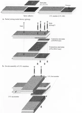
The specimens passed through two main phases during preparation: gluing and assembly (Fig. 1). It is recommended that the gluing (Fig. la) be performed indoors to gain better reliability of the glued joints. The top and foot LVL mem- bers, with the same final thickness appearance of LVL 120E (JAS), were at first composed of two identical elements of LVL 60E (JAS) and were processed and glued with metal plates separately. The metal plates were glued on one side at both extremities of each LVL element, which were then
stored for curing one above another inside the factory at 20~ and a high relative humidity for 1 week (specimens were prepared in Chiba Prefecture, Japan during summer). After curing, the joint zone on which the adhesive trickled was sanded until a flat surface was obtained.
The LVL elements were then fixed together two by two with nails, forming the beams and the columns, the top member and foot members, respectively (Fig. lb). These LVL members were finally assembled together using :the connection steel plates and mechanically fastened with bolts (M20 • r
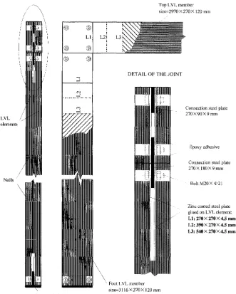
Details of the assembled LVL portal frame are shown in Fig. 2. The frames were separated into three groups LAM 1/2/3, LAM 4/5/6, and LAM 7/8/9, depending on the size of steel plates glued on the LVL elements 270 • 270 • 4.5 mm (L1), 390 • 279 • 4.5mm (L2), and 540 • 270 • 4.5ram (L3), respectively.
Measurements and test procedure
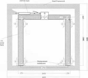
Fourteen transducers were used to measure total displace- ment at the top of the frame (1, 14) and the rotation angles and shear displacements between frame members (8-13) and between columns and steel framework (2-7), as shown in Fig. 3. The actual shear deformation was estimated as the difference between total displacement at the top of the frame and displacement of the foot member, as follows:
no.1 -_no-14 (tad) Y - 2965
where 2965 represents the distance in millimeters between transducers 1 and 14. All the transducers were finally con- nected to an electronic data analyzer that was linked to a computer.
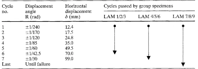
The steel framework was a squareqike steel frame com- posed of two beams and two cross beams. The hydraulic jack actuator {push 20 tons; pull 20 tons; stroke 200mm) was arranged parallel with the top LVL member and freely fixed at the midpoint of the member. A manual hydraulic pump, Riken P-50 type, was used for applying oil pressure to the jack. Loading was controlled by displacement a n d applied twice each toward the positive and negative direc- tions up to the amplitudes of horizontal displacement that correspond to the angles of shear displacement (Table 1).
Table 1. Cycles of loading for the LVL portal frames
Cycle Displacement Horizontal Cycles passed by group specimens
no. angle displacement
R (rad) d (mm) LAM 1/2/3 LAM 4/5/6 LAM 7/8/9
1 _+ 1/240 12.4 i I
2 +-1/170 17.5
3 +-1/120 24.8
4 -+1/85 35.0
5 -+ 1160 49.5
6 + 1/42.5 70.0
7 +-1/30 99.0
Fig. 1. Preparation of test specimens in sequence. See Fig. 2 for explanation of symbols
The cycles passed by each group of specimens were marked in the same table.
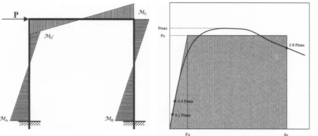
The laterally loaded symmetrical frame of uniform cross section shown in Fig. 4 was chosen as the model of the frames. It was assumed that the connections be- tween b e a m and columns and between the columns and groundsills are perfectly rigid. Furthermore, the shear deformation of the beam and columns and the rigid elements in the panel zone of the joints were neglected. The effect of the eccentric loading at the middle of the top m e m b e r changes the maximum bending m o m e n t M A ( = - - M B ) and M c ( = - M D ) with 1.16% and 1.48%, respectively. Moreover, the eccentric loading had an insignificant effect on the frame's theoretical stiffness. In
the view of these facts, the effect of the eccentric loading was ignored.
Results and discussion
Strength and stiffness of L V L portal frames
Fig. 2. Details of the LVL portal frames
LVL elements
N a i l s
\
\
i
L I L2i L3
i
@ @
2
Top LVL member size=2970 X 270 X t 20 mm
D E T A I L O F T H E J O I N T
Connection stee~ plate 2 7 0 • mm
Base steel plate
\
\ Foot I.VL member size=3116 • 2 1 5 120 mm
Epoxy adhesive
Connection steel plate 2 7 0 • 1 8 0 •
Bolt M20X q)21
Zinc coated steel plate glued on LVL element: L I : 2 7 0 • 2 7 0 • 4.5 r a m ;
L2: 390X 2 7 0 • 4.5 r a m ; L 3 : 5 4 0 • 270 X 4..5 r a m .
Comparison of theoretical stiffness without joint rotation with experimental stiffness
Figure 5 shows the relation between the shear deformation angle of the top L V L member and the lateral force. It can be easily seen that the strength of the structure increased with increasing length of the glued metal plates.
The experimental results of the cyclic loading for all the L V L portal frames are shown in Table 2. The allowable shear force was estimated as three-fourths of the load at 1/120 displacement.
The experimental stiffness line (KR) and the theoretical stiffness line (KT) are plotted in Fig. 5. The experimental stiffness line represents the line that passes through 0.1 Pmax
and 0.4 Pmax of the envelope curve obtained experimentally. This line was compared with the theoretical stiffness line obtained analytically without joint rotation, which repre- sents the ratio between lateral load and maximum displace- ment in the force direction. Values of KR together with KT and (KT/KR) ratio are given in Table 3. The analytical
results were identified by means of comparisons with the experimental results, and they were close enough to demon- strate good stiffness of the frames. Experimental and ana- lytical results agreed closely.
Ultimate load and deformation capacity
Figure 6 shows the definition of the ultimate loa& (Pu) obtained by bilinear approximation using the envelope curves. The ultimate displacement (c5~) corresponding to
0.SPma x was obtained first and then the experimental stiff-
ness line configured, as previously described. Finally, the ultimate load was found so it had the same energy dissipa- tion as the envelope curves up to d u.
Table 2. Experimentai results of the cyclic loading tests
Specimen Size of the glued plates Load at
code (ram) 1/120 tad.
P~20 (kgf)
Max. load in Max. load in Allowable
positive dir. negative dir. shear force
+Pmax --Pmax Qa
(kgf) (kgf) (kgf)
LAM1 } 2280
270 • 270 • 4.5 2160
LAM2 (L1)
LAM3 2200
LAM4 } 1650
390 • 270 • 4.5
LAM5 (L2) 2590
LAM6 2480
LAM7 ] 2600
540 • 270 • 4.5
LAM8 (L3) 2610
LAM9 2700
2670 2250 1710
2560 2190 1620
2700 2220 1650
3100 2710 1238
4190 3770 1943
4080 3230 1860
5670 4590 1950
5590 4710 1958
5570 4850 2025
Fig. 3. Test setup for the LVL portal frames
~U
The ductility factor increased with increasing length of the glued metal plates, showing that the a m o u n t of dissi- pated energy increased with increasing length of the glued metal plates. Better ductility was obtained for the portal frames glued with the longest metal plates (L3); hence their behavior during earthquakes is better than that of the other two portal frames with shorter metal plates.
The structural behavior factor (D~), or load reduction factor, depends entirely on the ductility and type of struc-
ture and represents the resistance reserve capacity of a structure after leaving the elastic behavior. It is estimated f r o m the ductility factor as follows:
1
1
Fig. 4. Frame model and bending moment diagram
Fig. 6. Definition of the ultimate permission)
!oad, (From Yasumura, 6 with
3000
2000
1000
e~0 0 o
-1000
-2000
-3000 -0.05
| 1 7 4
/
-0.03 -0.01 0.01 0.03 0.05
Shear deformation angle (tad)
|
5000- b . I
ooo
i
3 0 0 0 -
2000-
I ...~// 7
G
~ooo-:.
, ,,,~, :
o
ir./,/, [,t,j#.,~/. 4,//'
a '~176176
;!~./,~,:;
.200<
I
4000 -]
-5ooo _i I
-0.05 -0.03 -0.01 0.01 0,03 0.05
Shear deformation angle (tad)
@@
10000 ~ I ~ '
c. ~ -~
3
0
~
-
-
-
4
-
--9_ooo- / i ,~It' ,'2 ~' ;
.4oo0_
-0.05 -0,03 -0.0i 0.01 0.03 0.05 0.07 0.09
Shear deformation angle (rad)
l~ig. 5. Load deformation relation for the LVL portal frames. Metal plate size: a 270 • 270 • 4.5 mm. b 390 • 270 • 4.5 mm. e 540 • 270 • 4.5 mm. KT: theoretical stiffness (thin lines); KR: real stiffness (thick lines). See Table 2 and Fig. 2 for explanation of symbols
Table 3. Real and theoretical stiffness of portal frames
Specimen Size of the glued plates Real stiffness:
code (mm) KR (kg/mm)
Theoretical stiffness: K•K R
KT (kg/mm)
L A M 1 / 124(0.042)" / 1.22
270 • 270 x 4.5
LAM 2 (L1) 106 (0.036) 151 (0.051y 1.42
LAM 3 100 (0.034) 1.51
L A M 4 / 80(0.027)] 1.89
390 • 270 • 4.5
LAM 5 (L2) 130 (0.044) 151 (0.051) 1.16
LAM 6 115 (0.039) 1.31
L A M 7 } 118(0.040) } 1.28
540 x 270 x 4.5 133 (0.045) 151 (0.051) 1.13
LAM 8 (L3)
LAM 9 120 (0.040) 1.26
Table 4. Ultimate load, ductility, and structural behavior factors
Specimen U l t i m a t e Critical Ultimate Ductility Behavior
code l o a d d i s p l a c e m e n t displacement factor factor
Pu d'u d, # Ds
(kg 0 (mm) (mm)
LAM 1 2327 18.8 60.0 3.2 0.4
LAM 2 2279 21.5 47.1 2.2 0.5
LAM 3 2431 24.3 48.9 2.0 0.6
LAM 4 2388 29.9 69.5 2.3 0.5
LAM 5 3644 28.0 97.0 3.5 0.4
LAM 6 3563 31.0 93.2 3.0 0.4
LAM 7 4783 40.5 189.0 4.7 0.3
LAM 8 4804 36.1 175.7 4.9 0.3
LAM 9 4726 39.4 177.4 4.5 0.3
d'u represents the ratio between Pu and KR
sults were obtained for the portal frames glued with the longest (L3), medium (L2), and shortest metal plate (L1), respectively.
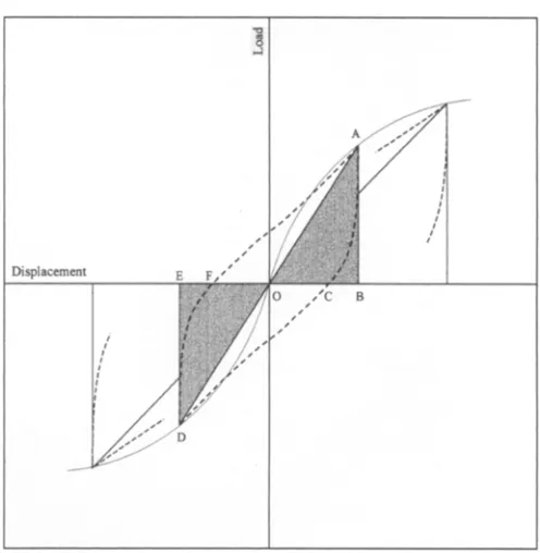
Equivalent viscous damping
One of the dynamic characteristics that describe the energy dissipation capacity of a structure is the equivalent viscous damping, defined in Fig. 7. The equivalent viscous damping represents the dissipated energy (Ea) divided by the maxi-
mum energy stored (Era) , which is the potential energy in
the positive and negative halves of a cycle. These energies can be calculated from the hysteresis loops; E a is the loop area ACDF, and E,~ is the triangle areas O B A and OED. It was estimated with the next formula for each loop:
ed
(3)
hoq - 2Jr •
The equivalent viscous damping results are shown in Fig. 8. Distinct values, varying from 5% to 25%, were obtained for each group of specimens based on their glued metal plate lengths L1, L2, and L3. The equivalent viscous damping for arched frames and frames with moment resist- ing joints, obtained by Yasumura 6 was relatively low ( 2 % - 6%); however, our results could be compared with the results obtained for braced frames (15%-20%) or shear walls (10%-18%) by the same author.
The equivalent viscous damping found was almost con- stant regardless to the shear deformation, proving good energy dissipation of the LVL portal frame. The large deformation allowed indicates good behavior during earthquakes.
Multiplier for the shear walls
In Japan it is common to evaluate the strength of a wooden construction with walls by the multiplier for the shear walls. The frames studied in the present research do not have walls; and at a first glance, it might be difficult to understand the presence of the multiplier for the shear walls. Thinking of the practical purpose of this research - that is, replacing
Fig. 7. Method of obtaining equivalent viscous damping
the missing walls of a structure with wide openings - it was assumed that the multiplier may estimate the strength factor of the L V L frames regarding the lateral strength of the shear walls.
According to the literature, 8 Article 46, Section 3 of the Enforcement Order of Building Standard Law 9 of Japan indicates the multiplier for the shear walls. In conformity with Article 46, l m of shear wall subjected to lateral loading should resist 130kgf load at 1/120 displacement angle and corresponds to a multiplier of 1.
The multiplier for the frames (mframe) w a s expressed by
the admissible strength (Pa) and then divided by the frame span (l = 2.97m) and by the lateral load to which l m of shear wall should resist (130kgf):
P.
mf .... - (4)
50-
~" 40-
3o g 8 > 20-
>
yl0
0 0
i 1
[ ---I! LAId 3 + LAM 5 ~ LAM 7 ~ - -
-/
/,-...
l>"li'J"-~l~
!
0.005 0.01 0.015 0.02 0.025 0.03 0.035 Shear deformation angle (tad)
Fig. 8. Equivalent viscous damping ratio. See Table 2 and Fig. 2 for explanation of symbols
Table 5. Multiplier for the shear wails
Specimen code Admissible load P~ Multiplier for (kgf) shear wall m~. ....
LAM 1 1335 3.5
LAM 2 1280 3.3
LAM 3 1350 3.5
LAM 4 ]238 3.2
LAM 5 1943 5.0
LAM 6 1860 4.8
LAM 7 1950 5.1
LAM 8 1958 5.1
LAM 9 2025 5.2
P, = min(3/4PM20 and 1/2Pm~x)
The admissible load (Pa) was defined by the minimum between load at 1/120 rad (P~20) multiplied by a variability factor of 0.75, and maximum load (Pmax) multiplied by a safety factor of 0.66 and a variability factor of 0.75. The multiplier was calculated separately for plates L1, L2, and L3. The results are shown in Table 5. The multiplier for the shear walls was found to be high, especially for the frames with L3 metal plates.
Failure behavior of L V L portal frames
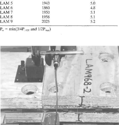
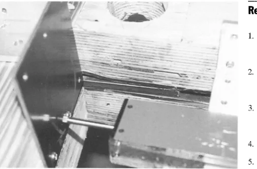
The portal frames failed at an average lateral force of 2600kgf, 3800kgf, and >5500kgf for groups L A M 1/2/3, L A M 4/5/6, and L A M 7/8/9, respectively. Rolling shear was the cause of failure for groups L A M 1/2/3 and L A M 4/5/6. The failure was brittle and occurred between the glued metal plate and LVL, mostly in the L V L and not at the interface (Fig. 9). During loading a number of cracks devel- oped in the L V L parallel to the glued plate at the connec- tion between the frame's top and the foot members as well as between the foot members and the steel framework. They extended until the whole layer near the glued metal plate slipped out. In the case of group L A M 7/8/9, some local buckling of the glued plate L3 was observed near the bolt (Fig. 10). During loading, contact pressure developed between the foot member and the steel framework, and the steel plates glued on the L V L member started to buckle. This group of specimens did not fail because the tests were stopped after completion of the last cycle owing to large displacements. The glued joints had good behavior during tests; moreover, the knife test performed after the experi- ment was finished revealed good adhesion between LVL and the metal plate. Failure in wooden material is com- monly considered a sign of properly chosen adhesive for wood adhesive joints.
In the case of portal frames glued with the longest metal plates (LAM 7/8/9), the mechanical connection created good strength and ultimate displacement, which caused
Fig. 9. Failure mode of portal frames LAMi/2/3 and LAM4/5/6
yielding of the steel plates and consequently dissipation of large amounts of energy. This phenomenon did not happen for the groups glued with shorter metal plates (LAM 1/2/3 and L A M 4/5/6), because they failed before the yielding of the steel plates, It is worth mentioning that the above results were obtained for specimens without reinforcement, whereas in practice the addition of drift pins to the mechani- cal connection with bolts is strongly recommended to avoid the brittle status of the failure.
Conclusions
The results showed that L V L portal frames using glued metal plates at joints behaved well during tests and may be applied to traditional Japanese structures. Four major con- clusions may be drawn from this research:
1. The L V L portal frames with L3 steel plates proved to be ductile and rigid and they allowed a large deformation during cyclic lateral loading. The worse results obtained for medium (L2) and short (L1) plates are due to the rolling shear between the plates and LVL.
Fig. 10. Local buckling of the glued plate L3
3. T h e multiplier for the shear walls was high c o m p a r e d with the prescribed multiplier for frames with walls, to com- p e n s a t e for the missing walls a n d to assume the load carry- ing for the structure.
4. T h e ductility a n d b e h a v i o r factors estimated for the L V L portal frames were high, ensuring that the structures can survive without fatal damage, even if violent earth- quakes occur.
Acknowledgments The authors owe thanks to Keyo Co. and Itochu Kenzai Corporation for the rich exchange of information and their support throughout this research.
References
1. Kataoka Y, Naito K, Ando H (1996) Re-Examination of Japanese traditional wooden frame structures. In: Proceedings of inter- national wood engineering conference, New Orleans, pp 191- 198
2. Miyazawa K, Kohara K (1996) A study of wooden houses due to the 1995 Hyogo-Ken Nambu earthquake. In: Proceedings of international wood engineering conference, New Orleans, pp 339- 346
3. P~rvu C, Yoshida H, Taki K (in press) Development of LVL frame structures using glued metal plates joints. I. Bond quality and joint performance of LVL-metal joints using epoxy resins. J Wood Sci 45:284-290
4. Key Lain, LVL Manufacturing Company (1998) LVL for structural purposes, Brochure with technical data (in Japanese)
5. Sano A, Ptrvu C, Yamada M, Taki K, Yoshida H (1999) Bondability of metal to wood joints. II. Improvement of the water resistance of epoxy resin in metal-wood joints (in Japanese). Mokuzai Gakkaishi 45:244-250
6. Yasumura M (1996) Evaluation of seismic performance of timber structures. In: Proceedings of international wood engineering con- ference, New Orleans, pp 45-52
7. Housing Bureau, The Ministry of Construction (1990) The building standard law of Japan. Notification no. 1792. The Building Center of Japan, Tokyo, Japan
8. Yasumura M (1993) Japan overview: design of timber joints in seismic zones. In: Proceedings of international workshop on wood connectors, Madison, WI, pp 42-51