
1
Research paper
2
Effect of energy balance evaluation on conceptual
3
design of electric and hybrid aircraft
4
J. Rohacs, D. Rohacs
5
Department of Aeronautics, Naval Architecture and Railway Vehicles, Budapest University of Technology
6
and Economics
7
Correspondence: [email protected], +36305819373
8
9
Abstract: Nowadays, all the stakeholders, policy makers, regulators, aircraft designers, producers,
10
operators, etc.) are intensively working on development of the aircraft with full electric and hybrid
11
propulsion systems. However, the technical, technological constrains (like limit on accumulator
12
energy density) require introducing a new approach to conceptual design of such aircraft. The new
13
methods is based on energy and mass balance evaluation. This paper analyses the identified
14
constrains; integrates the energy and mass balance equations into the preliminary definition and
15
calculations of the aircraft performance. By this way, the technological constrains might be
16
transferred into the limitation on the aircraft energy and mass breakdown, that initiates a new
17
approach to aircraft conceptual design uses the knowledge based multidisciplinary optimization.
18
The paper describes the developed methodology for conceptual design of aircraft. It show results of
19
implementing this new development philosophy to conceptual design of a four-seat small
20
electric/hybrid aircraft and a special hybrid cargo UAV. The discussion of the results including got
21
by using the emerging and enabling new technologies and new methods and solutions (including
22
for example distributed propulsion system, unconventional forms, morphing, biomimics, etc.),
23
demonstrates the possible implementation of the new development philosophy, new approach to
24
aircraft conceptual design.
25
Keywords: full electric aircraft, hybrid aircraft, energy and mass balance equations, conceptual
26
design, constraints
27
28
1. Introduction
29
Nowadays the aeronautics faces a non-classical market pull – technology push innovation [1].
30
The market pull appears as society needs in greener, more effective, on demand transport that is
31
supported by visions and actions of the policy makers, regulators (see for instant the [2 – 5]). The
32
same documents try to define the possible directions and areas of the technology developments,
33
technology push. The system is non-classical, because the aeronautics including air transport is in
34
transition from the second “S” curve of its development to the third one. This new ”S” curve might
35
be defined by several emerging technologies and radically new solutions [3 – 5] (like morphing, active
36
flow control, biomimicry, etc.). The basic visions published for millennium or could not predict the
37
introducing the electric aircraft concept (as Vision 2020 [2]) or they put only the electric propulsion,
38
advanced fuel cells, high efficiency electric motors on the list of revolutionary vehicles – technologies
39
as NASA BluerPrint [5]). Later, the IATA Technology Roadmap [6] published at 2013, predicted the
40
entry into the service of the more electric aircraft, namely aircraft with electric systems, before 2020;
41
while the mid-size full electric aircraft might be introduced into the operation after 2035 (if the
42
accumulator power density would be increased considerable about 3 times comparing to the recent
43
technologies [7]).
44
The policy makers, regulators, stakeholders’ teams define too ambitious goals as reduction of
45
90% in NOx-emissions, and 75% in CO2-emissions [3, 4]. Other international, national organizations
46
are on the same positions [8-10]. By using the simple innovative solutions, e.g. improving the existing
47
technologies, solutions (applying more light materials, advanced aerodynamics, increasing engine
48
and propulsion system efficiency, engine – airframe integration, new ATM, rethinking of the
49
operational concepts, ground and flight operations, etc.) that goals cannot be achieved. Therefore, the
50
radically new technologies, original and unconventional solutions are required (developing by using
51
the thinking out of the box principle [11 - 13]).
52
Probably, the most powerful solution enabling to achieve the targeted emission reduction is the
53
development of the new aircraft with electric or hybrid propulsion systems.
54
It seems the electric aircraft concept is not so new. According to the list of electric aircraft
55
published by Wikipedia [14], the first electrically driven flying machine was a dirigible “La France”,
56
constructed by Charles Renard, Arthur Constantin Krebs and Hervé Mangon and flown in 1883 – 84.
57
The second electric aircraft was the PKZ-1 rotorcraft developed by Petróczy, Kármán and Žurovec
58
for replacing the dangerous hydrogen filled observation balloons. The rotorcraft built in Hungary in
59
1917 under control of the young von Kármán had 3.9 m four-blades rotor driven by an Austrian –
60
Daimler electric motor generating 140 KW (190 hp) power and supported by the ground based
61
generator fed direct current through tethering cables.
62
Because the low power/weight ratio, the electric aircraft could not find their real
63
implementation. At 1943, the Lockheed developing the bomber L-249 (got XB-30 code in army)
64
studied the use of electric power assisted control, but it was found the hydraulic systems are
65
considerable efficient [15]. The next large step was done by developing and implementing a 63 kW
66
electric fuel pump and controller for F-16 [15]. Finally after revolutionized power electronic weight
67
since 1992 the electronically based hardware became enabling to use in aircraft.
68
Nowadays, all the stakeholders policy makers, regulators, aircraft designers, producers,
69
operators, etc.) are intensively working on development of the aircraft with full electric and hybrid
70
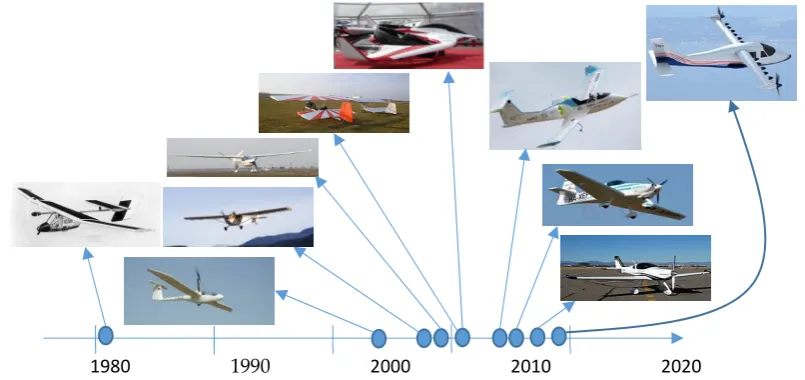
propulsion systems. Figure 1. shows a series of electric aircraft according to their first flight. This
71
figure demonstrates that, the first airplanes were developed as modification of the existing airplanes
72
or developing aircraft of conventional forms.
73
74
Figure 1. Some electric aircraft [16]: 1.- Solar Challenger, 1981 (first flight); 2.- Air Energy AE-1 Silent
75
(ultralight sailplane with retractable electric motor), 2005; 3.- French BL1E Electra F-PMDJ (the first
76
registered electric aircraft in the world), 2007; 4.- Yuneec International E430, China, 2009; 5.- APEV
77
Pouchelec, 2011; 6.- AugustaWestland (Leonardo) Project Zero, 2011; 7.- Airbus E-Fan, 2014; 8.-
78
Magnus –Siemens eFusion, 2016; 9.- By Aerospace Sun Flyer 2, 2018; 10.- NASA X-57 Maxwell, (18
79
distributed engines)
80
The recent and further developments of electric / hybrid aircraft face with series serious
81
problems, technological barriers like low specific energy, thermal instability of batteries. The specific
82
energy of accumulator packs, energy per mass (kWh/kg), equals to 340 – 360 Wh/kg as best. In real
83
applications, the specific energy (SE) of accumulators is about 250 Wh/kg. (So, using 300 Wh/kg is a
84
good approximation.) That means accumulators weighting about 12.4 kg (see 2.1.) may store energy
85
equals to 1 kg kerosene in aircraft usage. Sophisticated cooling system and thermal management
86
must be developed for managing the thermal instability of the battery banks. These are serious
87
barriers in developing the full electric (and hybrid) aircraft. Therefore, there are three possible ways
88
for developing the full electric aircraft. (i) The developers may wait for appearing radically new
89
energy storage technologies, which is not a good option. (ii) Using the traditional, conventional
90
developing philosophies and design methods that result to aircraft with considerable reduced
91
performance, especially 5 – 8 times less range (in case of the analogical other performance). (iii)
92
Creating a new approach to the preliminary and conceptual design of the aircraft.
93
This paper follows the third option. The new methods may base on energy and mass balance
94
analysis. This paper analyses the identified constrains and recommends to use the aircraft mass and
95
energy equations for understanding the problems and barriers balking and delaying the developing
96
the full electric aircraft and their quicker introducing into the operation. It describes a series of new,
97
even radically new ideas how to improve the performances of the electric and hybrid aircraft. It
98
integrates the energy and mass balance equations into the preliminary definition and calculations of
99
the aircraft performance. By this way, the technological constrains might be transferred into the
100
limitation on the aircraft energy and mass breakdown, that initiates a new approach to aircraft
101
conceptual design. The paper shows results of implementing this new development philosophy to
102
conceptual design of a four-seat small aircraft and a special cargo UAV. The discussion of the results
103
got by using the emerging and enabling new technologies and new methods and solutions (including
104
for example distributed propulsion system, unconventional forms, morphing, biomimics, etc.)
105
demonstrates the possible implementation of the new development philosophy, new approach to
106
aircraft conceptual design.
107
2. Preliminary considerations
108
2.1. Required energy and engine power
109
In first and very draft order, the aircraft required energy support can be defined as choosing the
110
engine type, its sizing and determining the required energy, fuel, for mission.
111
The demand using as input in new aircraft developments defines the engine types. For example,
112
the Pplane and Esposa projects [17 - 19] demonstrated, the total-life cycle cost related to the one flying
113
hours, safety and security risks, demand in availability and door-to-door performances determine
114
the major performance and engine types (Figure 2.).
115
116
Figure 2. Relationship between the door – to – door speed and aircraft categories of the small
117
conventional aircraft
118
0 50 100 150 200 250 300 350 400 450
0 500 1000 1500 2000 2500
Door
to
-d
oor speed (km/h)
Door - to - door distance (km)
tu
rboprops
helic
opter
s
fix
w
ing +
The time, 𝜏 , of availability of air taxi service (minutes from requires until service availability)
119
might be approximated as 𝜏 = 15 + 0.02𝑅, where R is the travelling distance in km. The
120
approximation formulas 𝑉 = (2.1 + 0.0004𝑅) , , 𝜏 = 𝑅/𝑉 define the door-to-door speed
121
(𝑉 in km/h) and time (𝑇 in h) for small aircraft.
122
The operational concept describes using the developing product or service from the user point
123
of view. The flight mission origins from the market needs and it is an important part of the operational
124
concept. It contains realization of the full flight including the flight modes: taxiing, take-off, take-off
125
flight path, climb, cruise / en route flight, descent / gliding, loiter, landing approach, landing (and
126
taxiing). The energy must be determined for such mission, in which the altitude and the speed of
127
cruise flight (as level flight with constant velocity) are the most important variables (for commercial
128
aircraft). The total energy (fuel) required includes the energy needed for solving the flight mission
129
and additional a half hour flight as reserve.
130
The aircraft design process is a multidisciplinary nonlinear optimization process with large
131
series of constraints [20, 21 (Part I., and II.), 22]. There are several types of constraints as legal,
132
economic, technological, mechanical, aerodynamic, flight performance, flight mission, flight
133
dynamics, stability, control, etc. The legal constraints are defined by the airworthiness requirements
134
as mechanical (stress, weight) constraints or as flight performance, stability and control criteria. ). For
135
example, as it identified [23, 24], the very light airplanes (with take-off mass less than 750 kg and
136
stalling speed less than 83 km/h) ) should have take-off distance (horizontal part of flight path from
137
start up to reaching the 11 m above the take-off surface) less than 500 m [25]. According to the
138
Certification Specification, CS 23 [26] the normal, utility and aerobatic category reciprocating
engine-139
powered aeroplane of 2 722 kg or less maximum weight must have a steady gradient of climb at sea
140
level of at least 8.3% for landplanes and 6.7% for seaplanes and amphibians with retracted landing
141
gears and flaps in take-off position. The analogical aeroplanes with gas turbines and extended
142
landing gear should have 4 % steady gradient of climb after take-off.
143
In any case, the regulations as usually follow only the technological changes. Now, there is a
144
time for creating the certification specifications for full electric, hybrid and highly automated aircraft
145
including the unmanned and autonomous versions, too. The regulation must cover the testing and
146
certification of the new technologies like batteries thermal instability or load test of operating gas
147
turbine – electric energy generation units rotating with more than 100 000 rpm.
148
By the way, the two seats plane Pipistrel Alpha Electro is the first all-electric trainer aircraft
149
getting the FAA airworthiness certification [27] that validates, the new technologies might be certified
150
within the existing system of airworthiness and requirements.
151
Future greener aviation should use the electric or (because the technology barriers – see next
152
sub-chapter) hybrid propulsion systems. The governing characteristics is the hybridization factor
153
defined by Appendix I. that gives information about the charging, discharging characteristics of
154
batteries, too.
155
The conceptual design intents to develop the aircraft in conceptual form. It has three major steps
156
[20]. (i) The first guess sizing based on analysis of future needs, requirements, available and emerging
157
technologies and on the “sketches”. (ii) The second step is an iteration process of sizing and
158
performance optimisation developing the initial layout. The process is based on analysis and
159
optimisation of aerodynamics, weighting (weight balances), propulsion and flight performance. (iii)
160
Finally, the third step of the conceptual design deals with second iteration with goal of refined sizing
161
and optimisation including the structure, cost, etc.
162
A citation from know basic book on conceptual design [20] published by Daniel Raymer:
163
“Sometimes a design will begin as an innovative idea rather than as a response to a given
164
requirements.” may underline the role of conceptual design in developing the future, unconventional
165
aircraft.
166
The well-known and applied methods of the aircraft conventional conceptual design [20, 21 (Part
167
I., and II.), 22] have been adapted to electric and hybrid aircraft design by several researchers,
168
improvements: (i) reformulation of the operation concept and mission, (ii) correcting the weight/mass
170
formulas and (iii) improving the aircraft performance (range) determining methods.
171
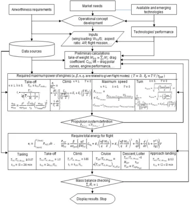
Figure 3. depicts the improved conceptual design methodology. The operational concept
172
derived from market needs, available and emerging technologies and qualified by the airworthiness
173
requirements. All these provide inputs for the conceptual design.
174
The preliminary calculation uses the available data on the existing solutions, constructions,
175
aerodynamic, etc. characteristics of analogical aircraft and theoretical and semi practical methods and
176
provides the aerodynamics coefficient, preliminary defined mass balance and relative masses
177
(weights), etc. supporting the future studies. Principally, this is the initial guess sizing.
178
There are two major cycles embedded. First deals with calculation of the required (maximum)
179
power. The second determines the total required energy for supporting the full flight mission. The
180
objectives of these actions are the synthesis the full aircraft in optimal form depending on the
181
constraints. This is the second step of the conventional conceptual design process.
182
183
Figure 3. The conventional conceptual design methodology adapted to developing the electric and
184
hybrid aircraft
185
The design process might be stop, if the mass balance checking demonstrates the acceptable and
186
realizable results. Of course the aerodynamics, flight performance, stability and control, etc.
187
performance optimisation including for example the structural solutions, life-cycle cost and
189
environmental impact minimisation, etc. may really finish the conceptual design process.
190
Figure 3. summarizes the methods of calculation the required maximum power and mission
191
total energy for different flight phases. The Appendix II. and III. define the applicable formulas based
192
on the theoretical and semi practical methods.
193
The Appendix IV. shortly describes the weight and energy balances equations that are very
194
important parts of methodology, too. Chapter 3 describes their role in developing methodology and
195
the ne methodology.
196
2.2. Possible energy support
197
There are several methods may improve and greening the future aviation starting from
198
considerable drag reduction (like laminar wings, laminar aircraft, active flow control by use of MEMS
199
(Micro-Electro-Mechanical Systems) technologies) up to introducing new energy generation methods
200
(as fuel cells) and alternative “fuels” including electric energy as fuel, too.
201
This paper focuses its activity on the electric / hybrid propulsion systems, and their
202
implementation only. This means, the paper deals with full electric propulsion system and with
203
hybrid propulsion aircraft using the full electric modes in all flight and movements under 500 m of
204
flight height (for small aircraft) and under 1000 m (for larger aircraft). Therefore, the applied methods
205
of electric energy generation (as fuel cell, electric generators driven by internal combustion engines /
206
gas turbines, or integrated photovoltaic elements into aircraft surface / structure) are less important
207
in this study.
208
Figure 4. comparing the characteristics of the electric batteries to gasoline (jet fuel) [34 – 36], calls
209
up attention on a very serious problem, small specific energy of the available accumulator
210
technologies. It is a very important barrier delaying the electric / hybrid aircraft developments.
211
212
Figure 4. Energetic comparison of the applicable fuels
213
This figure may explain several interesting problems. At first, the specific energy of kerosene
214
about 30 – 40 times greater than the specific energy of the available batteries. By taking into account
215
the total efficiency of the propulsion systems (equal to about 24 – 28 % in case of conventional and
216
around 76 – 82 % in case of full electric systems including the propellers’ efficiency, too), a kg of
217
kerosene contains usable (useful) energy that might be stored by 12 – 13 kg batteries. That means the
218
The law specific energy of the battery technologies does not allow to make a full electric aircraft
220
without considerable reduction in their performances. The mass of full electric aircraft increases for
221
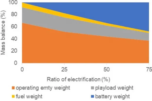
40 - 400 % depending on the accepted radical reduction in range. Figure 5. demonstrates, the changes
222
in relative mass balance of the he possible small size (around 50-seat) regional hybrid aircraft [28]
223
equipped by electric butteries with 500 Wh/kg specific energy (that unit is about 60 – 70 % greater
224
than specific energy of the today available batteries). Commercial load relative mass of such aircraft
225
will be less for 48 %, (cutting down from value 25,8 % to 13,1 %) in case electrification factor equals
226
to 75 %. At the same time, the take-off gross mass increases for 96 %, the required wing area for 134
227
%. So, such large electrification today is not realizable; the cost of transporting the goods, people may
228
double and more.
229
230
Figure 5. Weight balance of the middle size regional hybrid aircraft depending on electrification
231
(drawn by use of results published by Antcliff et al. [28]
232
People may staying in position, this technological barrier (low specific energy) is not so hard
233
problem, because the sciences and technologies are developing very actively in accelerated form and
234
the diffusion time of new products into the market considerable and continuously reduces. At first,
235
as it can be seen in Figure 4., the specific energies of the available lithium-ion, lithium-polymer
236
accumulators are close to their technical limits. The future, emerging technologies allow to develop
237
the aluminium-air, lithium-air accumulators, which may have already the acceptable specific energy
238
density. At second, the accumulator technology developments are not follow the Moore’s law [37],
239
according to which the transistors on a chip doubles every year while the costs are halved. So, the
240
availability of the required emerging accumulator technologies at 2030 – 2035 might be too optimistic
241
expectation. Plus to it, the emerging accumulator technology may reach the theoretical limits of the
242
known battery technologies. For success absolutely new energy storage technology should be
243
developed.
244
Another important problem is generating by a false hope: the electric aircraft have zero emission.
245
The media, green organisations, foundations and generally the societies accept, diffuse and
246
propagandize this incorrect information as a “governing” principle. They are forgetting about the
247
emissions of electric energy generation, accumulator and generally the aircraft production, building
248
the required infrastructure, etc.
249
By taking into account all these effects and determining the total environmental impacts, the
250
picture is not so nice [38, 39]. At first the electric energy generation causes large impact on the
251
environment (Figure 6.) depending on the mix of energy generation [40]. At second, the total life cycle
252
emission of existing and electric /hybrid aircraft are not so different. According to the Figure 7. the
253
full electric aircraft may have less total environmental impact in case when the performance,
254
especially the range of aircraft really cut down. The hybrid aircraft with light hybridization factor
255
(equals to 10 – 25 %) may reduce the environmental impact in airport regions and generally the total
256
258
Figure 6. Greenhouse gas effect of electric energy generation in several selected countries (drawn by
259
use of data published by [40] (and given in CO2 equivalent form)
260
261
Figure 7. The total life cycle CO2e emission of the investigated aircraft given in g/pkm form
262
(hypothetical conventional aircraft analogical to Cessna 172, electric aircraft with buttery banks 600,
263
400, 200 KWh, hybrid aircraft applying only electric power for 45 or 15 minutes during its flight)
264
3. New approach to aircraft conceptual design
265
3.1. Aircraft mass and energy balance equations
266
The conventional conceptual design methodology adapted to developing the electric / hybrid
267
aircraft (Figure 3.) applies the mass and energy balances for evaluating the concept and possible
268
realization of the new aircraft. Here weight balance is used not as simple balance defining the aircraft
269
centre of gravity. This is an equation describing the sum mass (weight) fractions.
270
Raymer [20] defined the aircraft take-off mass in very simplified form:
271
𝑀 = 𝑀 + 𝑀 + 𝑀 + 𝑀 . (1)
By introducing the mass fractions (relative masses) for fuel and empty mass
272
𝑀 = 𝑀 + 𝑀 + 𝑀 + 𝑀 𝑀 , (2)
0 200 400 600 800 1000 1200 1400 1600 1800 2000
EU 28 France Germany Hungary Lithuania Poland Sweden USA Brasil China India
electric energy generation (CO
2e - g/KWh)
0 100 200 300
conventional hybrid 15 hybrid 45 electric 200 electric 400 electric 600
the formula
273
𝑀 = 𝑀 + 𝑀
1 −𝑀 −𝑀 𝑀𝑀
(3)
can be used for determining the take-off mass with use of estimated fuel and empty mass. This is
274
often called as weight budget formula that uses the weight breakdown defined by (1).
275
The equation (1) can be given in more generalized form:
276
𝑀 = 𝑀 + 𝑀 + 𝑀 + 𝑀 + 𝑀 + 𝑀 + ⋯ = 𝑀 ∑ 𝑀 . (4)
Because the mass fractions (relative masses) might be defined as function of the available
277
technological and production levels (see Appendix IV.) this equation might be called as mass balance
278
equation. In more general form, this equation represents the possible realization existence of aircraft.
279
So, it is the aircraft existence (or life) equation. If the ∑ 𝑀 > 1, than the aircraft with predefined
280
performance can not be built in the given production environment (in given country) with planned
281
performances. The ∑ 𝑀 < 1 condition shows that even better aircraft with better performance
282
might be built. Finally, the ∑ 𝑀 = 1 means the best aircraft is built.
283
There are many general [20, 21 (Part I., and II.), 22, 41 - 43 ] and specialized [44, 45] books deal
284
with defining, description and estimated semi practical formulas of the aircraft parts including for
285
example mass of wings or fuselages depending on their real structural solutions and load conditions,
286
load management.
287
These practical formulas are widely used in aircraft conceptual and preliminary design.
288
The energy balance is an analogical equation estimating the total energy required for realization
289
the aircraft flight mission (sum of energy consumptions for the mission legs - see Appendix IV.):
290
𝑒 = 𝑒 + 𝑒 + 𝑒 + 𝑒 + 𝑒 + 𝑒 + 𝑒 = 𝑒 ∑ 𝑒̅ . (5)
This equation can be applied for optimization of the energy consumption, energy management.
291
3.2. New conceptual design methodology for developing the electric / hybrid aircraft
292
The conventional conceptual design methodology (Figure 3) had been applied to developing
293
five types of 4-seat small aircraft with different propulsion systems [19, 23, 24]. The aircraft
294
performance were compared with a hypothetical conventional aircraft analogical to Cessna 172N
295
with range 1300 km and cruise speed 226 km/h. The draft names (aircraft 200, aircraft 400, …, hybrid
296
15, …) of developing aircraft “explain” the major characteristics of the propulsion systems. The
297
batteries of developing aircraft may storage the 200, 400 and 600 KWh. In cases of using the hybrid
298
propulsion system, the aircraft are able to fly 15 or 45 minutes in full electric modes.
299
Figure 8. shows the radical increases in total masses and required mass of the battery banks. The
300
conventional and hybrid 15, hybrid 45 aircraft have the same range 1300 km. The electric aircraft with
301
200, 400 and 600 kWh battery capacity have ranges 360, 520 and 640 km, only.
302
Figure 9. underlines another important problems associated by mass balance (and energy)
303
balance. As it can be seen in figure, the relative mass of propulsion system (including the engines or
304
electric motors, propellers, system elements like axis, wires, cooling system and batteries masses)
305
increases up to 65 %; while the relative mass of commercial load (payload) reduces from 36 to 10 %.
306
These results rather similar with result got in conceptual design of larger (50-seaters) aircraft (see
307
Figure 5.).
308
This changes in mass breakdown generated new idea: the future electric / hybrid aircraft should
309
be developed by introducing a series of preliminary defined extra constraints on the mass and energy
310
balances. Of course another constraints (for example on total life cycle cost) might be defined, too.
311
Generally, by developing the technology for electric / hybrid aircraft the design space increases
312
dramatically [46] that requires radically new solutions like synergetic, tightly-coupled morphological
313
and systems integration emphasizing propulsion – as exemplified by the potential afforded by
314
introduced by electric flight concept [19, 23, 24, 28, 33, 50] leads to rethinking the conventional
316
conceptual design methodologies of aircraft.
317
318
Figure 8. The mass breakdown (kg) of the a series of conceptually designed aircraft analysed aircraft
319
320
Figure 9. The mass balance (mass fractions) of the conceptually designed aircraft.
321
The developed and proposed new approach to aircraft conceptual design methodology has the
322
following important novelties:
323
• adaptation of the conventional conceptual design methodology to electric / hybrid aircraft
324
developments based on iteration on required maximum power and energy required for
325
realization the predefined flight mission,
326
• introducing new, predefined constraints for mass and energy balances (mass and energy
327
fractions),
328
• generating original new solutions by applying the thinking out of the box concepts.
329
The adapted methodology uses four types of inputs (see Appendix I. and II.):
330
• performance derived from developing operational concept (as number of seats, nse, range, R,
331
cruise speed, VCR maximized take-off distance, sTO,, etc.) and airworthiness requirements (as
take-332
off distance, sTO, or rate of climb, ℎ , load factor, n);
333
• predefined constrains (legal, economic, etc.) requirements including the extra constraints on
334
mass and energy balances;
335
• technical, technological characteristics of the propulsion system (like hybridization factor, HF,
336
battery discharge and recharge rates, C-rates, efficiency of elements of the propulsion systems,
337
0 0.2 0.4 0.6 0.8 1 1.2
conventional hibrid 15 hibrid 45 electric 200 electric 400 electric 600
battery specific energy, SEb, engine specific energy (or / and power-to-weight ratio) of the
338
conventional engines (ICE, GT, TP), SEce;
339
• aerodynamic data and flight performance (as polar curve diagrams, CL = f(CD), wing aspect ratio,
340
AR, wing loading, wL = WTO / S).
341
Using extra constraints on mass and energy balances calls for developing very special aircraft,
342
operating by applying radically new solutions. For example, the mass of airframe can be reduced by
343
deployment of the new materials, lightweight flexible airframe, like wing (of course with gust effect
344
elimination and life management), morphing, structural solutions based on biological analogies
345
(biomimicry), etc.
346
Some constraints introduce accepted changes in performances. For example accepting reduction
347
in flight performance, less cruise speed, longer take-off distance, etc. may lessening the mass of
348
required batteries.
349
The radically new, original solutions may implement the ideas introduced by projects
350
developing the “out of the box thinking” solutions [11 – 13, 51 - 52], including take-off by ground
351
energy support (Figure. 10.), aerial refuelling or cruiser – feeder concept. Recently, most of
352
revolutionary new ideas as ground support by energy the aircraft during take-off or replacing the
353
battery packs during cruise flight would seem too radical, unrealizable solutions, while delays in
354
their implementation caused by problems of society, stakeholders acceptances rather than technical
355
unsolved problems.
356
357
Figure 10. Take-off and landing assisted by magnetic levitation system supported from ground
358
The developers may define new constraints partly subjectively.
359
4. Applicability of the new conceptual design methodology
360
4.1. Conceptual design of a 4-seats aircraft
361
The professional task of IDEA-E project [50] was defined as to analyse and develop the electric
362
and hybrid aircraft. According to the market analysis, there were identified needs in 4 –seaters small
363
aircraft and cargo UAV.
364
The latest results of sciences and technologies allow emerging a safety, environmental friendly
365
and economic new Personal Air Transportation System (PATS) [54 – 55].
366
There are many projects developing the future small aircraft and small air transportation
367
systems. EPATS - European Personal Air Transportation Systems [56, 57], PPlane - Personal Plane
368
[58, 59], SAT-Rdmp Small Aircraft Transport – Roadmap [60], or Esposa – Efficient Systems and
369
Propulsion for Small Aircraft [61] are the EU supported projects. Others, as NASA SATS - Small
370
Aircraft Transportation System [62, 63] or IDEA-E [50] are the national projects.
371
All these projects have developed new small aircraft, small engines, new technologies and
372
solutions that open new business sector in air transport system. This new business supports the
373
personal air transport including even daily use of aircraft. This new system required new small
374
Finally, the projects resulted to definition the personal aircraft that may have up to 9 seats and limited
376
range (about 800 km) and limited flight time (less than 3 hours). This performance may allow to use
377
the electric or hybrid propulsion system.
378
The objectives of a national project IDEA-E [50] includes development of a 4 seats hybrid aircraft.
379
The project team has made large work and has published the first results already according to
380
investigation of elements of the propulsion systems (as batteries [36], hydrogen cells [64] and
381
developing aircraft [19, 23, 24] (see Figures 8. and 9., too).
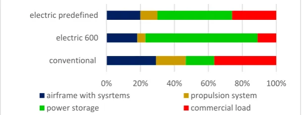
382
Figure 11. proves an example of mass balance of an electric aircraft developed by using the
383
predefined additional constraints (as limitation on the relative mass of airframe) comparing with
384
conventional and electric 600 aircraft. As it can be seen, the electric predefined aircraft has relative
385
mass of power storage system (batteries) considerable smaller than the electric aircraft 600 (designed
386
by using the conventional conceptual methodology) but – of course – much more greater than the
387
mass of fuel used by conventional aircraft.
388
389
Figure 11. Effect of limitations on the mass balance (conventional, electric 600 and future electric
390
aircraft)
391
The available technologies (as new composite materials, new lighter engines, etc.) are ready to
392
support the small electric / hybrid aircraft developments. Two factors, reducing the empty mass
393
fraction for 20 – 25 % and range for about 30 – 60 % comparing to the existing aircraft (most of them
394
were developed 20 – 60 years ago, and give rooms for considerable improving the structure and
395
efficiency) may results to required performance. The range of small 4-seaters aircraft might be defined
396
by the modified Breguet range equation (see Appendix V.):
397
𝑅 =
( ) 𝑘 ( ) ln
( )
. (6)
Figure 12. defines the change distribution in range of 4 seaters small aircraft (analogical to the
398
Cessna 172) depending the hybridization (energy split) factor, ψ, and the cruise speed, M [65].
399
400
0% 20% 40% 60% 80% 100%
conventional electric 600 electric predefined
airframe with sysrtems propulsion system
power storage commercial load
Range
[km
Figure 12. Range depending on hybridization factor and cruise speed
401
As it can be seen, the best solutions are the hybrid aircraft with light hybridization.
402
The introduced conceptual design method applying to 4 seaters hybrid aircraft design (in case
403
of using the weight estimation functions provided by Torenbeek [22] and limiting the range as 400
404
km) results to stable take-off mass after 8 – 10 iteration already [66].
405
4.2. Conceptual design of a cargo UAV aircraft
406
This sub-chapter describes and shortly discusses the first results of the conceptual design of
407
family of cargo UAVs with electric / hybrid propulsion systems [24, 64, 67, 68].
408
The large cargo UAV developments, as PUKA [69] and small drones’ application for goods
409
delivery [70] in cities are well known. However, there are a lack in developing the moderate cargo
410
UAVs. For instant, Boeing develops a special cargo air vehicle as electric vertical take-off and landing
411
(eVTOL) aircraft for transporting goods of weight 339 kg (Fig. 9.). As it might be recognized this cargo
412
UAV has rather unconventional form. This is a way, how the effective UAV might be built.
413
414
Figure 13. The Boeing HorizonX is an unconventional eVTOL cargo air vehicle [71]
415
The preliminary market analysis identified needs in cargo UAV carrying 1 – 10 hundreds of kg
416
payload for distance 100 – 300 km. This wide range in required performance calls for developing a
417
series of aircraft. There are three different sizes, but analogical aircraft under development. Each
418
aircraft may adopt to transfer 1 – 3 containers. The smallest may hold containers of 50 kg mass, that
419
is to say, the aircraft commercial load might be 50, 100 or 150 kg. It has a range 100 km. The larger
420
airplane may carry containers of 200, 300 or 400 kg mass for distance 200 km. While the larges can
421
transport goods of 600, 800 or 1000 kg for up to 400 km [24].
422
The flight mission is defined very simple: taxiing, take-off, climb, cruise, descent, approach and
423
landing. The cruise modes, (velocity and altitude) are optimized for block time, and actual
424
commercial load. The block time (time from starting the take-off until stopping the aircraft after
425
landing) is defined as 1 hour 30 minutes, 2 hours and 2 hours 30 minutes for the 3 different size of
426
aircraft with full loads. Because the highly adaptive wings the users may operate, the aircraft flying
427
on smaller cruise speed (that increases the block time). The defined take-off distances are 60, 100 and
428
200 m. Rate of climb is defined as minimum 3 m/sec
429
It seems the largest aircraft carrying 600 – 1000 kg loads rather similar with small 6 – 9 seats
430
aircraft. On the other hand, developing the smallest version faces critical problems. At least the
431
known smallest aircraft like Cri-Cri (Fig. 10.) or SD-1 have relative empty mass (empty mass per
take-432
off mass) equals to 0.45 or higher. (By the way, on 9 July 2015 an electric version of Cri-Cri, built by
433
435
Figure 14. Cri-Cri, the World smallest twin engine manned aircraft designed by French Colomban
436
(https://en.wikipedia.org/wiki/Colomban_Cri-cri)
437
The IDEA-E [50] team defined to start the developing process with the smallest cargo UAV in
438
its maximized form carrying 150 kg payload for distance 100 km during 90 minutes. For reaching the
439
objectives a series of extra constraints were defined [24]:
440
• the structural mass (as relative empty mass without the elements of the propulsion system)
441
must not go over 0.2;
442
• the relative mass of batteries should be less than 10 %;
443
• the commercial load should be greater than 40 %;
444
• under 500 m height of flight, the aircraft must use full electric modes;
445
• the electrification factor must be below 0.2; and
446
• the power of the aircraft must be enough for recharging, the batteries fully during the cruise
447
flight.
448
The developed aircraft has the following geometrical characteristics (for case of carrying the 150
449
kg cargo): length: 4.7 m; wingspan: 7.6 m; wing area: 9.4 m2; take-off mass: 350 kg, take-off distance:
450
60 m.
451
The developing aircraft must have really unconventional form for guarantee the required
452
efficiency and performance.
453
It seems the airfoil selection / design and determination of the wing / aircraft aerodynamic
454
characteristics are the central problems of developing this new, unconventional airplane. The
455
modified (in thickness, camber, positions of maximum thickness and camber) and combination of
456
two different airfoils and specially developing airfoils were studied. The applied solution requires
457
further aerodynamic investigation and development.
458
The applied unconventional form results to considerable reduced empty weigh of airplanes, but
459
the parasite drag (drag at zero lift) is about 30 – 40 % greater, than the aircraft with analogical weight
460
/ size. Therefore, the cruise speed should be reduced and kept moderate.
461
The hybrid propulsion system are selected because the technological barriers delaying the full
462
electric aircraft developments. The system is based on a small size gas turbine driving an electric
463
generator. This engine – generator is mounted in central part of the fuselage. Air inlet is at the upper
464
side of the noise (Fig. 15.). The inlet is at upper side too, or at the both lower side of fuselage after gas
465
turbine and commercial load packages. 4 – 8 electrically driven propellers having own small electric
466
motors equip the aircraft. The propellers and their motors are integrated into the wing and they
467
“work” on full span.
468
There is not conventional fuselage and cockpit. The airframe is built from the minimum
469
elements: fuselage as beam truss box with gas turbine – electric energy generator and batteries inside,
470
wings of variable geometry and tail (Fig. 15.)
471
The control unit is mounted into the “head” of aircraft that is streamlined small body made as
472
474
Figure 15. Layout of developing small cargo UAV with hybrid propulsion system (1.- fuselage, 2.-
475
engine inlet, 3.- control box, 4.- batteries, 5.- gas turbine with electric generator, 6.- propellers, 7.- fix
476
wing, 8.- flexible part of wing, 9.- exhaust gas inlet, 10.- containers, 11.- covering linen)
477
The carrying containers are fixed to the fuselage beam and they are cover by linen strained by
478
shape-retaining frames.
479
The wing has two different sections. The central “rigid” body section holding the propellers
480
driven by individual electric motors (Fig. 16.). The mean beam is a tube. The fixed wing holds
481
batteries, too.
482
483
Figure 16. Wing principal structure (1.- propellers, 2.- electric motors, 3.- hard (composite) wing
484
section, 4.- batteries, 5.- beam – tube, 6.- rod rolling the linen, 7.- flexible (composite), deflectable tip
485
rod, 8.- flexible part of wing (linen))
486
The variable part of wing is a simple, curved linen. It is partly reeled up on a tube at middle
487
section of wing. The trailing edge is a cable in the linen. This cable is stretched between flexible (and
488
deflectable) tip rod and an electric motor built into the fuselage. This motor controls the stretching
489
and position of cable. The motor may move back and down for increasing the wing area and the
490
generating extra lift. This is the flap function. The tip rod can be turned, too, down and up for using
491
the wing tip areas as ailerons.
492
The conceptual design methodology (Fig. 5.) results to the following major mass and energy
493
balances (Tables 1. and 2.) [24].
494
The results demonstrate the special, unconventional cargo UAV might be configured and
495
realized.
496
The project has not finished yet. At first, further investigation is planned for developing and
497
CFD study the airfoil and airplane aerodynamics, improving the structural realisation of the created
498
original solutions and their testing by using the FEM analyses, further investigation and analyies of
499
the stability and new control solutions, and developing the gas-turbine- electric energy generator
500
Table 1. Mass balance of developed UAV
502
503
Table 2. Energy balance of developed UAV
504
505
5. Discussions
506
The future cleaner air transport needs accelerated implementation of the new available and
507
emerging technologies. The most promising new solutions might be realized by developing the
508
aircraft with full electric and hybrid propulsion systems. The total life cycle cost and environmental
509
impact might be reduced for 12 – 27 % depending on the size and flight performance of the aircraft.
510
Using the full electric mode at under 1000 m of flight height may eliminate the chemical emissions in
511
airport regions. Very intensive and active research, development and innovation processes have
512
started for developing the full electric and hybrid aircraft. It is expected to introduce the first full
513
electric and hybrid passenger aircraft (with 50 – 100 seats) into operation around 2035.
514
There is an interesting occurrence has appeared: the scientist, aircraft developer makes their
515
calculation with battery performance 2 – 3 times better than the existing, available best accumulators
516
have. Unfortunately, the available and emerging batteries’ technology (because their small specific
517
energy) may not support developing such new aircraft without radical improvements in battery
518
technologies, introducing new energy storing technologies or considerable reductions in aircraft
519
flight performance.
520
This paper identified the most serious problems and barriers generate delays in full electric and
521
hybrid aircraft development.
522
It seems all the problems are induced by low specific energy (kWh/kg) of the batteries packs
523
(Fig. 4.). It means, one kg kerosene support the conventional aircraft by effective used energy that can
524
The Figure 8. shows, the full electric aircraft (even the small 4-seaters) aircraft can not be realized
526
by using the existing battery technologies. The aircraft mass increases for 3.6 times while the range
527
of aircraft reduces for 50 – 52 %. In case of developing a middle size (50 seats) regional aircraft and
528
using the electric energy in 75 % of required total flight mission energy (75 % of hybridization factor),
529
the take-off gross mass increases for 96 %, the required wing area for 134 % (Fig. 5). At the same time,
530
the payload factor (commercial load mass fraction) will be less for 48 %, (cutting down from value
531
25,8 % to 13,1 %).
532
These large changes in performance are caused not only by large mass of required battery packs,
533
but with fact, this mass must be carried during all the flight. Therefore, the conventionally applied
534
Breguet range equation is improved, too.
535
Implementation of batteries for energy storage introduces series other problems as charging,
536
discharging (see Appendix I.) of batteries, thermal instability, effects of integration of different
537
propulsion units, distributed propulsion systems into one system on safety, security, cost breakdown,
538
operational conditions and methods, certification aspects, etc.
539
The society false expectation: having absolutely green electric aircraft (Fig. 7.), has not direct
540
influence on the aircraft performance, but it may affect on developing the hybrid aircraft with
541
increased hybridization factor reducing the flight performance.
542
This paper recommends using a new approach to conceptual design of the future full electric
543
and hybrid aircraft by introducing additional constraints and increasing the role of mass and energy
544
balances. Here mass balance is a term used for equation summarizing the mass fractions of elements,
545
which might be called as aircraft existing or life equations (see equation (4) that is well described and
546
used by conventional conceptual design methods, too). This mass balance may show, the possible
547
realization of an aircraft with predefined performance in the given production environment (see
548
Appendix IV.). The paper introduced another balance equation, the energy balance as defining the
549
total energy required for solving the flight mission. Together these mass and energy balances may
550
show how the aircraft with predefined performance might be realized.
551
The major problem is how to select and define the inputs (including the extra constraints) for
552
conceptual design, how to sketch the first layout of aircraft, and how analysing, selecting and
553
applying the formulas for preliminary calculations. This is a real dilemma, is an electric / hybrid
554
aircraft designers’ dilemma (Appendix II.).
555
The designers’ dilemma might be dissolved by
556
• introduction and definition of extra constraints,
557
• developing original and radically new, disruptive (out of the box) technologies and solutions
558
and
559
• utilizing the art and creativity of designers,
560
The identification, analysis, selection and definition of the proposed extra constraints require
561
further studies. About 40 – 60 years ago, a large step in progress was made by developing the
562
methods of aircraft conceptual design and creating the semi theoretical functions for calculating the
563
mass fractions. Still the same methods are applying with some adaptation to the new developments.
564
Now, it is a time for considerable improving the aircraft conceptual design methods, methodology.
565
For example, definition of the wing mass fraction models for the very flexible wing made from new
566
lightweight materials, using the new structural solution, morphing technologies, MEMS based active
567
flow control distributed propulsion integrated into the structure, etc. lead not a simple, considerable
568
improvements in methodology. This is a new approach to conceptual design of aircraft, because the
569
extra constraints give flexibility in application and allow realizing the multi-disciplinary optimization
570
subject to implementation of the new technologies lie electric / hybrid technologies. (Because the large
571
variety in technologies and solutions having influence on more accurate determination of the weight
572
and energy fractions, a special international project is recommended to initiate for developing the
573
new semi empirical, semi-theoretical formulas mass and energy fractions.)
574
By using this new approach and creating original (revolutionary new) solutions the full electric
575
and hybrid aircraft might be developed by applying the existing battery technologies. Of course,
576
instant, supporting the aircraft take-off by energy from the ground sources, using in-flight energy
578
transfer from distances, batteries re-charging or changes in-flight, etc.
579
The paper demonstrates the applicability of the introduced ideas in developing new
580
methodology for aircraft conceptual design (calculating with some extra constraints defined for
581
aircraft mass and energy balances) by developing 4-seaters small electric / hybrid aircraft and by
582
conceptual design of a family of original cargo UAV for carrying 1 - 10 hundred kg payload. The
583
developed cargo UAV airplane families are recommended for use to delivering the fast international
584
shipping and same day parcel delivery systems. These UAVs may apply in remote control modes or
585
in autonomous transport systems.
586
587
Appendixes
588
Appendix I. Hybridization factor and the battery discharge and charge rates
589
Comparing to the conventional aircraft conceptual and preliminary design, some new inputs
590
must be defined that characterize the electric batteries, and electric / hybrid propulsion systems. One
591
of the important new inputs is the hybridization factor [46, 72]. Initially, the hybridization factor,
592
(energy degree of hybridisation) , ψ, as the ratio of the energy stored in the batteries and total energy stored
593
in fuel and batteries.
594
𝐻𝐹 = 𝜓 = = . (7)
It was found [33, 46, 72], the hybridization factor only is not enough for defining the real
595
“hybridization” of the systems. The other factors are the power split, (power degree of hybridisation),
596
𝑃𝑆 = = (8)
characterizing the continuous shaft power providing by electric motor related to the total power
597
(generated by the electric motor and applied conventional engines) and the supply power ratio,
598
𝑆𝑃𝑅 = = (9)
depicting the total electric motor power integrated over the flight mission in relation to the total shaft
599
power integrated over the mission.
600
All these characteristics equal to zero in cases of using the conventional engines, only, and 1 for
601
full electric aircraft.
602
According to the hybridization factor the hybrid propulsion system might be classified as [73]
603
• full hybrid system is the full electric system, when due to battery support the system may
604
advance the aircraft on its full (standardized) mission,
605
• mild hybrid, when the purely electric mode of operation is not able to support the full flight,
606
• minimal hybrid system, when the aircraft can not fly on pure electric mode, the electric power
607
works together with the conventional engines, in case of required.
608
The hybrid propulsion system (as well as the hybridization factor) depends on the battery
609
discharge and charge rates This C-rate (Coulomb’s rate) measures the rate at which a battery is
610
discharged or recharged relative to its maximum capacity. The C-rate of most promising Li-Po
611
accumulators equals to 10 – 30 depending on the temperature [74]. For general case the C = 12 is
612
recommended to use [73] for discharging. That means the current battery pack with energy density
613
0.3 kWh/ kg, may support the electric motor by 0.3 kW for one hour or by 3.6 kW for 5 minutes. For
614
three hours flight the continues usage of the power of such battery pack will have C = 1/3 discharge
615
rate. At the same time, the recharging rate 2 C means the battery pack (of 0.3 kWh/kg) might be
616
recharged fully during a half an hours. So, if during 5 minutes, the aircraft was using the battery full
617
engine(s) working together with electric motor(s)) then minimum a half an hour is required for
619
recharging the batteries.
620
Appendix II. Delimemma of the electric /hybrid aircraft developers – inputs and preliminary calculations
621
This Appendix deals with appearing dilemma of the electric / hybrid aircraft developers in
622
selection and definition the required inputs defined by sub-chapter 3.2. and using the inputs in
623
preliminary calculations.
624
All the methods developed for aircraft preliminary and conceptual design [20, 21 (Part I. and
625
II.), 22, 42 – 45, 75], based on the available data of existing aircraft and their statistical evaluation.
626
Unfortunately, all the aircraft (input) data describes the existing aircraft applying the existing
627
(not future) technologies and all the preliminary calculation, namely in aerodynamics design and
628
calculations [21 (Part VI.), 41, 76 – 78], aircraft flight performance determination [79 -81] are based (at
629
least partly) on the semi-theoretical / semi-practical approximation formulas. Best example is giving
630
the mass / weight fractions in statistical forms [21 (Part VI.), 41 – 45]. Because of it and opinion of
631
Raymer [20] (cited already in main text) “Sometimes a design will begin as an innovative idea rather
632
than as a response to a given requirement.” – an interesting dilemma of electric /hybrid aircraft
633
developers is appearing. The major problem is how to select and define the inputs for conceptual
634
design, how to sketch the first layout of aircraft, and how analysing, selecting and applying the
635
formulas for preliminary calculations. This dilemma causes the required definition of extra constrains
636
for introduced new approach to conceptual design. These constraints must take into account the
637
variety of emerging technologies and future developing solutions and technologies.
638
For example Gal (et al.) [19] analysed characteristics of 9 well-know and used 4-seater metallic
639
and composite aircraft. As it found, the structural mass / total mass ratio equals to 0.29 – 0.32, while
640
the empty mass / total mass fraction is between 0.55 – 0.65. As it was demonstrated and used, the
641
structural mass of electric / hybrid aircraft should be less than 25 % . Sub-chapter developing a cargo
642
UAV used structural mass fraction defined as less than 20 % defined it.
643
The identification, analysis, selection and definition of the recommended extra constraints and
644
the semi-theoretical mass, energy fraction models require further large investigations. For example,
645
this paper and the IDEA-E team have defined the empty structure fraction mass less than 20 % as
646
input for a cargo UAV design. The project results have demonstrated, this input can be accepted and
647
realized. However, this is not an ab ovo understandable input. It is very depend on future technology
648
developments and applying the radically new structural solutions.
649
There are many books, methodologies (as it was cited two paragraphs earlier) and large number
650
of publications [7, 19, 23, 24, 28, 30 – 34, 50, 65, 67, 82 – 91] describing the applicable equations and
651
formulas, including integrated and optimization methods [92 - 94], design supporting software and
652
manuals [95, 96] and a large series of theses [31, 65, 66, 68, 97 – 105].
653
In simplified case, the preliminary calculations deals with determination of the aerodynamics
654
characteristics of the aircraft drawn in first layout and first estimation of the take-off weight.
655
According to the aerodynamics the most important characteristics should determine is the
656
model of the drag coefficient. The general form of drag coefficient is
657
𝐶 = 𝐶 + . (10)
Here, the Oswald efficiency factor, e, defines the span efficiency, namely change in drag with lift
658
as ratio of changes of real three-dimensional wing to a wing with same aspect ratio and ideal elliptical
659
lift distribution. Its typical value is between 0.7 – 0.85 for conventional wing with retracted flaps.
660
The drag coefficient at zero lift, 𝐶 , as parasite drag might be determined by using the
semi-661
theoretical methods developed by aerodynamics, or by CFD methods. Introducing the CFD methods
662
to preliminary calculation and determining the zero lift drag of the aircraft with unconventional
663
forms and revolutionary new flow control, etc. might be rather costly. Roskam [21 (Part I.)] provide
664
an well applicable statistical regression model, f, depending on the take-off mass and related to the
665
𝐶 = = 10 ( . ) ,
(11)
where 𝑓 = 0,3048, and the a, b, c, d coefficients can be identified from the table given by Roskam [21
667
(Part I.)] depending on the skin-friction coefficient
668
𝐶 = . . .
Here the Reynolds number is determined for the preliminary defined cruise speed and reference
669
chord, 𝐶 .
670
This method seems very good, while the coefficients must be recalculated depending on the real
671
unconventional forms, implemented flow, boundary layer control, effects of distributed propulsion
672
system, and so on. Authors of this paper recommend to initiate a large international project for
673
revising the mass and energy fraction formulas, developing new constraints with taking into account
674
the rapid technology developments).
675
The lift coefficient, 𝐶, can be calculated easy for level flight (altitude and speed are constant)
676
from weigh – lift equality:
677
𝐶 = . (12)
For preliminary design of aircraft, the take-off situation is very important. The take-off speed
678
(according to the airworthiness – safety – requirements)
679
𝑉 = 1.2 𝑉 , (13)
is associated with the stalling (minimum) speed (at level flight of aircraft in take-off condition – flaps
680
open for take-off defining the 𝐶 )
681
𝑉 = = . (14)
The ratio 𝑊 /𝑆 is called as wing load and it is one of the most important characteristics of the
682
aircraft in preliminary design.
683
Flaps (or generally the wing mechanizing devices, methods) generates extra lift and
684
unfortunately extra drag, too. Therefore, the stalling speed is calculated for maximum lift generation,
685
when the flaps are deflected for maximum degree for the given flight mode.
686
About 92 – 95 % of lift origins from wings. Therefore, the aerodynamic design process focuses
687
on the wing. Expect the large effects of wing geometry; the major action is selecting the wing profile,
688
namely airfoil for wing. There are many airfoils are developed for different flight condition, for law,
689
medium and high speed. Special airfoil books, websites [106, 107] provide the aerodynamic
690
characteristics for airfoils. The normal airfoils have maximum lift coefficients equal to 1.2 – 1.9, while
691
the different and extensively used flaps may generate 0.2 – 0.4 during take-off and 0.4 – 1.8 extra
692
(adding) lift coefficient in landing modes [21 (part. I.)]. The larger values are generated on business
693
and transport jets. From the conceptual design point, the maximum lift might be determined from
694
the stalling or take-off velocities (14), if the wing load is given as input.
695
The investigation of the off flight mode may serve useful data, too. it interconnects the
take-696
off distance, applicable take-off velocity, required take-off power (see Appendix III.)-.
697
During take-off and landing the drag and the lift coefficients are increased by opening the
698
landing gears and the flaps. For example, the drag coefficient for take-off (in simplified case) equals
699
to
700
𝐶 = 𝐶 + ∆𝐶 + 𝐶 + . (15)
The extra drags can be evaluated by using practical (∆𝐶 ) and semi-practical (𝐶 )
701
Another important element of the preliminary calculations is the first approximation of the
take-703
off mass. The equation (3) or even better to say, the equation (4) supports the application of the new
704
conceptual design approach, because the mass fractions might be preliminary defined as inputs
705
depending on the ideas on the original solutions unconventional forms, expected changes in layout.
706
Appendix III. Required maximum power and mission energy (aircraft sizing)
707
This Appendix shortly describes the applicable “conventional” methodology for determining the
708
required maximum power and mission energy. So, this is a short explanation to Figure 3. that was
709
created to show the process of the conceptual design of the electric / hybrid aircraft. Creation of new
710
design philosophy and methodology shown in this figure was initiated by the ideas and figures
711
appeared in references [29, 89, 92, 101].
712
Appendix II. had introduced the references on methods of conceptual design, aerodynamic
713
calculation and determining the flight performance, already. The required inputs are listed at the end
714
of sub-chapter 2.1.
715
Because the limited space, here are only two formulas are proved for calculation the take-off
716
required power and the cruise phase energy. The other formulas are defined, only (here or by the
717
Figure 3.).
718
Required maximum power
719
There are five categories of aircraft depending on the size of the installed power:
720
• general aviation small aircraft, UAVs : P < 1 MW;
721
• commuters, helicopters large UAVs: P < 2 - 3 MW;
722
• business jets; turboprop regional airliners (50-100 PAX): P < 5 MW;
723
• turbofan regional airliners (100-150 PAX): P < 5 MW;
724
• airliners (200-300 PAX): P > 10 MW.
725
The power split, PS, and hybridisation factor, HF (see Appendix I.), identify the conventional engines –
726
electric engines „cooperation”. There are 6 classes:
727
• simple conventional propulsion system PS = 0;
728
• multi-source non propulsive energy; PS< 0.05; it is used for reducing the fuel consumption
729
or increasing the overall efficiency (like on taxiing, or take-off);
730
• electrically assisted conventional engines, PS< 0.10; possible increasing the efficiency on
731
whole mission, supporting the conventional engines by electric engines;
732
• parallel hybrid or partially electric propulsion; PS= 0.20 - 0.50; conventional, thermal engines
733
and the electric motors are working parallel, that as usually reduces the overall emissions, but
734
the weight and cost might be increased;
735
• series hybrid (or turboelectric) systems; PS= 1, HF< 1; conventional (thermal) engines provide
736
energy, only for electric motors and energy storage;
737
• full electric aircraft; PS = 1 and HF = 1; when full electric mode fed by batteries.
738
The required power might be determined easy as 𝑃 = 𝑇𝑉. The velocity, V, as usually is
well-739
definable, while estimation of the thrust, T, equals to drag, D, is not so simple.
740
The required power is a net or using power. The required engine power is
741
𝑃 = 𝑃𝑇/𝜂 , (16)
where 𝜂 is the propulsion system total efficiency. One of the important and serious problem of
742
sizing the electric / hybrid aircraft caused by unknown specific fuel consumption (SFC) or calculating
743
the total efficiency of the system. Especially, the efficiency of the different devices as propellers, or
744
electric motors, are investigate

![Figure 4. comparing the characteristics of the electric batteries to gasoline (jet fuel) [34 – 36], calls](https://thumb-us.123doks.com/thumbv2/123dok_us/990512.1598734/6.595.122.480.415.605/figure-comparing-characteristics-electric-batteries-gasoline-fuel-calls.webp)


![Figure 13. The Boeing HorizonX is an unconventional eVTOL cargo air vehicle [71]](https://thumb-us.123doks.com/thumbv2/123dok_us/990512.1598734/13.595.189.408.284.412/figure-boeing-horizonx-unconventional-evtol-cargo-air-vehicle.webp)