O R I G I N A L P A P E R
Open Access
Characterization the effects of nanofluids
and heating on flow in a baffled vertical
channel
Ali Assim Al-Obaidi
1*, Ali J. Salman
1, Ali Raheem Yousif
1, Dalya H. Al-Mamoori
2, Mohamed H. Mussa
3,
Tayser Sumer Gaaz
2, Abdul Amir H. Kadhum
3, Mohd S. Takriff
3and Ahmed A. Al-Amiery
4Abstract
The laminar 2-D blended convection of the nanofluids at different volume fractions has gained interest in the last decade due to an enormous application in technology. The laminar-flow stream system can be further modified by changing the geometry of the channel, adding an external heating source, and changing the initial conditions at which the stream is being influenced. The investigation of this system includes the variation of the geometrical parameters of the channel, Reynolds number, Nusselt number, and type of the nanoparticles used in preparing the nanofluid with water as the base fluid. These parameters constitute a very successful leading to utilize the
numerical solutions by using a finite volume method. Regarding heat flow, one side of the channel was supplied by the heat while the temperature of the other side was kept steadily. The upstream walls of the regressive confronting step were considered as adiabatic surfaces. The nanofluids were made by adding aluminum oxide (Al2O3), copper oxide (CuO), silicon dioxide (SiO2), or zinc oxide (ZnO) nanoparticles to various volume fractions in
the scope of 1 to 4% and diverse nanoparticle diameters of 25 to 80 nm. The calculations were performed with heat flux, Reynolds numbers (Re), and step height (S) at a range of 100 < < 600 W/m2, 100 < Re < 500, and 3≤S≤
5.8, respectively. The numerical study has shown that the nanofluid with SiO2has the highest value of the Nusselt
number (Nu). The distribution area and theNuincrease as Reynolds number increases and diminish as the volume fraction diminishes with the increase of the nanoparticle diameter. The outcome of this paper has shown that assisting flow has shown superiority over the opposing flow whenNuincreases.
Keywords:Blended convection, Backward-facing step, Channel flow, Nanofluids
Introduction
The regressive confronting step stream is a basic idea that provides a straightforward geometrical model of complex solutions for stream detachment and
reattach-ment (D’Adamo, Sosa, & Artana, 2014). Some
applica-tion examples include cooling turbine blades, chemical processes, cooling of nuclear reactors, wide angle dif-fusers, high-performance heat exchangers, energy sys-tem equipment, and flow in valves. Heat transfer in separated flows is frequently encountered in various engineering applications centrifugal compressor blades, gas turbine blades, and microelectronic circuit boards
(Hashim et al., 2018; Ma, Mohebbi, Rashidi, & Yang,
2018a,2019; Mohebbi & Heidari,2017; Mohebbi, Izadi, & Chamkha, 2017; Mohebbi, Izadi, Delouei, & Sajjadi,
2019; Mohebbi, Rashidi, Izadi, Sidik, & Xian, 2018;
Ranjbar, Mohebbi, & Heidari, 2018). A thorough
com-prehensive detail of these streams constitutes a prime significance outlining constructing devices such as com-bustors, airfoils, turbines, and others (Bomela,2014). Pre-vious work has utilized the geometry of a backward-facing step to consider the partition and the possibility of reat-taching the flowing streams. In an alternative model of more perplexing geometries such as airfoils or other three-dimensional shapes, the geometric smoothness of a regressive confronting step stream guarantees the exact purpose of detachment. A large portion of the most punc-tual investigations of the regressive confronting step
© The Author(s). 2019Open AccessThis article is distributed under the terms of the Creative Commons Attribution 4.0 International License (http://creativecommons.org/licenses/by/4.0/), which permits unrestricted use, distribution, and reproduction in any medium, provided you give appropriate credit to the original author(s) and the source, provide a link to the Creative Commons license, and indicate if changes were made.
* Correspondence:[email protected]
1Department of Power Mechanics, Technical Institute of Babylon, Al-Furat Al Awsat Technical University, Babil, Iraq
streams is tentatively seen in view of stream representa-tion procedures. As a rule, the essential distriburepresenta-tion zone was no longer effective, and the outcomes acquired for various geometries are strongly related to the basic stream (Denham & Patrick,1974; Kumar & Dhiman,2012). One of the techniques to deal with enhancing separating regions in the confined areas is to use the nanofluids
(NFs) (Abchouyeh, Mohebbi, & Fard, 2018; Delouei,
Sajjadi, Izadi, & Mohebbi, 2019; Hasan, Sopian, Jaaz,
& Al-Shamani, 2017; Izadi, Hoghoughi, Mohebbi, &
Sheremet, 2018; Izadi, Mohebbi, Chamkha, & Pop,
2018; Izadi, Mohebbi, Karimi, & Sheremet, 2018; Ma,
Mohebbi, Rashidi, Yang, & Sheremet, 2019; Mohebbi
& Heidari, 2017; Mohebbi & Rashidi, 2017). NFs are those fluids with suspended nanoparticles commonly
metal oxides (Saidur, Leong, & Mohammad, 2011)
which can be suspended in the base fluid which is
commonly water (Yu & Xie, 2012). Along these lines,
there is no drop in the stream field. It is found that more testing exhibits that NFs enhance the properties of the heat flux by increasing the flux conductivity and the convective heat transfer coefficients
(Al-Aswadi, Mohammed, Shuaib, & Campo, 2010;
Al-Shamani et al., 2015; Jaaz et al., 2017; Jaaz, Sopian, &
Gaaz, 2018; Ma, Mohebbi, Rashidi, & Yang, 2019;
Mohammed, Al-Aswadi, Shuaib, & Saidur, 2011;
Mo-hammed, Al-Aswadi, Yusoff, & Saidur, 2012;
Mohebbi, Lakzayi, Sidik, & Japar, 2018; Mohebbi,
Nazari, & Kayhani, 2016; Murshed, De Castro,
Lour-enço, Lopes, & Santos, 2011; Nazari, Mohebbi, &
Kayhani, 2014; Sheikholeslami & Ganji, 2016).
The estimation of the flow over a regressive con-fronting step have been broadly considered in the most recent decades for both constrained and blended convection, see, for instance, Armaly, Durst, Pereira,
and Schönung (1983), Gartling (1990), Tylli, Kaiktsis,
and Ineichen (2002), and subsequent related
refer-ences therein. Likewise, a few different investigations
(Ma, Mohebbi, Rashidi, Manca, & Yang, 2018; Nie &
Armaly, 2002; Williams & Baker, 1997) tried the 3-D
laminar convection stream in reverse geometrical
op-posing step. Abu-Mulaweh (2003) led a broad survey
of research on laminar blended convection over a backward-facing step (BFS). The reverse confronting step flow while exchanging heat was investigated at uniform wall heat flux and uniform wall temperature
variation (Nikkhah et al., 2015; Sheikholeslami &
Chamkha, 2016). Blackwell and Armaly (1993)
ex-plored various approaches to numerically tackle the issues for consistent 2-D-one-stage blended convec-tion flow in a vertical channel (Selimefendigil &
Öztop, 2015).
In another investigation, an exploratory numerical study of a blended convection laminar flow over a regressive
confronting step was performed by Abu-Mulaweh, Armaly, and Chen (1993). Other studies found that the in-clination angle influences both the flow and its relevant heat stream fields (Alawi, Azwadi, Kazi, & Abdolbaqi,
2016; Kherbeet et al.,2015; Safaei, Togun, Vafai, Kazi, &
Badarudin,2014). It was concluded that the expansion in
the inclination edge from the vertical reduces the
ad-jacent Nu estimation. This expansion is a direct result
of a lessening the streamwise caused by the extension of the inclination edge. Hong, Armaly, and Chen
(1993) and Iwai, Nakabe, Suzuki, and Matsubara
(2000) have anticipated numerically that the laminar
blended convection flow over a regressive confronting advance in two-dimensional and three-dimensional configurations, respectively. They observed that the reattachment length increases as the inclination angle increases gradually from 0° to 180° and, hence, a
re-duction in the wall friction coefficient and Nu was
observed (Nazari, Kayhani, & Mohebbi, 2013). The
opposite was looked for both reattachment length and
Nu as the inclination edge increases from 180° to
360°. Various examinations on turbulent flow over a backward-facing step have been investigated mostly in common and constrained convection; see, for instance
(Abe, Kondoh, & Nagano, 1995; Chen, Nie, Armaly,
& Hsieh, 2006; Park & Sung, 1995; Rhee & Sung,
1996). A few researchers considered the convective
heat flux exchange throughout utilizing NFs, see, for instance, Trisaksri and Wongwises (Daungthongsuk &
Wongwises, 2007; Trisaksri & Wongwises, 2007;
Wang & Mujumdar, 2007), and the subsequent
refer-ences therein. It ought to be noted, in any case, that the most investigations of a regressive confronting step employ regular non-NFs (Hashemi, Abouali, &
Ahmadi, 2017; Ma, Mohebbi, Rashidi, & Yang, 2018b;
Mohammed, Alawi, & Sidik, 2016; Mohammed, Alawi,
& Wahid, 2015). Adversely, other investigations with
NFs in reverse confronting step geometry have been developed. The primary numerical examination to in-vestigate the stream and heat flux exchange over a re-gressive confronting step utilizing NFs was performed
by Abu-Nada (2008). In this study, the volume
frac-tion nanoparticles (∅) and Re were taken at 0≤ ∅ ≤
0.2 and 200≤Re≤600, respectively using the
nanopar-ticles of Al2O3, CuO, SiO2, or ZnO. It was suggested
that the high Nu number inside the distribution zone
generally depends on the thermophysical properties of the nanoparticles (Ma, Mohebbi, Rashidi, Yang, &
Sheremet, 2019) while it shows no Re relation (Ma,
Mohebbi, Rashidi, & Yang, 2018c).
Numerical examination of forced and mixed convec-tion in even and vertical pipe of various NFs was studied
(Al-Aswadi et al., 2010; Mohammed et al., 2011, 2012).
difference between 0 and 30 °C using Au, Ag, Al2O3, Cu,
or CuO as nanoparticles with water as the base fluid
were studied, while SiO2 and TiO2 were inspected on
the fluid stream and heat flux step characteristics. It is found that a dispersion region develops a straight backward-facing step between the edge of the wall and within 1 mm or so before the corner where the
downstream divider is located (Alawi et al., 2016). In
that couple of millimeters zone between the appropri-ation region and the downstream divider, the stream shows a reversing U-turn opposing the circulation stream where circulated and uncirculated streams come together in the channel. In these systems, the
highest peak of Nu is obtained using Au as the
nano-particle, while the most astonishing slightest peak in the circulation district was obtained using diamond nanoparticles.
The literature review has shown that the steady 2-D-NF laminar mixed convection flowing over a
backward-facing step in a vertical configuration
under uniform heat flux has not been thoroughly in-vestigated and this case will be a very convincing ar-gument for this study. The present examination, for instance, oversees particular NFs such as CuO, ZnO,
and SiO2 at various volume fractions and various
nanoparticle ranges. The impacts of heat flux and Re
on the velocity distribution, skin friction coefficient,
and Nu are analyzed and offered an explanation to
the peak under the effect of NFs on these parame-ters for facilitating the restricting streams.
The aim is to study the effects of different types of
nanoparticles such as Al2O3, CuO, SiO2, and ZnO
and base water and to analyze different volume
frac-tions (∅) of nanoparticles in the range of 1–4%. The
calculations were performed with heat flux, Reynolds
numbers (Re), and step height (S) at a range of
100 < < 600 W/m2, 100 < Re < 500, and 3≤S≤5.8, respectively.
Methodology Numerical model Physical model
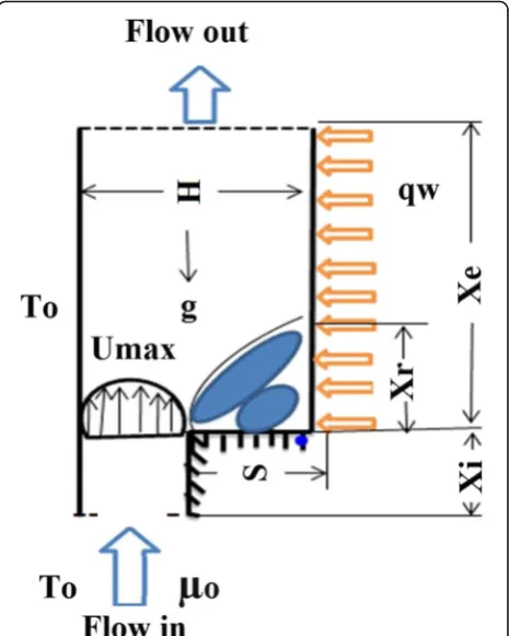
Figure1shows the geometrical arrangement for the
dir-ect step backward facing where the two parameters of the stepping height and expansion ratio were set at 4.8 mm and 2, respectively. Additionally, the upstream and downstream walls were assembled at 24 mm and 144
mm, respectively. At the wall, a uniform heat flux (qw)
was applied to the step downstream wall (Xe) while the
opposite wall of the channel was kept isothermally
con-sistent with the fluid temperature of T0. The wall
upstream is characterized by two steps: Xi and S; both
were kept under adiabatic surface condition. The
re-attachment length (Xr) is shown on the right side of the
bottom of the channel. At the channel entrance, the nanofluid stream is hydrodynamically persistent and the flow achieves the fully developed conditions at the edge of the movement which results in zero speed at the in-ternal surface of the pipe. The nanofluids (nanoparticles and water) were adjusted for specific heat flux to attain a no-slip condition. The flow was assumed to be incom-pressible and follows Newtonian fluid in regard to the viscosity. As an approximation, the exchange radiation heat flux, its counterpart distribution term, and the inward heat flux were dismissed. The thermophysical properties of the nanofluids are constant while the buoy-ancy was constrained as an opposing motion to the grav-ity. The Boussinesq equation is employed for this system.
FLUENT solver is based on the finite volume method. In this case, domain of the model to be examined is dis-cretized into a finite set of the control volumes, which are termed meshes or cells. Then, the general conserva-tion equaconserva-tions for mass, momentum, and energy solved on this set control volumes. Other transport equations such as the equations for species may also be applied. Subsequently, partial differential equations are discre-tized into a system of algebraic equations. All algebraic equations are solved numerically to render the solution
field. Computational fluid dynamic (CFD) theories, the CFD modeling process, physical model, and assumptions such as model, governing equations and boundary con-ditions, thermophysical properties of nanofluids, finite volume method (FVM), and fluid computation by the SIMPLE algorithm are presented in the following sec-tions. CFD techniques are used to study and solve com-plex fluid flow and heat transfer problems in the backward and forward double steps. CFD is a computer-based tool for simulating the behavior of systems involving fluid flow, heat transfer, and other physical-related processes. It works by solving the equations of fluid flow (in a special form) over a re-gion of interest, with specified (known) conditions on the boundary of that region. CFD has facilities in the industry as it can solve several system configura-tions in the same time and at a cheaper cost com-pared with other experimental studies. In the current study, a CFD technique is used to investigate the ef-fect of using nanofluids as work fluid instead of the
conventional fluids over backward and forward
double steps. The interest region where flow simula-tion is to be done is the computasimula-tional domain of the problems.
Cost analysis of using nanofluids To investigate the cost-effectiveness of using nanofluids as coolants, computational fluid dynamics method is employed to directly simulate the flow and heat transfer of the nanofluids in a 2-dimensional micro channel in the present paper. There are two different numerical methods for doing these. One is based on molecular dynamics which directly focuses on the molecular be-haviors of the nanoparticles. This method needs more CPU time and computer memory. The other is based on Navier-Stokes questions introducing the thermal and dynamic parameters of the nanofluids obtained from the mixture fluid theory and experimental mea-surements. Nanofluids are prepared by either one-step or two-step methods. Both methods require advanced and sophisticated equipment. This leads to higher production cost of nanofluids. Therefore, high cost of nanofluids is a drawback of nanofluid applications (Xu, Pan, & Yao, 2007).
Governing equations To prepare the CFD investigation of the reverse confronting step, it is imperative to set up the basic three equations which describe the
con-tinuity (Eq. 1), momentum (Eq. 2), and the energy
(Eq. 3). It is also important to set the non-dimensional
variables. In addition, the Boussinesq equation was used to deal with the viscous dispersal and compressibility impact. The conditions for two-dimensional laminar
incompressible streams can be composed as suggested
by (Abu-Nada,2008):
The continuity equation: ∂U
∂Xþ
∂V
∂Y¼0 ð1Þ
The momentum equations
X‐motion:U∂U
∂XþV
∂V
∂Y¼−
∂P
∂X
þ μnf
ρnυnf
1
Re
∂2U ∂X2þ
∂2U ∂Y2
Y‐motion:U∂U
∂XþV
∂V
∂Y¼−
∂P
∂Y
þμnf
ρnυnf
1
Re
∂2U ∂X2þ
∂2U ∂Y2
þð Þρβnf
ρnfβnf Gr Re2θ
ð2Þ
The energy equation:U∂θ
∂XþV
∂θ
∂Y¼
αnf
αfRePr
∂2θ ∂X2þ
∂2θ ∂Y2
ð3Þ
The dimensionless variables are defined as follows,
X ¼x
S Y ¼
y
S θ¼
T−T0
Tw−T0
U¼ u
U0
V ¼ v
V0
Re¼ρu0Dh μ
Boundary conditions The boundary conditions as shown below reflect the limiting situations at the walls in regard to the flow, no-slip condition, and temperature. The conditions at the channel segment include the temperature and the speed. The overall arrangement is governed by the following conditions (Ghasemi & Aminossadati,2010; Öztop,2006):
Upstream inlet:
X¼− Xi
Dh
S Dh≤Y≤
H
Dh U1¼
ui
uo V= 0 θ= 0
Downstream exit:
X¼ Xe
Dh 0≤Y≤
H
Dh ∂
2U
∂X2¼0 ∂ 2V
∂X2¼0 ∂ 2θ ∂X2¼0
Top wall:
− 1
Dh≤X≤
Xe
Dh Y¼
H
Dh U= 0 V= 0 θ= 0
Sidewalls:
− Xi
Dh≤X≤
Xe
Dh 0≤Y≤
H
Dh U= 0 V= 0 θ= 0
Stepped wall condition: (a) Upstream:
−Xi
Dh≤X≤0 Y¼
S
Dh U= 0 V= 0
∂θ
∂Y¼0
Stepped wall condition: (b) At the step:
X= 0 0≤Y≤ S
Dh U= 0 V= 0
∂θ
∂Y¼0
Stepped wall condition: (c) Downstream:
0<X≤ Xi
Dh Y= 0 U= 0 V= 0
∂θ
∂Y¼−1
A preliminary evaluation was adopted to coordinate the grid geometrical conditions and the ability of the grid to show the impact of heat transfer of the fluids with various NFs. The cross investigation was driven
with the working fluids, NFs, at Re= 50 and 175, while
keeping the downstream wall and the channel stream at
temperature difference ofΔT= 15 °C. Three grid size of
140 × 50, 128 × 50, and 140 × 60 were used for testing a self-governance system while a fourth grid size of 128 × 50 was maintained for self-governing independence tri-als. Several local trials have shown that using other grid sizes reduces the performance of the grid up to 4% in evaluating speed and temperature. The partition be-tween the center points was extended to reach 14 in the
x-direction while it reaches 3.5 in the y-direction. The
current examination has adopted a non-uniform struc-ture and quadrilateral sides. The system was specifically tested near the steps at the edge and the walls to guaran-tee the precision of the numerical deviation which helps remarkably to save both the computational time and cross assessment.
The second cross tests have improved the situation of
air flow atRe= 100 while a uniform heat flux progress
of qw= 200 W/m2was applied to the downstream wall.
The points of the cross-sectional center are set at dif-ferent sizes of the grid while the framework numbers in
thex-direction were 100, 120, and 140 and 50, 60, and
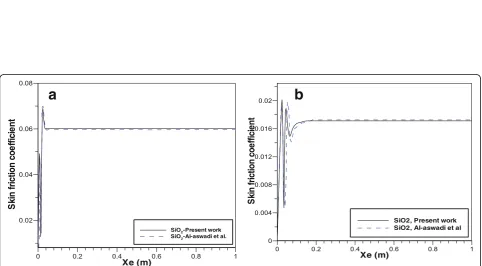
70 in they-heading to ensure the system flexibility test. A grid size of 100 × 50 was used to examine and then to validate the cross self-sufficient course of action. It
shows under 3% reduction in Nu and other grid sizes
that are mentioned in Table 1, a fine structure is used
as a part of the x-coordinate which is close to the
div-ider motion section, while it increases with expansion
of 0.1 in x-bearing along the way from the wall
pos-ition. Other fine grids of the improvement extents at
the ratio of 0.285 in the y-heading are utilized very
close to the base divider and the edge of the wall to
ensure the accuracy of the framework free course of action.
ii. Validation of the code
The numerical approval strategy that comprises the numerical code under particular conditions was tested and then used as a benchmark for afterward contrasting. The main experiment was performed by creating the constrained convective nanofluids stream over an even
BFS in a pipe (Al-Aswadi et al., 2010). For this stream,
Re numbers for the laminar flow were taken at 50 and
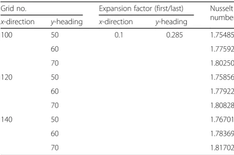
175. Figures 2, 3, and 4 demonstrate the consequences
of the correlation with the findings of the various NFs as presented by Al-Aswadi et al. (2010). The velocity distri-bution for different stepped wall increments (X/S) in the
distribution along the pipe is shown in Figs.2 and 3for
Al2O3 and CuO under same conditions, respectively.
The distribution location shows up and the measure of the local distribution diminishes as the separation between the stepX/Sachieves the reattachment condition at zero-speed flow as shown in Figs.2a–d and3a–d. Figures2a–c
and 3a–c demonstrate that a distribution location grew
continuously downstream. Additionally, the downstream of flow begins to end up completely by creating fluid stream toward the pipe exit as shown in Figs.2and3d.
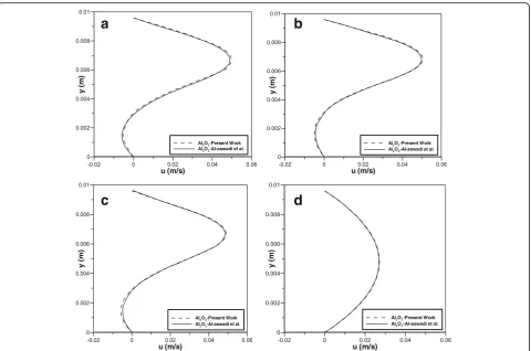
The skin friction coefficients shown in Fig. 4 were
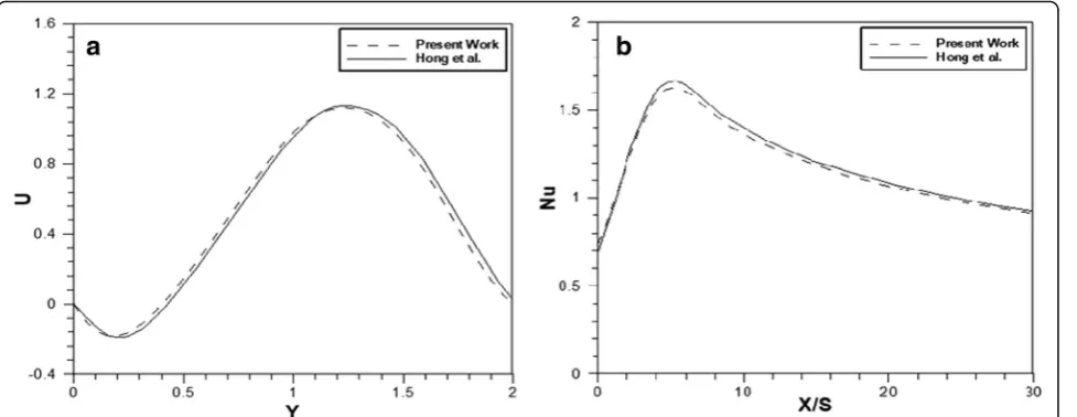
demonstrated at the base of the wall step showing that they achieve the separation downstream from the step showing the highest extreme base peak until achieving a consistent friction coefficient along the rest of the base wall. The condition of the flow to reach fully developed flow depends on the asymptotic variation of the skin coefficient. The second experiment was prepared to reproduce blended convective wind stream over BFS in the channel according to the work performed by Hong
et al. (1993). The conditions of this experiment include
setting Reat 100 and applying a uniform wall heat flux
at 200 W/m2. The velocity distribution and Nu at the
point whereθ°= 0 are explained in Fig.5a, b.
Procedure of numerical calculationThe procedure of
the numerical calculations was executed through
governing equations and the conditions alongside the limit as depicted in Eqs. (1) to (3). The conditions for the strong and fluid stage were considered as a single domain. The discretization of the conditions in the liquid and strong regions has come to an end by utilizing FVM. The diffusion term under energy and momentum conditions is approximated continuously by arranging the focal distinction until achieving a steady state condition. However, a second-arranged upstream procedure was prepared to show the relation to the con-vective terms. The calculation of the stream field was Table 1Grid tests for the Nusselt number atRe= 100
Grid no. Expansion factor (first/last) Nusselt number
x-direction y-heading x-direction y-heading
100 50 0.1 0.285 1.75485
60 1.77592
70 1.80250
120 50 1.75856
60 1.77922
70 1.80828
140 50 1.76701
60 1.78369
completely utilized by the SIMPLE calculation (John &
Anderson,1995). This was an iterative arrangement
meth-odology where the calculation is introduced through speculating the weight field. At this point, the momentum equations were utilized to determine the speed parts followed by refreshing the weight factor to reach the con-tinuity state. Despite the fact that the steady state does not contain any weight factor, it can be changed effortlessly into a weight adjustment condition (Patanker,1980).
Thermophysical characteristics of nanofluidsThe zinc oxide (ZnO) nanoparticles were synthesized using a simple precipitation method with zinc sulfate and sodium hydroxide as starting materials. The synthesized sample was calcined at different temperatures for 2 h (Kumar, Venkateswarlu, Rao, & Rao,2013); copper oxide (CuO) is the inorganic compound with the formula CuO. As a black solid, it is one of the two stable oxides of copper, the
other being Cu2O or cuprous oxide. As a mineral, it is
known as tenorite. It is a product of copper mining and the precursor to many other copper-containing products
and chemical compounds (Richardson, 2002). Silicon
dioxide (SiO2), also known as silica, is an oxide of silicon
with the chemical formula SiO2, most commonly found in
nature as quartz and in various living organisms (Fernández, Lara, & Mitchell, 2015; Iler, 1979). In many parts of the world, silica is the major constituent of sand. Silica is one of the most complex and most abundant families of materials, existing as a compound of several minerals and as a syn-thetic product. Notable examples include fused quartz, fumed silica, silica gel, and aerogels. It is used in structural materials and microelectronics (as an electrical insulator) and as components in the food and pharmaceutical
indus-tries. Aluminium oxide (Al2O3) (IUPAC name) or
aluminum oxide (American English) is a chemical com-pound of aluminum and oxygen with the chemical formula
(Al2O3). It is the most commonly occurring of several
aluminum oxides and specifically identified as aluminum (III) oxide. It is commonly called alumina and may also be called aloxide, aloxite, or alundum depending on particular forms or applications. It occurs naturally in its crystalline polymorphic phaseα-Al2O3as the mineral corundum,
var-ieties of which form the precious gemstones ruby and sap-phire. Al2O3 is significant in its use to produce aluminum
metal, as an abrasive owing to its hardness and as a refrac-tory material owing to its high melting point (Davis,1993).
With a specific end goal to complete simulation for NFs, the compelling thermophysical characteristics of
a
b
c
d
Fig. 3Comparison of velocity distribution with the results of Al-Aswadi et al. (2010) in the recirculation region forS= 4.8 mm, andER= 2 atRe=175. For CuO at differentX/S:a1.04,b1.92,c2.6,d32.8
a
b
NFs must be first determined. For this situation, the
nanoparticles are Al2O3, CaO, ZnO, and SiO2. The
required properties for the recreations are to set the effective heat conductivity (keff), to calculate the effective
viscosity (μeff) and effective density (ρeff), and to assume
that the effective coefficient of heat expansion (βeff) and
effective particular heat capacity (cpeff) are following the
incompressible fluid and their estimation depends on
the volume fraction of their nanofluid (∅). By utilizing
Brownian movement of nanoparticles in reverse
confronting step, the effective heat flux conductivity can
be acquired as following mean experimental
requirements (Ghasemi & Aminossadati, 2010; Heidari,
Mohebbi, & Safarzade,2016):
keff¼kstaticþkBrownian ð4Þ
wherekstaticis defined as,
kstatic ¼kbf
knpþ2kbf−2 kbf−knp
∅
knpþ2kbf þ2 kbf−knp
∅
" #
ð4:1Þ
and the Brownian thermal conductivity,
kBrownian¼5104β∅cp;bf
ffiffiffiffiffiffiffiffiffiffiffiffiffiffiffiffi kT 2ρnpRnp s
f Tð ;∅Þ ð4:2Þ
where Boltzmann constant:
k¼1:380710−23 J=K βAl2O3¼8:4407 100ð ∅Þ−
1:07304
βCuO¼9:881 100ð ∅Þ− 0:9446
Modeling function,β(Vajjha & Das,2009):
βSiO2¼1:9526 100ð ∅Þ −1:4594
βZnO¼8:4407 100ð ∅Þ −1:07304
Modeling function
f Tð ;∅Þ ¼2:821710−2∅þ3:91710−3Þ T T0
þ−3:069910−2∅−3:9112310−3
andμeffcan be empirically estimated (Corcione,2010):
μeff¼
μf
1−34:87 dp
df
−0:3 ∅1:03
ð5Þ
where,
The equivalent diameter isdeff ¼
6M Nπρbt
1=3
ð6Þ
The density of NF 68½ isρnf
¼ð1−∅Þρf þ∅ρnf ð7Þ
The effective heat capacity at constant pressure of NF (Ghasemi & Aminossadati,2010) is:
cp nf ¼ð1−∅Þ cp fþ∅ cp np ð8Þ
The effective coefficient of thermal expansion of nanofluid (Ghasemi & Aminossadati,2010):
β
ð Þnf ¼ð1−∅Þð Þβ f þ∅ð Þβ np ð9Þ
The experimental values of the thermophysical
properties for pure water with different NFs at 300 K are listed in Table2.
Fig. 5Comparison of the present results with the results of Hong et al. (1993) (S= 4.8 mm, andER= 2) forRe=100, andqw= 200 W/m2(X= 3) at
Results and discussion Reattachment zone
The zone was allocated to display the numerical results to test the 2-D vertical mixed convective stream by standing up the step. The results of speed distribution and skin friction coefficient were taken at different
values of Nu at various nanofluids at hand, various
nanoparticle volume fractions, Reynolds numbers, and varying heat flux and the height of the wall, and finally with varying nanoparticle diameters. The Reynolds num-ber was taken between 100 and 500 while the heat flux
was considered between 100 and 600 W/m2. The stream
reaches out from a totally developed upstream to outline a basic circulation region. Starting forward, the speed profile is reattached and redeveloped pushing toward a totally developed stream as fluid streams toward chan-nels exit.
Nanofluid parameters’impacts
The nanoparticles with water as a base fluid of Al2O3,
CaO, ZnO, and SiO2were used. The impact of various
nanofluids on the heat transfer enhancement was tested
under the following parameters of∅= 0.04, dp= 25 nm,
Re= 100, and qw= 500 W/m2 along the channel.
Figure 6a shows that Nuacquires the highest value near
the wall due to an increasing heating of the wall which decreases steadily as the detachment continues. This is a result of the temperature refinement when the exchanged stream is joined to the essential separated stream which
has a lower temperature. It is found that SiO2nanofluid
has the highest Nu peak followed by Al2O3, CuO, and
finally ZnO. The results mentioned can be explained in terms of how much is the reduction in the fluid viscosity and the effect of the heat flux since the viscosity is very critical to these two factors.
This study also shows the effect of ∅ between 1 and
4% on the characteristics of the heat transfer as
illustrated in Fig. 6b under the conditions of
nanoparticle dp= 25 nm, Re= 100, and qw= 500 W/m2.
As ∅ increases, the Nu of SiO2 nanofluids ends up
higher than that of unadulterated fluids. This is because of the density increasing which prompts the heat
transfer enhancement as showed in Fig. 6b. A possible
explanation to this could be referred to the effect of the
decreasing temperature refinement as∅increases which
results in increasing the heat transfer improvement. The impact of the diameter of nanoparticles on the heat transfer reveals that the heat transfer varies significantly with the mean nanoparticle diameter between 25 and 80
nm, atRe= 100,∅= 4%, andqw= 500 W/m2.
Figure 6c shows the eventual outcome of Nu when
SiO2 nanofluids were used. It has been shown that the
mean nanofluid diameter increases due to the increasing
Nu. This is because the nanofluid properties such as
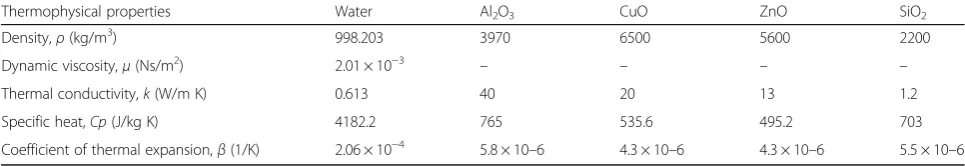
density and heat capacity increase with a decreasing nanoparticle volume ratio which affects the surface area. Thus, the small diameter of the nanoparticles results in increasing the heat transfer improvement. Consequently, Table 2Thermophysical properties for pure water and different nanofluids atT= 300 K (Corcione,2010)
Thermophysical properties Water Al2O3 CuO ZnO SiO2
Density,ρ(kg/m3) 998.203 3970 6500 5600 2200
Dynamic viscosity,μ(Ns/m2) 2.01 × 10⁻³ – – – –
Thermal conductivity,k(W/m K) 0.613 40 20 13 1.2
Specific heat,Cp(J/kg K) 4182.2 765 535.6 495.2 703
Coefficient of thermal expansion,β(1/K) 2.06 × 10⁻⁴ 5.8 × 10⁻⁶ 4.3 × 10⁻⁶ 4.3 × 10⁻⁶ 5.5 × 10⁻⁶
a
b
c
Fig. 6The effect of nanofluid parameters along the downstream wall atRe= 100,qw= 500 W/m2,∅= 4%, anddp= 25 nm foradifferent
Nu increases as the diameter of the nanoparticles increases.
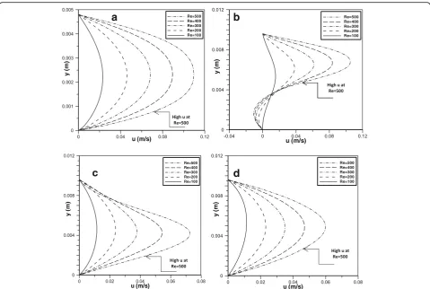
Different Reynolds numbers’impacts Distribution of the velocity
Figure7shows the speed circulations of SiO2nanofluid at
Re numbers in the scope of 100≤Re≤500, qw= 500 W/
m2,dp= 25 nm, and∅= 4% at variousX/Ssections along
the stepped wall. In Fig. 7a, as Re increases, the speed
profile for SiO2 nanofluid becomes more profound and
illustrative. The speed increases as Re increases until
reaching the distribution at which the flow reached the reattachment. It has been noted that as the separation between the step and the stepped wall increase, the flow achieves the reattachment faster and the span of the
distribution area diminishes as Re expands further as
shown in Fig. 7b, c. Beyond this point, the downstream
shows that the flow begins to redevelop until reaching completely developed flow at the exit as shown in Fig.7d.
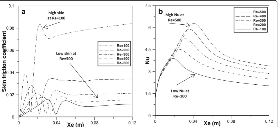
Coefficient of skin friction
Figure 8a explains the behavior of the skin friction
coefficient of the SiO2 nanofluid at Re in the scope of
100≤ Re≤500, ∅= 4%, qw= 500 W/m2, and dp= 25 nm
along the downstream wall. It is shown that the skin
friction coefficient decreases rapidly as Re increases.
Additionally, it is seen that the crests at and close to the essential local distribution are displaced along the way from the wall divider in the streamwise bearing asReincreases. This increase comes with the increasing of the length differential of the essential distribution region. The behavior of the coefficient of friction is inversely proportional.
Nusselt number
The Nu of SiO2 nanofluid at Re between 100 and 500,
∅= 4%, qw= 500 W/m2, and dp= 25 nm along the
downstream wall is plotted in Fig. 8b. It is shown that
Nu increases as Re increases exhibiting stronger
convective current which is caused by the reduction in
the isotherms. The behavior ofNushows an exponential
reduction from its optimal level until the vortex is
started forming. At the highest Re, the stream decreases
to the minimum apex of the Nu number at the region
where the flows are mixed. Along this zone, theNuSiO2
nanofluid was found to possess higher values as Re
number increases.
a
b
c
d
Fig. 7Velocity distributions of SiO2nanofluid with∅= 4%, anddp= 25 nm at differentReforqw= 500 W/m2ataX/S= 0,bX/S= 1.8,cX/S=
Various heat fluxes’impacts Distribution of the velocity
Figure 9 shows the speed distribution of SiO2
nanofluid at qw varies between 100 and 600 W/m
2
,
Re= 100, dp= 25 nm, and ∅= 4% along the X/S
sections. It seems that there is an insignificant effect at the edge region, as the stream profiles show no
pattern difference as shown in Fig. 9a.
However, the degree of the circulation area expands as the heat transfer increases between the heated stepped
wall and the stream of the nanofluid as shown in Fig.9b,
c. It was also found that the buoyancy force slightly pushes up the fast stream and cutting down heat flux and increasing the reattachment length. As the divisions,
X/S along the wall increases the circulation zone
decreases as shown in Fig. 9b, c. At this location, the
flow starts to redevelop approaching full developing stream flow at the exit according to Fig.9d.
Skin friction coefficient
The testing of the skin friction of SiO2 nanofluid was
carried out with∅= 4%, anddp= 25 nm, heat flux in the
scope of 100≪qw≪600 W/m2, and Re= 100 along the
downstream divider are shown in Fig.10a. It is observed
that the increase in the heat flow enhances the skin friction coefficient. However, at a particular heat flux of qw= 600 W/m2, the skin friction coefficient shows higher values due to the diminishing shear stress at the vortex.
Nusselt number
Figure 10b explains the behavior of Nu-SiO2 with ∅=
4%,dp= 25 nm, heat flux of 100≪qw≪600 W/m2, and
Re= 100 along the downstream divider. Asqwincreases,
it was noticed that the highest value ofNudecreases due
to the increasing effect of the expanding buoyancy force. It is important to note that the reduction of optimized
Nucontinues until roughly the exiting point. The results
show that the stream with high heat flow possesses the
most astounding Nuleast peak in the region where the
flows are mixed. It was also found that alongside this
territory, Nu with SiO2nanofluid possesses the highest
value when the heat flow is at the highest value.
Conclusions
Numerical simulation for laminar blended convection stream in a vertical 2-D backward-facing step channel configuration was investigated under a variety of param-eters and initial conditions. This topic has recently gained special importance especially due to consolidating
Re and nanofluids such as aluminum, copper(II) oxide,
zinc oxide, and silicon dioxide with water. Reynolds
number was chosen within 100≪ Re ≤500, diameter of
nanoparticles dp: [25, 80] nm, and ∅: [1%, 4%]. The
backward-facing step downstream flow has reached its uniform condition at the uniform heat flux between 100
and 600 W/m2while the channel particular propel
stat-ures were taken in the extent of 3.0≪S≪5.8 mm. The
governing equations have shown very good agreement with the solution using FVM with specific suppositions coupled with proper limit conditions. The current inves-tigation examined the influence of the stream and its relevant opposing flow on the properties of the heat flux.
The following conclusions are drawn from this
investigation:
a
b
Fig. 8The effect ofReof SiO2nanofluid with∅= 4%, and dp= 25,qw= 500 W/m2along the downstream wall.aSkin friction coefficient.b
Fig. 10The effect of heat flux of SiO2nanofluid with∅= 4%, anddp= 25,Re= 100 along the downstream wall.aSkin friction coefficient.bNusselt number
Fig. 9Velocity distributions of SiO2nanofluid withφ= 4%, anddp= 25 nm at different heat fluxes forRe= 100 ataX/S= 0,bX/S= 1.8,cX/S= 12.82,
1. SiO2nanoparticles show the most astoundingNu
followed by Al2O3, CaO, and ZnO.
2. Nuincreased continuously by expandingReand by increasing the step height as well. It was also observed thatNuincreases as the heat flux
increases. However,Nuis slowly diminishing as the nanofraction diminishes.
3. The present work creates a region of a straight downstream distribution for blended convection stream at variousReand heat flux. It was found that this distribution is highly dependent on increasingRe. The best location of this distributing region was allocated at the interface of the corner where the stepping height joins the downstream wall.
4. The heat flux was found very dependent on the conditions that correlate the preferred flux exchange rate over restricting stream condition.
Nomenclature A Area (m2)
Al2O3Aluminum oxide
ArAspect ratio
BFS Backward-facing step cpSpecific heat (kJ/kg K)
CFD Computational fluid dynamic CuO Copper oxide
dpDiameter of nanofluid particles (nm)
FVM Finite volume method
DhHydraulic diameter at inlet (m)
ER Expansion ratio, H/S
eExpansion successive ratio
FFS Forward-facing step fElliptic relaxation function GrGrashof number, gβΔTS3/v2 gGravitational acceleration (m/s2)
HTotal channel height (m)
h Inlet channel height (m)
hConvective heat transfer coefficient (W/m2K)
H2O Water
k Thermal conductivity (W/m K) kTurbulent kinetic energy (m2/s2)
SStep height (m)
SiO2Silicon dioxide
LTotal length channel (m)
Nu Nusselt number,hs/k
Nus, maxMaximum Nusselt number,hs/k
PNodal point number of processors
pPressure (pa)
paPressure at the outlet (pa)
PrPrandtl number,μCp/k
qwWall heat flux (W/m2)
ReReynolds number,ρuoDh/μ
RiRichardson number, Gr/Re2
TTemperature (K)
TwHeat wall temperature (K)
ToTemperature at the inlet, outlet, or top wall (K) UHF Uniform heat flux
UDimensionless streamwise velocity component,u/uo
uVelocity componentx-direction (m/s)
uoAverage velocity for inlet flow (m/s)
u∞Free-stream velocity (m/s)
VDimensionless transverse velocity component,v/uo
vVelocity componenty-direction (m/s)
XDimensionless length atx-coordinate,x/S
x x-Coordinate direction (m)
XeDownstream wall length (m)
XiUpstream wall length (m)
XnNusselt number peak length (m)
XoSecondary recirculation length (m)
XrReattachment length (m)
Y Dimensionless length aty-coordinate,y/S
y y-Coordinate direction (m)
ZnO Zinc oxide
Greek symbols ρDensity (kg/m3)
βThermal expansion coefficient, (1/K)
υKinematic viscosity (m2/s)
φVolume fraction (%)
μDynamic viscosity (N m/s)
αThermal diffusivity of the fluid (m2/s)
ΔAmount of difference
Dimensionless temperature, (T−To)/(Tw−To)
Subscripts bfBase fluid
iInlet oOutlet fFluid
nfNanofluid
sSolid (nanoparticles) W Wall
Acknowledgements
The authors gratefully acknowledge the Al-Furat Al Awsat Technical University‘Iraq’for supporting this work.
Authors’contributions
AAA-O and AJC carried out the experiments. ARY, MHM, and DHA collected the data and did the validation. AAH and MST supervised the project. AAA wrote the manuscript with support from TSG. All authors read and approved the final manuscript.
Funding
UKM-YSD Grant 020–2017
Availability of data and materials
All data generated or analyzed during this study are included in this published article.
Competing interests
Author details
1Department of Power Mechanics, Technical Institute of Babylon, Al-Furat Al Awsat Technical University, Babil, Iraq.2Technical College Al-Musaib, Al-Furat Al Awsat Technical University, Al-Musaib, Babil 51009, Iraq.3Faculty of Engineering & Built Environment, Universiti Kebangsaan Malaysia, 43600 Bangi, Selangor, Malaysia.4Energy and Renewable Energies Technology Center, University of Technology, Baghdad 10001, Iraq.
Received: 8 March 2019 Accepted: 8 July 2019
References
Abchouyeh, M. A., Mohebbi, R., & Fard, O. S. (2018). Lattice Boltzmann simulation of nanofluid natural convection heat transfer in a channel with a sinusoidal obstacle.International Journal of Modern Physics C, 29, 1850079.
Abe, K., Kondoh, T., & Nagano, Y. (1995). A new turbulence model for predicting fluid flow and heat transfer in separating and reattaching flows—II. Thermal field calculations.International Journal of Heat and Mass Transfer, 38, 1467–1481.
Abu-Mulaweh, H. (2003). A review of research on laminar mixed convection flow over backward-and forward-facing steps.International Journal of Thermal Sciences, 42, 897–909.
Abu-Mulaweh, H., Armaly, B. F., & Chen, T. (1993). Measurements of laminar mixed convection in boundary-layer flow over horizontal and inclined backward-facing steps.International Journal of Heat and Mass Transfer, 36, 1883–1895.
Abu-Nada, E. (2008). Application of nanofluids for heat transfer enhancement of separated flows encountered in a backward facing step.International Journal of Heat and Fluid Flow, 29, 242–249.
Al-Aswadi, A., Mohammed, H., Shuaib, N., & Campo, A. (2010). Laminar forced convection flow over a backward facing step using nanofluids.International Communications in Heat and Mass Transfer, 37, 950–957.
Alawi, O., Azwadi, C. N., Kazi, S., & Abdolbaqi, M. K. (2016). Comparative study on heat transfer enhancement and nanofluids flow over backward and forward facing steps.Journal of Advanced Research in Fluid Mechanics and Thermal Sciences, 23, 25–49.
Al-Shamani, A. N., Sopian, K., Mohammed, H., Mat, S., Ruslan, M. H., & Abed, A. M. (2015). Enhancement heat transfer characteristics in the channel with trapezoidal rib–groove using nanofluids.Case Studies in Thermal Engineering, 5, 48–58.
Armaly, B. F., Durst, F., Pereira, J., & Schönung, B. (1983). Experimental and theoretical investigation of backward-facing step flow.Journal of Fluid Mechanics, 127, 473–496.
Blackwell, B., & Armaly, B. (1993). Computational aspects of heat transfer benchmark problems.ASME HTD, 258, 1–10.
Bomela, C. L. (2014).The effects of inlet temperature and turbulence characteristics on the flow development inside a gas turbine exhaust diffuser. Charlotte: The University of North Carolina.
Chen, Y., Nie, J., Armaly, B., & Hsieh, H.-T. (2006). Turbulent separated convection flow adjacent to backward-facing step—effects of step height.International Journal of Heat and Mass Transfer, 49, 3670–3680.
Corcione, M. (2010). Heat transfer features of buoyancy-driven nanofluids inside rectangular enclosures differentially heated at the sidewalls.International Journal of Thermal Sciences, 49, 1536–1546.
D’Adamo, J., Sosa, R., & Artana, G. (2014). Active control of a backward facing step flow with plasma actuators.Journal of Fluids Engineering, 136, 121105. Daungthongsuk, W., & Wongwises, S. (2007). A critical review of convective heat
transfer of nanofluids.Renewable and Sustainable Energy Reviews, 11, 797–817. Davis, J. R. (1993).Aluminum and aluminum alloys: ASM international.
Delouei, A. A., Sajjadi, H., Izadi, M., & Mohebbi, R. (2019). The simultaneous effects of nanoparticles and ultrasonic vibration on inlet turbulent flow: an experimental study.Applied Thermal Engineering, 146, 268–277.
Denham, M., & Patrick, M. (1974). Laminar flow over a downstream-facing step in a two-dimensional flow channel.Transactions of the Institution of Chemical Engineers, 52, 361–367.
Fernández, L. D., Lara, E., & Mitchell, E. A. (2015). Checklist, diversity and distribution of testate amoebae in Chile.European Journal of Protistology, 51, 409–424.
Gartling, D. K. (1990). A test problem for outflow boundary conditions—Flow over a backward-facing step.International Journal for Numerical Methods in Fluids, 11, 953–967.
Ghasemi, B., & Aminossadati, S. (2010). Brownian motion of nanoparticles in a triangular enclosure with natural convection.International Journal of Thermal Sciences, 49, 931–940.
Hasan, H. A., Sopian, K., Jaaz, A. H., & Al-Shamani, A. N. (2017). Experimental investigation of jet array nanofluids impingement in photovoltaic/thermal collector.Solar Energy, 144, 321–334.
Hashemi, Z., Abouali, O., & Ahmadi, G. (2017). Direct numerical simulation of particle–fluid interactions: a review.Iranian Journal of Science and Technology, Transactions of Mechanical Engineering, 41, 71–89.
Hashim, W. M., Shomran, A. T., Jurmut, H. A., Gaaz, T. S., Kadhum, A. A. H., & Al-Amiery, A. A. (2018). Case study on solar water heating for flat plate collector.
Case Studies in Thermal Engineering, 12, 666–671.
Heidari, H., Mohebbi, R., & Safarzade, A. (2016). Parameter estimation in fractional convection-diffusion equation.PONTE International Scientific Research Journal, 72, 55–68.
Hong, B., Armaly, B. F., & Chen, T. (1993). Laminar mixed convection in a duct with a backward-facing step: The effects of inclination angle and Prandtl number.International Journal of Heat and Mass Transfer, 36, 3059–3067. Iler, R. K. (1979).The chemistry of silica(pp. 30–62). New York: Wiley. Iwai, H., Nakabe, K., Suzuki, K., & Matsubara, K. (2000). The effects of duct
inclination angle on laminar mixed convective flows over a backward-facing step.International Journal of Heat and Mass Transfer, 43, 473–485. Izadi, M., Hoghoughi, G., Mohebbi, R., & Sheremet, M. (2018). Nanoparticle
migration and natural convection heat transfer of Cu-water nanofluid inside a porous undulant-wall enclosure using LTNE and two-phase model.Journal of Molecular Liquids, 261, 357–372.
Izadi, M., Mohebbi, R., Chamkha, A., & Pop, I. (2018). Effects of cavity and heat source aspect ratios on natural convection of a nanofluid in a C-shaped cavity using Lattice Boltzmann method.International Journal of Numerical Methods for Heat & Fluid Flow, 28, 1930–1955.
Izadi, M., Mohebbi, R., Karimi, D., & Sheremet, M. A. (2018). Numerical simulation of natural convection heat transfer inside a┴shaped cavity filled by a MWCNT-Fe3O4/water hybrid nanofluids using LBM.Chemical Engineering and Processing-Process Intensification, 125, 56–66.
Jaaz, A., Hasan, H., Sopian, K., Kadhum, A., Gaaz, T., & Al-Amiery, A. (2017). Outdoor performance analysis of a photovoltaic thermal (PVT) collector with jet impingement and compound parabolic concentrator (CPC).Materials, 10, 888. Jaaz, A. H., Sopian, K., & Gaaz, T. S. (2018). Study of the electrical and thermal
performances of photovoltaic thermal collector-compound parabolic concentrated.Results in Physics, 9, 500–510.
John, D., & Anderson, J. (1995). Computational fluid dynamics: the basics with applications. InMechanical Engineering Series. Sydney: McGraw-Hill. Kherbeet, A. S., Mohammed, H., Salman, B., Ahmed, H. E., Alawi, O. A., & Rashidi,
M. (2015). Experimental study of nanofluid flow and heat transfer over microscale backward- and forward-facing steps.Experimental Thermal and Fluid Science, 65, 13–21.
Kumar, A., & Dhiman, A. K. (2012). Effect of a circular cylinder on separated forced convection at a backward-facing step.International Journal of Thermal Sciences, 52, 176–185.
Kumar, S. S., Venkateswarlu, P., Rao, V. R., & Rao, G. N. (2013). Synthesis, characterization and optical properties of zinc oxide nanoparticles.
International Nano Letters, 3, 30.
Ma, Y., Mohebbi, R., Rashidi, M., & Yang, Z. (2018a). Study of nanofluid forced convection heat transfer in a bent channel by means of lattice Boltzmann method.Physics of Fluids, 30, 032001.
Ma, Y., Mohebbi, R., Rashidi, M., & Yang, Z. (2019). MHD forced convection of MWCNT–Fe 3 O 4/water hybrid nanofluid in a partially heatedτ-shaped channel using LBM.Journal of Thermal Analysis and Calorimetry, 136(4), 1723–1735.
Ma, Y., Mohebbi, R., Rashidi, M., & Yang, Z. (2018b). Simulation of nanofluid natural convection in a U-shaped cavity equipped by a heating obstacle: Effect of cavity's aspect ratio.Journal of the Taiwan Institute of Chemical Engineers, 93, 263–276.
Ma, Y., Mohebbi, R., Rashidi, M., & Yang, Z. (2018c). Numerical simulation of flow over a square cylinder with upstream and downstream circular bar using lattice Boltzmann method.International Journal of Modern Physics C, 29, 1850030. Ma, Y., Mohebbi, R., Rashidi, M., Yang, Z., & Sheremet, M. A. (2019). Numerical
study of MHD nanofluid natural convection in a baffled U-shaped enclosure.
International Journal of Heat and Mass Transfer, 130, 123–134. Ma, Y., Mohebbi, R., Rashidi, M. M., Manca, O., & Yang, Z. (2018). Numerical
enclosure using lattice Boltzmann method.Journal of Thermal Analysis and Calorimetry, 135(6), 3197–3213.
Ma, Y., Mohebbi, R., Rashidi, M. M., & Yang, Z. (2019). Effect of hot obstacle position on natural convection heat transfer of MWCNTs-water nanofluid in U-shaped enclosure using lattice Boltzmann method.International Journal of Numerical Methods for Heat & Fluid Flow, 29, 223–250.
Mohammed, H., Al-Aswadi, A., Shuaib, N., & Saidur, R. (2011). Convective heat transfer and fluid flow study over a step using nanofluids: a review.
Renewable and Sustainable Energy Reviews, 15, 2921–2939.
Mohammed, H., Al-Aswadi, A., Yusoff, M., & Saidur, R. (2012). Mixed convective flows over backward facing step in a vertical duct using various nanofluids-buoyancy-assisting case.Thermophysics and Aeromechanics, 42, 1–30. Mohammed, H., Alawi, O., & Sidik, N. C. (2016). Mixed convective nanofluids flow
in a channel having forward-facing step with baffle.Journal of Advanced Research in Applied Mechanics, 24, 1–21.
Mohammed, H., Alawi, O. A., & Wahid, M. (2015). Mixed convective nanofluid flow in a channel having backward-facing step with a baffle.Powder Technology, 275, 329–343.
Mohebbi, R., & Heidari, H. (2017). Lattice Boltzmann simulation of fluid flow and heat transfer in a parallel-plate channel with transverse rectangular cavities.
International Journal of Modern Physics C, 28, 1750042.
Mohebbi, R., Izadi, M., & Chamkha, A. J. (2017). Heat source location and natural convection in a C-shaped enclosure saturated by a nanofluid.Physics of Fluids, 29, 122009.
Mohebbi, R., Izadi, M., Delouei, A. A., & Sajjadi, H. (2019). Effect of MWCNT–Fe 3 O 4/water hybrid nanofluid on the thermal performance of ribbed channel with apart sections of heating and cooling.Journal of Thermal Analysis and Calorimetry, 135, 3029–3042.
Mohebbi, R., Lakzayi, H., Sidik, N. A. C., & Japar, W. M. A. A. (2018). Lattice Boltzmann method based study of the heat transfer augmentation associated with Cu/water nanofluid in a channel with surface mounted blocks.International Journal of Heat and Mass Transfer, 117, 425–435. Mohebbi, R., Nazari, M., & Kayhani, M. (2016). Comparative study of forced
convection of a power-law fluid in a channel with a built-in square cylinder.
Journal of Applied Mechanics and Technical Physics, 57, 55–68. Mohebbi, R., & Rashidi, M. (2017). Numerical simulation of natural convection
heat transfer of a nanofluid in an L-shaped enclosure with a heating obstacle.Journal of the Taiwan Institute of Chemical Engineers, 72, 70–84. Mohebbi, R., Rashidi, M., Izadi, M., Sidik, N. A. C., & Xian, H. W. (2018). Forced
convection of nanofluids in an extended surfaces channel using lattice Boltzmann method.International Journal of Heat and Mass Transfer, 117, 1291–1303.
Murshed, S. S., De Castro, C. N., Lourenço, M., Lopes, M., & Santos, F. (2011). A review of boiling and convective heat transfer with nanofluids.Renewable and Sustainable Energy Reviews, 15, 2342–2354.
Nazari, M., Kayhani, M., & Mohebbi, R. (2013). Heat transfer enhancement in a channel partially filled with a porous block: lattice Boltzmann method.
International Journal of Modern Physics C, 24, 1350060.
Nazari, M., Mohebbi, R., & Kayhani, M. (2014). Power-law fluid flow and heat transfer in a channel with a built-in porous square cylinder: lattice Boltzmann simulation.Journal of Non-Newtonian Fluid Mechanics, 204, 38–49. Nie, J., & Armaly, B. F. (2002). Three-dimensional convective flow adjacent to
backward-facing step-effects of step height.International Journal of Heat and Mass Transfer, 45, 2431–2438.
Nikkhah, Z., Karimipour, A., Safaei, M. R., Forghani-Tehrani, P., Goodarzi, M., Dahari, M., et al. (2015). Forced convective heat transfer of water/functionalized multi-walled carbon nanotube nanofluids in a microchannel with oscillating heat flux and slip boundary condition.International Communications in Heat and Mass Transfer, 68, 69–77.
Öztop, H. F. (2006). Turbulence forced convection heat transfer over double forward facing step flow.International Communications in Heat and Mass Transfer, 33, 508–517.
Park, T. S., & Sung, H. J. (1995). A nonlinear low-Reynolds-numberκ-εmodel for turbulent separated and reattaching flows—I. Flow field computations.
International Journal of Heat and Mass Transfer, 38, 2657–2666.
Patanker, S. (1980).Numerical heat transfer and fluid flow. New York: Hemisphere Publishing Corporation.
Ranjbar, P., Mohebbi, R., & Heidari, H. (2018). Numerical investigation of nanofluids heat transfer in a channel consisting of rectangular cavities by lattice Boltzmann method.International Journal of Modern Physics C (IJMPC), 29, 1–23.
Rhee, G. H., & Sung, H. J. (1996). A nonlinear low-Reynolds-number k-εmodel for turbulent separated and reattaching flows—II. Thermal field computations.
International Journal of Heat and Mass Transfer, 39, 3465–3474. Richardson, H. W. (2002).Copper compounds in Ullmann’s encyclopedia of
industrial chemistry. Weinheim: Wiley-VCH.
Safaei, M., Togun, H., Vafai, K., Kazi, S., & Badarudin, A. (2014). Investigation of heat transfer enhancement in a forward-facing contracting channel using FMWCNT nanofluids.Numerical Heat Transfer, Part A: Applications, 66, 1321–1340. Saidur, R., Leong, K., & Mohammad, H. (2011). A review on applications and
challenges of nanofluids.Renewable and Sustainable Energy Reviews, 15, 1646–1668.
Selimefendigil, F., & Öztop, H. F. (2015). Numerical investigation and reduced order model of mixed convection at a backward facing step with a rotating cylinder subjected to nanofluid.Computers & Fluids, 109, 27–37.
Sheikholeslami, M., & Chamkha, A. J. (2016). Flow and convective heat transfer of a ferro-nanofluid in a double-sided lid-driven cavity with a wavy wall in the presence of a variable magnetic field.Numerical Heat Transfer, Part A: Applications, 69, 1186–1200.
Sheikholeslami, M., & Ganji, D. (2016). Nanofluid convective heat transfer using semi analytical and numerical approaches: a review.Journal of the Taiwan Institute of Chemical Engineers, 65, 43–77.
Trisaksri, V., & Wongwises, S. (2007). Critical review of heat transfer characteristics of nanofluids.Renewable and Sustainable Energy Reviews, 11, 512–523. Tylli, N., Kaiktsis, L., & Ineichen, B. (2002). Sidewall effects in flow over a
backward-facing step: experiments and numerical simulations.Physics of Fluids, 14, 3835–3845.
Vajjha, R. S., & Das, D. K. (2009). Experimental determination of thermal conductivity of three nanofluids and development of new correlations.
International Journal of Heat and Mass Transfer, 52, 4675–4682.
Wang, X.-Q., & Mujumdar, A. S. (2007). Heat transfer characteristics of nanofluids: a review.International Journal of Thermal Sciences, 46, 1–19.
Williams, P., & Baker, A. (1997). Numerical simulations of laminar flow over a 3D backward-facing step.International Journal for Numerical Methods in Fluids, 24, 1159–1183.
Xu, D., Pan, L., & Yao, Q. (2007). Heat transfer cost-effectiveness of nanofluids. In
Cleantech 2007: the Cleantech Conference, Venture Forum and Trade Show, May 23–24, 2007, Santa Clara, California, USA(p. 79).
Yu, W., & Xie, H. (2012). A review on nanofluids: preparation, stability mechanisms, and applications.Journal of Nanomaterials, 2012, 1.
Publisher’s Note