Mech. Sci., 9, 91–102, 2018
https://doi.org/10.5194/ms-9-91-2018
© Author(s) 2018. This work is distributed under the Creative Commons Attribution 4.0 License.
Mechanical behaviour of a creased thin strip
Jie Liu1,2, Shanqing Xu1, Guilin Wen2, and Yi Min Xie1,3 1Centre for Innovative Structures and Materials, School of Engineering,
RMIT University, Melbourne 3001, Australia
2State Key Laboratory of Advanced Design and Manufacturing for Vehicle Body,
Hunan University, Changsha 410082, China
3XIE Archi-Structure Design (Shanghai) Co., Ltd., Shanghai 200092, China
Correspondence:Yi Min Xie (mike.xie@rmit.edu.au)
Received: 20 October 2017 – Revised: 22 December 2017 – Accepted: 30 January 2018 – Published: 20 February 2018
Abstract. In this study the mechanical behaviour of a creased thin strip under opposite-sense bending was in-vestigated. It was found that a simple crease, which led to the increase of the second moment of area, could significantly alter the overall mechanical behaviour of a thin strip, for example the peak moment could be in-creased by 100 times. The crease was treated as a cylindrical segment of a small radius. Parametric studies demonstrated that the geometry of the strip could strongly influence its flexural behaviour. We showed that the uniform thickness and the radius of the creased segment had the greatest and the least influence on the mechan-ical behaviour, respectively. We further revealed that material properties could dramatmechan-ically affect the overall mechanical behaviour of the creased strip by gradually changing the material from being linear elastic to elastic-perfect plastic. After the formation of the fold, the moment of the two ends of the strip differed considerably when the elasto-plastic materials were used, especially for materials with smaller tangent modulus in the plastic range. The deformation patterns of the thin strips from the finite element simulations were verified by physical models made of thin metal strips. The findings from this study provide useful information for designing origami structures for engineering applications using creased thin strips.
1 Introduction
Origami has been gaining increasing interest in recent years due to its extraordinary features and potential applications (Chen et al., 2015; Filipov et al., 2015; Dias et al., 2012). The fundamental principle of origami is to transform a flat sheet square (2-D) of paper into a finished sculpture (3-D) through folding and sculpting techniques along pre-defined creases. Because of its unique properties, origami has been imitated and developed to design foldable mechanisms (Hanna et al., 2014), self-deployable structures (Delimont et al., 2015), robots (Jayaram and Full, 2016), self-folding structures (Na et al., 2015), metamaterials (Overbelde et al., 2017), energy absorbing structures (Yang et al., 2016, 2017) and to solve plant structure folding (Couturier et al., 2013), soft matter folding (Lin et al., 2016) and even protein folding prob-lems (Gethin and Sambrook, 1992). From an engineering viewpoint, mechanical properties of the crease for
design-ing origami structures are of significant importance, which should be fully understood and characterised. Unfortunately, the knowledge of the contribution of the introduced creases to the overall mechanical behaviour is still limited.
92 J. Liu et al.: Mechanical behaviour of a creased thin strip
Dias and Audoly (2014) employed a singular elastic hinge line to model the crease, which did not necessarily need to be straight. Francis et al. (2013) defined a hinge parameter to assess the crease of non-paper sheet materials. Their research could guide designers to material selection and origami de-signs.
Due to the significant influence of creases on the origami structure, the mechanical properties of the creases should be characterised based on their geometry and material prop-erties, instead of assumptions. Lechenault et al. (2014) ex-perimentally and analytically investigated the mechanics of a creased thin Mylar sheet. They introduced a characteris-tic length scale, aiming to find a generic feature that could govern the mechanism of structural response when a small load was applied, which might consist in angle opening or panel bending. Walker and Seffen (2016) studied the me-chanical behaviour of a thin metallic creased strip. They folded the creased strip along its axis by equal-sense bend-ing (the direction of foldbend-ing was the same as the openbend-ing of the origami structure). The crease was regarded as a cylin-drical segment of a small radius and its real material proper-ties were considered. However, very little research could be found to study the mechanical response of the creased thin strip folded by opposite-sense bending (the fold direction was opposite to the opening direction of the origami struc-ture), which is of practical value for possibly higher bending stiffness. In opposite-sense bending of the creased thin strip, the crease would lead to the increase of the second moment of area, which could significantly influence its overall me-chanical behaviour, thus, designers should concern the role of the creases specifically in opposite-sense bending.
The equal-sense bending and opposite-sense bending of tape springs have been extensively studied and broadly ap-plied to self-deployable structures in aerospace field, which could offer help in investigating the opposite-sense bending of the creased strips. Seffen and Pellegrino (1999) studied the dynamic deployment of a tape spring that is used as a deployment actuator. They found that the process of emerg-ing and growth of elastic folds in tape spremerg-ings is a propagat-ing instability, which could be represented by a high peak moment and a smaller propagation moment. In their study, they mainly focused on the straight tape spring. Later, Seffen et al. (2000) investigated the bending process of the curved tape springs, and they demonstrated that the mechanical be-haviours of the straight tape spring and the curved tape spring were almost in common except for equal-sense folds with small rotation angles. For more studies on the tape spring, the readers are referred to Soykasap (2007), Walker and Agli-etti (2006), Yang et al. (2015), Ye et al. (2017) and references therein.
In this paper, we attempted to identify the mechanical be-haviour of a creased thin strip by opposite-sense bending. Inspired by Walker and Seffen’s work, we treated the crease as a cylindrical segment of a small radius. We first tried to verify our finite element modellings for the creased thin strip
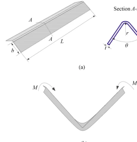
Figure 1.(a)The geometry of an undeformed creased strip and its cross-section and(b)localized fold at the middle of the creased strip by opposite-sense bending.
by comparing the finite element analyse (FEA) results and the experiment results adopted from Steffen et al. (2000) for the opposite-sense bending of a curved strip. Based on this, we studied the mechanical response of bending a creased thin strip. The influence of the geometry on the overall mechani-cal response was investigated. We also systematimechani-cally studied the transition from a creased strip to a curved strip. Further-more, the influence of on the mechanical behaviour of the creased strip was investigated.
2 Opposite-sense bending of creased thin strips
Opposite-sense bending of creased thin strips was studied in this paper. The crease region of the strip was treated as a cylindrical segment of a small radius, as shown in Fig. 1a. Thus the strip was simplified as the combination of two rect-angular facets of the same size and a curved crease. The key dimensions of the strip were the radius of crease curvature (r), the length of the strip (L), the width of the rectangular facet (b), the uniform thickness of the strip (t), and the initial opening angle (θ).
J. Liu et al.: Mechanical behaviour of a creased thin strip 93
Figure 2.(a)Curved strip with negative Gaussian curvature and subject to a moment coupleM >0 at both ends and the boundary condition (left), and the cross-section of the strip (right),(b)the mesh and the boundary conditions of the strip, and(c)the moment-rotation relationship obtained from the finite element modelling of curved strip as compared to that by Seffen et al. (2000).
3 Finite element analyses
3.1 Verification of the finite element model
The experimental result by Seffen et al. (2000) on the me-chanical response of bending a curved strip was employed in this paper to verify the finite element model. A curved strip adapted from Steffen et al. (2000) was analyzed (Fig. 2a), with dimensions and material properties listed in Table 1. In the model, the strip direction was set to be thezaxis Carte-sian coordinate and the y axis was vertically perpendicular to thezaxis. The displacement components of the strip ends were denoted asux,uy, anduz, respectively. The rotational
displacement components of the strip were denoted as βx,
βy, andβz, respectively. The boundary condition for
apply-ing a moment was defined byux=uy=uz=βy=βz=0
andβx=1 radian for the left end of the strip, andux=uy=
βy=βz=0 andβx= −1 radian for the other end.
There-fore, the degree-of-freedom inzdirection for the right end of the strip was released, which led to the asymmetrical bound-ary conditions. It should be noted that the curved strip in the work of Seffen et al. (2000) was initially doubly curved but this work focused on initially straight creased strips. In the finite element modelling by Abaqus standard, the
rota-tional displacement was implemented at the end of the strip. The shell was meshed by using 4-node reduced integration shell elements with five degrees of freedom per node (S4R5), making up 2736 elements (see Fig. 2b). Multiple point con-straints (MPC) were used to define the boundary conditions. The nodes at both ends of the strip were tied to an MPC node on the same plane at the middle of the arc by rigid beam el-ements to ensure their synergetic movel-ements, thus achieving pure bending, as shown in Fig. 2b. Dissipated energy frac-tion was used to enable the analysis to converge. The analysis method in Abaqus was static by considering geometric large deformation. The material was assumed to be linear elastic.
94 J. Liu et al.: Mechanical behaviour of a creased thin strip
Figure 3.Folding processes by finite element simulations for(a)flat strip,(b)curved strip, and(c)creased strip.
Table 1. Material properties and geometrical dimensions of the curved strip for FEA verification.
Designation Value
Young’s modulusE 131 000 N mm−2
Poisson’s ratioυ 0.3
Thicknesst 0.1 mm
LengthL 220 mm
Subtended angleα 2.39 rad
Transverse radiusRT 11.5 mm
Longitudinal radiusRL 1380 mm
3.2 FEA of folding creased thin strips
For the convenience of investigating purely the structural influence, the material for making the strips was kept un-changed in the FEA. Furthermore, to make sure that all the strips could be made of one same thin flat strip, their cross-sectional shapes shall be kept identical. In the FEA, at least four elements were used across the crease to assure the sim-ulation accuracy and quality. Assuming that all the strips had the same length and thickness, and the radius of the strip,
RL, was sufficiently large (the strips were approximately ini-tially straight), a geometrical constraint could be identified to define the relationship among the width of the rectangular facets (b), the radius of the crease segment (r) and the initial opening angle (θ)
(π−θ)r+2b=αRT (1)
whereRTwas the transverse radius of the curved strip,αwas the subtended angle of the curved strip. In this way, differ-ent types of strips could be made by using the same flat thin plate. For example, a set of geometrical parameters for cre-ating a creased strip with a fixed cross-sectional area could be identified according to Eq. (1), namely, b=13.70 mm,
r=0.1 mm, andθ=2.09 rad, which will be used in the fol-lowing finite element analyse to compare the mechanical be-haviour with those of flat and curved strips. For the flat strip, its cross-sectional area, thickness and length were the same with those of the curved and the creased strips. It should be noted that the values ofRLwere infinite for the creased and flat straight strips, whereRLwas the longitudinal radius.
J. Liu et al.: Mechanical behaviour of a creased thin strip 95
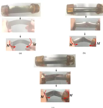
Figure 4.Folding processes of physical models for(a)flat strip,(b)curved strip, and(c)creased strip.
Figure 5. Moment-rotation relationship obtained from finite ele-ment modelling showing the comparison for the flat strip, the curved strip, and the creased strip.
0.3 mm). It should be noted that we have prepared and tested six specimens by using the vernier caliper, and the maxi-mum/minimum value for the thickness is 0.27 mm/0.31 mm. The opening angle for the creased strip was approximately 2.09 rad. We bended the flat, curved and folded thin metal strips using two hands, respectively. Each hand held the mixed polyamide resin and ethoxyline resin. We used the camera to capture three typical statuses during the bending process for each strip. Specifically, the first status is the orig-inal state, namely, before bending; the second status is when
βx=0.5 radian; the third status is whenβx=1 radian. The
96 J. Liu et al.: Mechanical behaviour of a creased thin strip
Figure 6.Moment-rotation relationship obtained from finite element modellings showing the influences of nondimensional geometrical parameters of the strips on the mechanical responses:(a)r / b,(b)L / b,(c)θ, and(d)t / b.
Figure 5 compared the moment-rotation curves of the three strips from the finite element simulations. In the bending pro-cess, flat strip showed a linear relationship between the mo-ment and the rotational angle with negligible momo-ment in the studying range as compared to the other two strips. The mo-ment of both the creased and curved strips rocketed up af-ter a very small rotation in the initial stage, peaking at val-ues above 300 N mm. With the occurrence of localized folds, the moment dropped instantly to much smaller values of be-low 50 N mm. Interestingly, at this stage, the moment of the curved strip would maintain at around 50 N mm. While the moment of creased strip would suddenly drop to a nega-tive moment value and steadily increase with the proceed-ing of rotation, then plateau at around 50 N mm. The sudden drop of the moment was attributed to the formation of local-ized folds. Unlike the curved strip, an even serious “snap-through” occurred during the bending of the creased strip. In the studied case, the creased strip had a smaller peak bend-ing moment than the curved one. Actually, the peak bendbend-ing moment was highly associated with the geometrical parame-ters of the strip. Thus, a detailed parametric study on creased strips was conducted and analyzed in the following section.
4 Parametric studies
Various finite element simulations were conducted to study the influence of the dimensionless geometrical parameters on the mechanical response of the creased strip, including radius of crease curvature to width ratio (r / b), strip length to width ratio (L / b), initial opening angle (θ), and strip thickness to width ratio (t / b). The value of the width of the rectangular facet (b) was fixed at 10 mm for all the analyses. The transi-tion from a creased strip to a curved strip was also systemat-ically investigated.
4.1 Radius of crease curvature to width ratio,r / b To investigate the influence ofr / b on the mechanical re-sponse of the creased strip, the length of the strip (L), the ini-tial opening angle (θ), and the uniform thickness of the strip (t) were fixed at 100 mm, 2.09 rad, 0.1 mm, respectively, i.e.,
J. Liu et al.: Mechanical behaviour of a creased thin strip 97
Figure 7.The transformation of localized folding from(a)single fold to(b)double folds.
were jointed directly. Figure 6a illustrated the mechanical re-sponses of creased strips of variousr / bvalues under bend-ing. Typical shapes as described previously were observed for all the strips. With the increase ofr / b, the peak moment increased. Furthermore, there was negligible difference in the moment whenr / b was smaller than 0.01. Further increase ofr / babove 0.01 resulted in seemingly larger increment of the moment. It should be pointed out that with the increase of r / b, i.e., larger radius of crease curvature, the so-called snap-through effect was weakened.
4.2 Strip length to width ratio,L / b
The influence ofL / bon the mechanical response of creased strips was investigated with its value ranging from 8 to 12 and the other parameters fixed at:r=0.1 mm,θ=2.09 rad,
t=0.1 mm (Fig. 6b). The results revealed that the smaller the value ofL / bwas (shorter strip), the larger the peak mo-ment would be. The peak momo-ment decreased from around 725 to around 487 N mm with L / b increased from 8 to 12. After the snap-through, all the obtained moment-rotation curves were almost identical, showing little influence ofL / b
on the mechanical response of creased strips at this stage. Noticeably,L / bhad little influence on the snap-through it-self, which was different from the influence ofr / b. We also found that, after the snap-through, the localized fold could be regarded as an elastic hinge with small bending stiffness for all the creased strips, as the moment-rotational response in this range is linear.
4.3 Initial opening angle,θ
The influence of the initial opening angle on the mechani-cal response of creased strips was studied when θ changed from 1.74 to 2.44 rad and the other parameters were fixed at: r=0.1 mm, L=100 mm, t=0.1 mm Fig. 6c plotted the moment-rotation curves of the studied strips of differ-ent opening angles. It could be seen that the peak momdiffer-ent
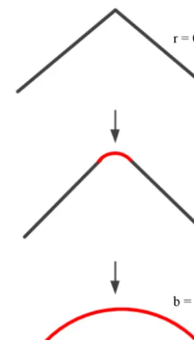
Figure 8.Schematic diagram of the transition from creased strip (r=0) to curved strip (b=0).
decreased from around 1161 round 487 N mm with increas-ing initial openincreas-ing angle from 1.74 to 2.44 rad. The initial opening angle had a small influence on the snap-through ef-fect. It should be noted that, when the initial opening angle increased to 2.44 rad, there was a sudden jump in the mo-ment in the bending process (highlighted in Fig. 6c as dashed rectangular). The sudden change in moment was due to the transition of localized fold from single mode (one localized fold, Fig. 7a) to double mode (two localized folds, Fig. 7b), showing a bifurcate phenomenon. The region between the two localized folds was relatively flat.
4.4 Strip thickness to width ratio,t / b
The influence oft / bon the mechanical response was also investigated when it varied from 0.01 to 0.05 and the other parameters were fixed at: r=0.1 mm, L=100 mm, θ=
2.09 rad. As shown in Fig. 6d, the strip thickness to width ratio had significant influence on the moment. The peak mo-ment increased from around 570 to around 9815 N mm when
t / b increased from 0.01 to 0.05, excessively larger than the moment values previously obtained. After snap-through, thicker strips showed much higher moments with no negative moment observed.
me-98 J. Liu et al.: Mechanical behaviour of a creased thin strip
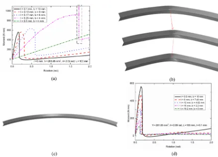
Figure 9.(a)Moment-rotation relationships obtained from finite element modelling showing the influence of the width of the rectangular facet (b) and the thickness of strip (t) on the mechanical response of the strip ofr=0 when the volume (V) and the length (L) of the strip were constant,(b)the travelling of the localized fold during bending for the creased strip whent=0.25 mm andb=4 mm,(c)deformed shape of the creased strip whent=0.50 mm andb=2 mm, and(d)moment-rotation relationships obtained from finite element modelling showing the influence of the radius of the crease curvature (r) and the width of the rectangular facet (b) on the mechanical response with fixed values of the thickness of strip (t), the initial opening angle (θ), the volume (V), and the length (L).
chanical response of strips during bending when the strip was transformed from creased-shape to curved-shape, we assumed that the mass/volume of the strip maintained un-changed. Therefore, the volume of the strip could be defined by
V =[2b+(π−θ)r]t L (2)
Firstly, we studied the influence of the width of the rectangu-lar facet (b), and the uniform thickness of the strip (t) on the overall mechanical behaviour of the strip ofr=0 by keep-ing the volume (V) and the length of the strip (L) constant, i.e.V =201.05 mm3,L=100 mm. Then we systematically investigated the transition from a creased strip to a curved strip by varying the radius of the crease curvature (r) and the width of the rectangular facet (b), with the fixed values of the initial opening angleθ, and the uniform thickness of the strip (t), the volume (V) and the length of the strip (L), e.g.,
θ=2.09 rad,t=0.1 mm,V =201.05 mm3,L=100 mm.
4.5.1 Strip with a line crease
Line crease occurred when the radius of the crease curva-ture (r) was zero (Fig. 8). Figure 9a compared the moment-rotation curves of strips with differentb andt values. The results showed that the moment-rotation curve shifted to the right when simultaneously increased the value oft and de-creased the value of b, with the peak moment increasing from around 563 N mm (t=0.1 mm,b=10 mm) to around 1181 N mm (t=0.25 mm, b=4 mm) in the studied range of rotation. For the ceased strip when b=4 mm and t=
J. Liu et al.: Mechanical behaviour of a creased thin strip 99
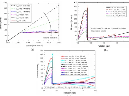
Figure 10.(a)Ideal true stress-strain curves of different materials with changing tangent moduli,(b) moment-rotation curves obtained from finite element modelling by using linear elastic material model, and(c)by using bilinear material model with the tangent modulus Etan=65 500 MPa.
witht=0.5 mm andb=2 mm, no peak moment was found in the studied rotation range as shown in Fig. 9a. Figure 9c indicated that localized fold had not occurred for this strip in the studied range. These findings showed that the width of the rectangular facet and the thickness together significantly influenced the overall mechanical behaviour of the creased strip when the radius of the crease curvature was zero, i.e., line crease.
4.5.2 Transition from a strip with a line crease to a curved strip
Figure 9d showed the mechanical responses for various thin strips when they were transforming from line strip to a curved strip. The thickness (t=0.1 mm), the initial opening angle (θ=2.09 rad), the volume (V =201.05 mm3) and the length (L=100 mm) of the strip were fixed. The radius of crease curvature (r) and the width of rectangular facet (b) varied. The moment decreases from 562.89 to 107.97 N mm, with the simultaneous increase of the radius of the crease curvature and decrease of the width of the rectangle facet.
We revealed that the moment of the strip varied significantly during the transition.
5 Transition from a linear elastic material to an elastic-perfectly plastic material
The application of origami always involves linear elastic ma-terials in numerical analyses. However, it shows increasing applications in structural applications such as energy absorp-tion structures, where material plasticity is often considered, e.g., aluminium or steel thin strips. Therefore, to reveal the influence of material properties on the mechanical response of creased strips, six types of materials considering elasticity and plasticity were applied as illustrated in Fig. 10a with dif-ferent tangent modulus (Etan). Other material coefficient in-cluded Young’s modulusE=131 000 MPa, Poisson’s ration
v=0.30 and yield stressσys=300 MPa. All the geometrical parameters were kept the same with those in Sect. 4.5.1 un-less otherwise noted, which were determined by Eq. (2) with the same volume. Typically,V =603.15 mm3,L=300 mm
100 J. Liu et al.: Mechanical behaviour of a creased thin strip
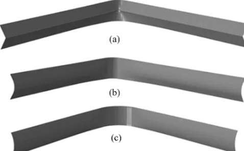
Figure 11. Typical deformed shapes of different strips in the fi-nite element modellings by using bilinear material model with the tangent modulus Etan=65 500 MPa:(a)strip withr=0 mm and b=10 mm,(b) strip withr=10 mm andb=4.82 mm, and (c)strip withr=19.2 mm,b=0 mm.
mechanical behaviour of the strip with various shapes from line to curved creases was extensively studied.
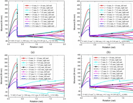
The moment-rotation curves for the linear elastic mate-rial, the bilinear material with the tangent modulus (Etan)= 65 500, 13 100, 6550, and 1310 MPa, and the elastic-perfectively plastic material was plotted in Figs. 10b–c and 12a–d, respectively. For all the curves, the moment became smaller when simultaneously increased the value of b and decreased the value ofrin the studied range of rotation, and the localised fold formed almost at the same rotational angle. Clear discrepancy was found at the stage after the formation of localised folds when the materials varying from elastic-ity to plasticelastic-ity. Noticeably, the two ends of the strips be-have differently for different materials. The moments of the two ends, i.e., left and right ends, of the thin strip behaved the same when linear elastic material was used. While, the moments of the two ends became evidently different when elasto-plastic materials were used, with the difference en-larged at smaller tangent modulus. It showed that the mo-ment of the left end strip was increasing while it decreased for the right end strip because of the influence of asymmetri-cal boundary conditions in the finite element modelling and the plastic deformation in the localised fold region. Part of the moment was consumed to generate kinetic energy to pro-duce plastic deformation when it was transited from left to right end when smaller tangent modulus was applied. When the tangent modulus became zero, i.e., elastic-perfectively plastic material, most of the moment was consumed, result-ing in the largest difference of moment at the two ends of the strip. It was interesting to find that some curves, i.e. when
r=5 mm,b=7.43 mm, the right end of the strip showed a decrease in moment after the snap-through as the rotation an-gle increased (see Fig. 10c), which might be due to the use of the non-linear material. It was also noteworthy that there
were several jumps in the curves, which might be caused by the use of the non-linear material as well. Figure 11a– c presented three typical deformed shapes for three thin strips (r=0 mm,b=10 mm;r=10 mm,b=4.82 mm; and
r=19.2 mm,b=0 mm) when the tangent modulus (Etan)= 65 500 MPa, which showed that the localised fold region be-came larger and more flat as simultaneously decreased the value ofband increased the value ofr.
6 Discussion
The introduction of a simple crease to a thin strip was numer-ically studied to reveal the influence of the crease on the over-all mechanical behaviour of the strip. Compared with curved and flat strips, the creased strip exhibited remarkably differ-ent mechanical behaviour. When a crease was introduced to a flat strip, we observed the magnitude of the peak moment in-creased by 100 times, demonstrating the dramatic influence of the simple crease on the mechanical behaviour of the strip. As revealed in the parametric studies, the moment-rotation curves of bending the creased strips showed typical three dis-tinct stages. Firstly, the moment increased to the peak value at a small rotation angle, then it dropped freely to show a snap-through procedure due to the formation of localized folds, which was followed by a final stage of smooth in-creasing in the moment to a stable value. The geometry of the creased strip could tremendously influence its mechan-ical response. The dimensionless parameterst / bandr / b
were found to have the greatest and the least influence on the mechanical response of the creased strips, respectively. We also found that the moment-rotation curves were very similar to each other after the formation of localized folds for strips with various values ofL / b, andθ. Furthermore, the local-ized fold could trigger two different folds on the same strip if the initial opening angle was sufficiently large, e.g., 2.44 rad (Fig. 7). When the strip transformed from line-creased struc-ture to curved strucstruc-ture, the change in geometrical parame-tersrandbsignificantly influenced the moment of the strip. It should be noted that not all the strips formed the localized folds. For example, the creased strip witht=0.50 mm and
b=2 mm (Fig. 9c) had no localized fold, which is similar to the flat strip as shown in Fig. 3a.
J. Liu et al.: Mechanical behaviour of a creased thin strip 101
Figure 12.Moment-rotation curves obtained from finite element modelling by using bilinear material model with different tangent modu-lus(a)Etan=13 100 MPa,(b)Etan=6550 MPa,(c)Etan=1310 MPa, and(d)Etan=0 MPa (elastic-perfectly plastic material).
7 Conclusions
In this paper the mechanical behaviour of a creased thin strip under opposite-sense bending was studied via finite el-ement modelling which was verified by physical models. The effects of the dimensionless parameters, includingr / b,
L / b,θ, and t / b, on the overall mechanical behaviour of the creased strip were systematically investigated. The re-sults revealed that the introduction of a simple crease to the thin strip could significantly alter the flexural performance of the strip. The uniform thickness and the radius of the creased segment had the greatest and the least influence on the mechanical behaviour of the creased strip, respectively. The investigation of the transition from a creased strip to a curved strip uncovered the tremendous influence of the geo-metrical parameters on the overall mechanical behaviour of the strip. We also showed that the material properties could play a key role in the bending of the creased strip. Further-more, deformed shapes of the creased strips from the finite element simulations agreed well with those of the physical models made from thin metal strips. The findings from this study provide useful information for designing origami
struc-tures using creased thin strips. Specifically, they can guide engineers to design self-folding structures, energy absorbing structures and others.
Data availability. The data underlying this article are not available by agreement with our partners to protect their commercial confi-dentiality.
Competing interests. The authors declare that they have no con-flict of interest.
102 J. Liu et al.: Mechanical behaviour of a creased thin strip
Edited by: Guangbo Hao
Reviewed by: Shuang Xu and one anonymous referee
References
Chen, Y., Peng, R., and You, Z.: Origami of thick panels, Science, 349, 396–400, 2015.
Couturier, E., Dumais, J., Cerda, E., and Katifori, E.: Folding of an opened spherical shell, Soft Matter, 9, 8359–8367, 2013. Delimont, I. L., Magleby, S. P., and Howell, L. L.: Evaluating
compliant hinge geometries for origami-inspired mechanisms, J. Mech. Robot., 7, 011009, https://doi.org/10.1115/1.4029325, 2015.
Dias, M. A. and Audoly, B.: A non-linear rod model for folded elas-tic strips, J. Mech. Phys. Solids, 62, 57–80, 2014.
Dias, M. A., Dudte, L. H., Mahadevan, L., and Santangelo, C. D.: Geometric mechanics of curved crease origami, Phys. Rev. Lett., 109, 114301, https://doi.org/10.1103/PhysRevLett.109.114301, 2012.
Filipov, E. T., Tachi, T., and Paulino, G. H.: Origami tubes assem-bled into stiff, yet reconfigurable structures and metamaterials, P. Natl. Acad. Sci. USA, 112, 12321–12326, 2015.
Francis, K. C., Blanch, J. E., Magleby, S. P., and Howell, L. L.: Origami-like creases in sheet materials for compliant mechanism design, Mech. Sci., 4, 371–380, 2013.
Gething, M. J. and Sambrook, J.: Protein folding in the cell, Nature, 355, 33–45, 1992.
Hanna, B. H., Lund, J. M., Lang, R. J., Magleby, S. P., and Howell, L. L.: Waterbomb base: a symmetric single-vertex bistable origami mechanism, Smart Mater. Struct., 23, 094009, https://doi.org/10.1088/0964-1726/23/9/094009, 2014.
Jayaram, K. and Full, R. J.: Cockroaches traverse crevices, crawl rapidly in confined spaces, and inspire a soft, legged robot, P. Natl. Acad. Sci. USA, 113, E950–E957, 2016.
Lechenault, F., Thiria, B., and Bedia, M. A.: Mechanical re-sponse of a creased sheet, Phys. Rev. Lett., 112, 244301, https://doi.org/10.1103/PhysRevLett.112.244301, 2014. Lin, S., Xie, Y. M., Li, Q., Huang, X., and Zhou, S.: A kirigami
approach to forming a synthetic buckliball, Sci. Rep., 6, 33016, https://doi.org/10.1038/srep33016, 2016.
Na, J. H., Evans, A. A., Bae, J., Chiappelli, M. C., Santangelo, C. D., Lang, R. J., Thomas, C. H., and Hayward, R. C.: Program-ming reversibly self-folding origami with micropatterned photo-crosslinkable polymer trilayers, Adv. Mater., 27, 79–85, 2015.
Overvelde, J. T., Weaver, J. C., Hoberman, C., and Bertoldi, K.: Ra-tional design of reconfigurable prismatic architected materials, Nature, 541, 347–352, 2017.
Schenk, M. and Guest, S. D.: Origami folding: A structural engi-neering approach, In Origami 5: Fifth International Meeting of Origami Science, Mathematics, and Education CRC Press, Boca Raton, FL, 291–304, 2011.
Soykasap Ö.: Analysis of tape spring hinges, Int. J. Mech. Sci., 49, 853–860, 2007.
Seffen, K. A. and Pellegrino, S.: Deployment dynamics of tape springs, Proc. R. Soc. Lon. Ser.-A, 455, 1003–1048, 1999. Seffen, K. A., You, Z., and Pellegrino, S.: Folding and deployment
of curved tape springs, Int. J. Mech. Sci., 42, 2055–2073, 2000. Walker, M. G. and Seffen, K. A.: Flexural mechanics of creases
in thin metallic strips, Proceedings of the IASS Annual Sym-posium, Spatial Structures in the 21st Century, 26–30 Septem-ber 2016, Tokyo, Japan, 2016.
Walker, S. J. I. and Aglietti, G. S.: Experimental investigation of tape springs folded in three dimensions, AIAA J., 44, 151–159, 2006.
Yang, H., Liu, R., Wang, Y., Deng, Z., and Guo, H.: Experiment and multiobjective optimization design of tape-spring hinges, Struct. Multidiscip. O., 51, 1373–1384, 2015.
Yang, K., Xu, S., Shen, J., Zhou, S., and Xie, Y. M.: Energy ab-sorption of thin-walled tubes with pre-folded origami patterns: numerical simulation and experimental verification, Thin Wall. Struct., 103, 33–44, 2016.
Yang, K., Xu, S., Shen, J., Zhou, S., and Xie, Y. M.: Design of dim-pled tubular structures for energy absorption, Thin Wall. Struct., 112, 31–40, 2017.
Yasuda, H. and Yang, J.: Reentrant origami-based metamaterials with negative Poisson’s ratio and bistability, Phys. Rev. Lett., 114, 185502, https://doi.org/10.1103/PhysRevLett.114.185502, 2015.