229 | P a g e
RECOGNITION OF INDIAN SIGN LANGUAGE
STATIC GESTURES USING CASCADING OF
PARAMETRIC AND NON-PARAMETRIC MODELING
APPROACH FOR SEGMENTATION
Komal Sheth
1, Prof.P.R.Futane
2 1Computer Engineering Department, SCOE, Pune University(India)
2HOD, Computer Engineering Department, SCOE, Pune University(India)
ABSTRACT
Sign language is the most natural mode of communication for dumb-mute people. Considerable amount of population in India is suffering from hearing impairment. India is at the initial stage in developing a sign language based applications. In this paper, a methodology is proposed that recognizes static gestures from the native ISL. The system works on a vision based setup and also it maintains the naturalness while performing the sign. A hybrid segmentation approach comprising Gaussian Mixture Modeling (GMM) and look-Up Table techniques is applied to static signs in complex backgrounds. Angular Radial Partitioning (ARP), a Shape based descriptor, is used to extract the features of the KVOPs. L1 norm or Manhattan Distance measure is used to recognize the gesture. The results of the approach are promising and it overcomes some of the limitations of the approaches from the literature.
Keywords:
ARP, ISL, Foreground Detection, Feature Extraction, SLR.
I. INTRODUCTION
The sign language used in India is called as Indian Sign Language (ISL). ISL is not genetically related to any
other Sign Language. Over the past decade more number of re-searchers all over the world is working on the
Human-Computer Interaction (HCI) to build a robust Sign Language Recognition System. Fig. 1 shows the
recent trends in this area.
230 | P a g e
Hand configuration as defined by the flex angles of the fingers, Palm orientation and Handmovement as
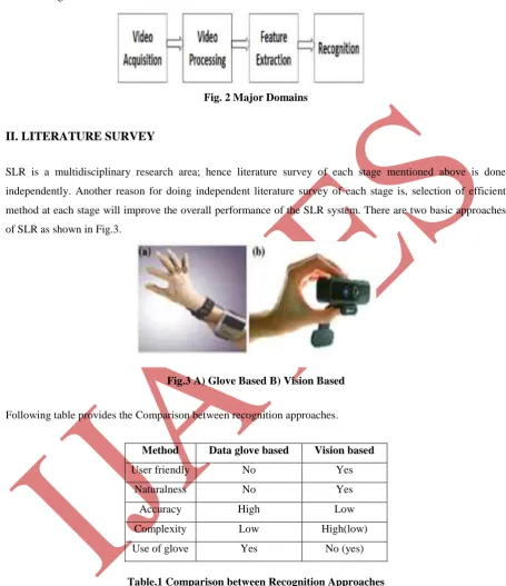
defined by the motion of the palm in space. Major steps in the vision based Sign Language recognition are
shown in Fig.2
Fig. 2 Major Domains
II. LITERATURE SURVEY
SLR is a multidisciplinary research area; hence literature survey of each stage mentioned above is done
independently. Another reason for doing independent literature survey of each stage is, selection of efficient
method at each stage will improve the overall performance of the SLR system. There are two basic approaches
of SLR as shown in Fig.3.
Fig.3 A) Glove Based B) Vision Based
Following table provides the Comparison between recognition approaches.
Method Data glove based Vision based
User friendly No Yes
Naturalness No Yes
Accuracy High Low
Complexity Low High(low)
Use of glove Yes No (yes)
Table.1 Comparison between Recognition Approaches
Some of the vision based approaches also make use of the colored gloves, as used in [7]. But this also restricts
the naturalness of the SLR. In order to overcome this, skin color based approach limitations vision based SLR
was developed. Using skin color cue has some advantages; it allows faster processing and is robust to resolution
changes. But use of skin color is plagued by some factors such as Illumination, Camera characteristics,
Ethnicity. [6].The skin representation and skin segmentation tree diagram can be found in [21]. Explicitly
231 | P a g e
space. This method makes use of the explicitly declared decision boundaries for the components of the colorspace in order to detect the skin. However, representation of the skin color is affected considerably with
variation of illumination, ethnicity, camera used for capturing the images etc. Skin colors of individuals cluster
differently in the color space. This technique is used in [5] [3]. In order to overcome this challenge using
combination of three color spaces is used [20]. The accuracy is found to improve at the cost of computational
time. However, it gives high true positive rate at expense of high false positive rate. Non-parametric modelling
technique like histogram based method is used in [8]. The paper concludes that the Look-Up Table (LUT)
approach of skin modelling is computationally efficient. This approach was also adopted by [9], [11]. Bayesian
method is used in [10], [11]. However, Non-parametric models lack the ability to interpolate the skin
distribution, require large training set for better accuracy. The performance of the model is affected by the
degree of skin and non-skin overlap also these methods require high storage. Parametric modelling techniques
include, Single Gaussian Modelling (SGM) and Gaussian Mixture Modelling (GMM). SGM approach is used in
[12]. However, these methods are computationally expensive because of the conventional EM algorithm used
for parameter estimation. After the skin segmentation, the features of an object of interest are extracted to
express it in a compact form. Commonly used feature extraction techniques are Physical Features [13], Principal
Component Analysis (PCA) [15], Discrete Cosine Transform (DCT) [14] and Angular Radial Partitioning
(ARP). Advantages and limitations of these techniques are provided in [22]. The last module is recognition,
some of the widely used techniques are Neural Networks [3],[14], FSM [16] and Hidden Markov models
(HMM) [3], [1].
III. METHODOLOGY
The signs from ISL that are used for the experiment and also the results obtained from each module are
presented in this section. Signs that are used for the experiment are given below in table 2. In the present work
the self created database is used. The signs are loaded by 2 signers in varied environments.
232 | P a g e
3.1 Video Acquisition:The Video is captured using inbuilt web-cam with following constraints;
1. Signer should wear dark coloured full sleeve shirt
2. Illumination should be constant.
3. Signer should maintain approximately constant distance from the capturing source.
4. During the acquisition exposure to other body parts to be avoided.
5. The background can be complex.
The figure 4 shows the set up used for the video acquisition.
Fig.4 Video Acquisition Set-Up
The web cam captures the video and converts it into size 640 X 480; video is acquired in RGB format. Overall 3
videos are recorded for particular sign for the purpose of database creation and 7 videos for a particular sign are
recorded for testing purpose.
3.2 Video Segmentation
The next step is to detect the hand accurately. The accuracy of any system and the computational time are
inversely proportional parameters. Hence in the proposed approach segmentation algorithms are used in such a
way that it would reduce the total computational time without sacrificing the detection accuracy. For hand
segmentation cascading of two methods is adopted which includes GMM for foreground detection and LUT for
skin detection. The video acquired is of higher resolution. The GMM and LUT algorithms consider every pixel
from the frame for processing, hence to reduce the computational time the all frames of the video are resized to
80 X 60 pixels. This division of process makes the segmentation accurate even in complex background as the
background gets filtered out in the first process. The experimental parameters used for these two processes are
discussed in this section.
3.2.1 Foreground Detection
GMM is used for the foreground detection. It is a parametric skin modelling technique in which the parameters
of the Gaussian are updated with conventional GMM algorithm. The algorithm can handle complex background
and hence even though it is computationally expensive, it is used in the segmentation. The difference between
Foreground Detection stage of the proposed algorithm and the one given by [6] is that, in this case few initial
233 | P a g e
camera till the background learning is over. This is done in order to learn the background efficiently and it givesmore accurate foreground detection results. Table 3 gives the details of the parameters used for Foreground
Detection. The parameters that are mentioned in the table are taken from [3].
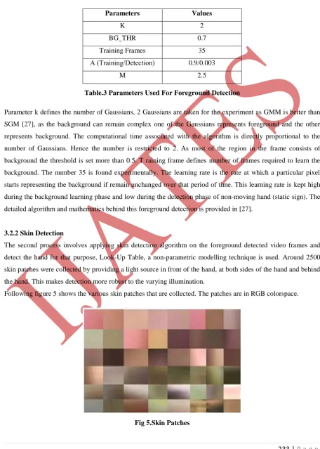
Parameters Values
K 2
BG_THR 0.7
Training Frames 35
Α (Training/Detection) 0.9/0.003
M 2.5
Table.3 Parameters Used For Foreground Detection
Parameter k defines the number of Gaussians, 2 Gaussians are taken for the experiment as GMM is better than
SGM [27], as the background can remain complex one of the Gaussians represents foreground and the other
represents background. The computational time associated with the algorithm is directly proportional to the
number of Gaussians. Hence the number is restricted to 2. As most of the region in the frame consists of
background the threshold is set more than 0.5. T raining frame defines number of frames required to learn the
background. The number 35 is found experimentally. The learning rate is the rate at which a particular pixel
starts representing the background if remain unchanged over that period of time. This learning rate is kept high
during the background learning phase and low during the detection phase of non-moving hand (static sign). The
detailed algorithm and mathematics behind this foreground detection is provided in [27].
3.2.2 Skin Detection
The second process involves applying skin detection algorithm on the foreground detected video frames and
detect the hand for that purpose, Look-Up Table, a non-parametric modelling technique is used. Around 2500
skin patches were collected by providing a light source in front of the hand, at both sides of the hand and behind
the hand. This makes detection more robust to the varying illumination.
Following figure 5 shows the various skin patches that are collected. The patches are in RGB colorspace.
234 | P a g e
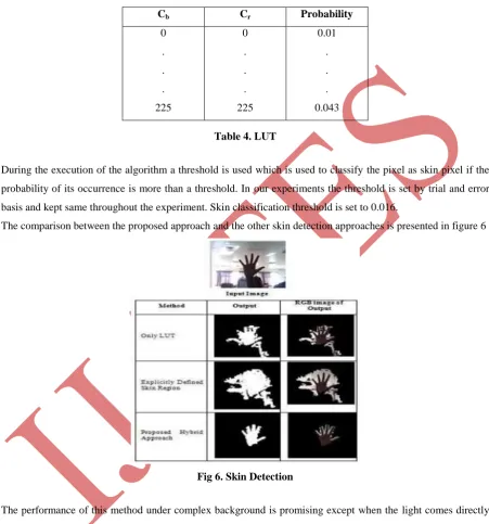
The actual skin tone varies a lot with the illumination and position of the hand. For creating a LUT from theepatches the images in RGB color space are converted to CbCr color space in which the skin and non-skin
overlap is reduced. A table is generated by considering every color vector of CbCr, i.e from (0 0) to (255 255).
Probability of each color vector is found and LUT is generated. A sample LUT is shown by table 4
Cb Cr Probability
0
.
.
.
225
0
.
.
.
225
0.01
.
.
.
0.043
Table 4. LUT
During the execution of the algorithm a threshold is used which is used to classify the pixel as skin pixel if the
probability of its occurrence is more than a threshold. In our experiments the threshold is set by trial and error
basis and kept same throughout the experiment. Skin classification threshold is set to 0.016.
The comparison between the proposed approach and the other skin detection approaches is presented in figure 6
Fig 6. Skin Detection
The performance of this method under complex background is promising except when the light comes directly
onto the gesturing hand. As the foreground detection works on the difference between the background and a
foreground pixel, when gesturing hand comes in front of a large skin coloured object, then it may not give
accurate results. The method takes more time in segmentation of the hand than the methods discussed in the
235 | P a g e
3.3 Feature Extraction3.3.1 Key Video Object Plane
Typically, key VOPs should be selected such that they reflect significant changes in the shape, color, and texture
content of a video object. Using the shape content of a video object for key VOP selection has many advantages
over using the color and/or texture content. Before applying the feature extraction technique gesture
summarization is performed by abstracting the KVOPs (Key Video Object Planes) from the input sign. More
de-tails about the VOPs and KVOPs are presented in [13]. KVOPs differ significantly from each other. These
KVOPs are found with help of Hausdorff Distance measure [14] Pseudo code of the KVOP generation is similar
to that presented in [17]. In short, the first VOP is declared as KVOP and then subsequent VOPs are compared
with the KVOP; till the Hausdorff Distance is greater than threshold. Once the distance be-comes greater than
threshold that VOP becomes second KVOP and process continues till the end of video sequence. The formula
for calculating threshold is given below. The details of the formula are provided in [18].
thr = (min(M1, M2)2 + min(N1 , N2)2)
Where,
λ: a constant which is kept same during training and testing
M1, M2: width of the VOP candidate
N1, N2: height of the VOP candidate
The total number of KVOPs for a particular gesture depends upon the value of ;
Greater the value of lesser will be the number of KVOPs.
The Hausdorff distance measure can also be used to measure the similarity between two shapes. It is defined as
the maxmin function between two sets of points as follows
h(A, B) = max{min{d(a, b)}}
Where, A and B are the points of the sets A and B, respectively, and d(a,b) is the Euclidean distance between
these points. More specifically, the Hausdorff distance between the sets of points A and B is the maximum
distance of the points in set to the nearest point in set B. The Hausdorff distance is not symmetric, i.e.,h(A,B)
may not be equal to h(B,A) Therefore, a more general definition of the Hausdorff distance is given by
H (A, B) = max{h(a, b), h(b, a)}
Here, (A,B) and h(B,A) are the Hausdorff distances from A to B, and from B to A, respectively.
As in case of static gestures there is no change in hand position or no hand movement is included we get a single
KVOP.
3.3.2 Angular Radial Partitioning
The main objective of ARP is to transform the image data into a new structure that supports measurement of the
similarity between images in an effective, easy and efficient manner with emphasis on capturing scale and
rotation invariant properties. The edge map of an image carries the solid structure of the image.
This module represents a sign in a compact form, thus reduces the storage requirements.
The features that are scale invariant, translation invariant and rotation invariant are of the utmost importance. If
such features are extracted then a sign can be performed by any signer at any location in the given frame and
236 | P a g e
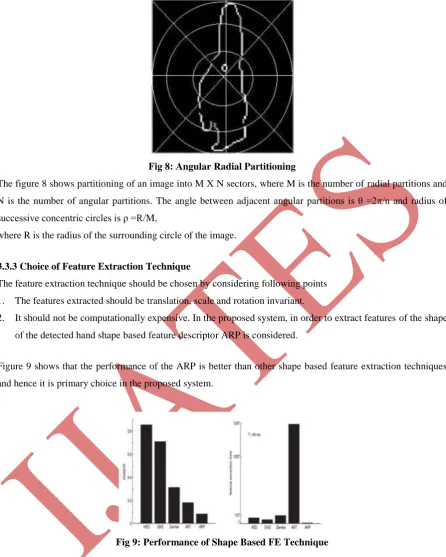
Fig 8: Angular Radial PartitioningThe figure 8 shows partitioning of an image into M X N sectors, where M is the number of radial partitions and
N is the number of angular partitions. The angle between adjacent angular partitions is θ =2π/n and radius of
successive concentric circles is ρ =R/M,
where R is the radius of the surrounding circle of the image.
3.3.3 Choice of Feature Extraction Technique
The feature extraction technique should be chosen by considering following points
1. The features extracted should be translation, scale and rotation invariant.
2. It should not be computationally expensive. In the proposed system, in order to extract features of the shape
of the detected hand shape based feature descriptor ARP is considered.
Figure 9 shows that the performance of the ARP is better than other shape based feature extraction techniques
and hence it is primary choice in the proposed system.
Fig 9: Performance of Shape Based FE Technique
The rotation invariance permitted by the proposed system is shown in the following figure10. Hand rotation
237 | P a g e
Fig10: Rotation InvarianceThe Translation invariance permitted by the system is given below. It can be seen from the figure 11, the same
sign is performed by 2 different signers by placing hand at slightly different location. Still there is only a
marginal variation in the final edge image formed. This invariance is achieved by finding the bounding box
around VOP and extracting only that part of the image and placing it in the centre of the frame.
Fig 11: Transition Invariance Fig 12: Scale Invariance
Scale invariance permitted by the system is given in figure 12. 5 radial partitions are considered. Around 10-15
pixels of scale invariance are permitted by the system. These edge images are used for the further feature
extraction process. Modified Angular Radial Partitioning (ARP) is used for feature extraction. This is a shape
descriptor. More details about its algorithm and advantages are given in [4], [18]. The modification made in the
proposed approach is, a feature vector is generated only by considering the skin pixels present in each sector.
1-D FFT is not applied as proposed originally by [4].
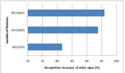
3.3.4 Choice Of The Size Of Features
It is observed in the figure 5.12 that the performance of the system improves considerably when feature vector
with size 5X18 is considered. The computational time variation for extracting features is found negligible when
different radial and angular partitions are considered. Hence in order to improve the performance of the system,
Figure 13 Comparison of results obtained using Different sizes of ARP features feature vector combination with
238 | P a g e
Fig 13: Comparison of Results Obtained Using Different Sizes of ARP FeaturesIV. RESULTS
The database of features of the signs is created by performing a particular sign 3 times. The sign is performed by
2 different signers under different backgrounds.
In static module the methods used for the recognition are as follows:
Video Acquisition: 60 frames in complex background.
Video Segmentation: GMM for background removal and LUT for skin detection.
Feature Extraction: ARP with 18 angular partitions and 5 radial partitions i.e. total 90 features.
Recognition: features are compared using Manhattan distance. The Results of the static signs are given in
table
Sign Total Train Wrong Accuracy
Friend 10 3 0 100%
Mirror 10 3 1 85.71%
Oath 10 3 0 100%
Short 10 3 0 100%
Cartridge 10 3 0 100%
High 10 3 0 100%
Up 10 3 1 85.71%
Table: Result of Static Signs
During the experiment 2 signs are misclassified. Figure 5.13 provides the VOPs of the misclassified signs. There
exists a close resemblance between signs Friend and Up, Friend and Mirror also in Short and Oath. Higher
number of angular and radial partitions in ARP is responsible in capturing this difference correctly. Hence the
recognition accuracy of static sign is 95.91%
V. CONCLUSION
The video segmentation is hybrid for static signs as they involve complex background. In case of segmentation
of static signs a hybrid approach involving GMM and LUT is adopted LUT method is more accurate than
239 | P a g e
Table for every color vector corresponding to each pixel. For explicitly defined skin region the computationaltime is lesser as the colorvector is compared only with 4 predefined values representing the range. The proposed
hybrid approach performs better in complex background than other approaches presented in the literature. Use
of ARP for feature extraction makes the extraction and retrieval much faster than the techniques presented in the
literature. ARP provides rotation and scale invariance to the extracted features upto certain degree. The use of
boundingboxes makes the features translation invariant and hence can accommodate spatial variance while
per-forming the sign. In the present work 7 different static signs. The signs are performed by 2 different signers.
The present approach overcomes the imitations of the approach presented in literature in following aspects, by
considering both uniform and non uniform background during video acquisition. The results of the proposed
method are promising as a marginal improvement in the recognition accuracy is also observed. The recognition
accuracy of the proposed system is, 95.91% for static signs.
ACKNOWLEDGMENTS
The authors wish to thank to Mr. Shirin Dora for providing research papers as and when needed, also special
thanks to Mr. Nitish Gadgil and Mr. Abhishek Badki for providing valuable suggestions throughout the
research work.
REFERENCE
[1] Kenny Morrison, Stephen J. McKenna; An Experimental Comparison of Trajectory-Based and
History-Based Representation for Gesture Recog-nition; In Proceedings of the International Gesture
Workshop,2004.
[2] Muhammad Yousuf Bin Azhar , Israr Ahmed, Sameer Rafiq, Sul eman Mumtaz Ali Mehmood Usman,
Razi Ur Rehman; Boltoy Haath- Palistani Sign Language Recognition; Department Of Computer
Engineering; Sir Syed University
[3] Anirudh Garg; Converting American Sign Language To Voice Using RBFNN; Masters Thesis, Computer
Science, Faculty of San Diego State University, Summer 2012.
[4] M.K. Bhuyan, P.K. Bora, and D. Ghosh; Trajectory Guided Recognition of Hand Gestures having only
Global Motions; International Journal of Electrical and Computer Engineering, vol.3, no..44, 2008.
[5] Swathi Rajashekar; Composite Feature-Based Face Detection Using Skin Color Modeling and SVM
Classification; Masters Thesis, Comp uter Science, Utah State University, 2012.
[6] P. Kakumanu, S. Makrogiannis, N. Bourbakis; Asurvey of skin-color modeling and detection methods;
Elsevier, The journal of the pattern recognition society, 40 ,1106 1122, 2007.
[7] Archana S. Ghotkar,Gajanan K. Kharate; “Hand Segmentat ion Tech-niques to Hand Gesture Recognition
for Natural Human Computer In-teraction”;International Journal of Human Computer Inter action (IJHCI),
Volume (3) : Issue (1) : 2012
[8] Q. Liu, G. Peng, A Robust Skin Color Based Face Detection Algorithm, 2nd International Asia
Conference on Informatics in Control, Automation and Robotics, 2010.
[9] R. Porle, A. Chekima, F. Wong, and G. Sainarayanan, Performance of Histogram-Based Skin Colour
Segmentation for Arms Detection in Human Motion Analysis Application, International Journal of
240 | P a g e
[10] S. Phung, A. Bouzerdoum, and D. Chai, Skin Segmentation Using Color and Edge Information,Proceedings Seventh International Symposium on Signal Processing and Its Applications, vol:1, 2003.
[11] B. Zarit, B. Super and F. Quek, Comparison of Five Color Models in Skin Pixel Classification,
Proceedings. International W orkshop on Recognition, Analysis, and Tracking of Faces and Gestures in
Real-Time Systems, 1999..
[12] J. Rekha, J. Bhattacharya and S. Majumder, Shape. Texture and Local Movement Hand Gesture Features
for Indian Sign Language Recognition, 3rd International Conference on trendz in Information Sciences
and Computing (TISC), 2011.
[13] Xingyan Li; Vision Based Gesture Recognition System With High Ac-curacy; Department of Computer
Science, The University of Tennessee, Knoxville, TN 37996-3450, 2005.
[14] Deepika Tewari, Sanjay Kumar Srivastava; A Visual Recognition of Static Hand Gestures in Indian Sign
Language based on Kohonen Self-Organizing Map Algorithm ; International Journal of Engineering and
Advanced Technology (IJEAT), ISSN: 2249 8958, Volume-2, Issue-2, December 2012
[15] Henrik Birk, Thomas Baltzer Moeslund; Recognizing Gestures From the Hand Alphabet Using
PrincipalComponent Analysis; Masters Thesis, Laboratory of Image Analysis, Aalborg University,
Denmark, October 1996
[16] M.K. Bhuyan, FSM-based Recognition of Dynamic Hand Gestures via Gesture Summarization using Key
Video Object Planes, International Journal of Computer and Communication Engineering 6, 2012.
[17] A. Chalechale, A. Mertins and G. Naghdy, Edge image description using angular radial partitioning, IEE
Proc.-Vis. Image Signal Process., Vol. 151, No. 2, April 2004.
[18] J. Bernal, F. Vilarino, J. Sanchez; Feature Detectors and Feature Descrip-tors:WhereWe Are Now;
Technical Report 154, Computer Vision Center & Computer Science Department, Universitat Autonoma
de Barcelona, 2010.
[19] Daniel Huttenlocher, Gregory Klandarman and Wlliam Rucklidge, Comparing Images using Hausdorff
Distance,IEEE transaction on pattern analysis and machine intelligence, vol.15, no.9, Sept. 1993.
[20] S. Singh, D. S. Chauhan, M. Vatsa and R. Singh, A Robust Skin Color Based Face Detection Algorithm,
Tamkang Journal of Science and Engineering, Vol. 6, No. 4, pp. 227-234, 2003.
[21] Komal Sheth, Nitish Gadgil and P.R. Futane, A Hybrid Hand Detection Algorithm for Human Computer
Interaction using Skin Color & Motion Cues , IJCA, Volume 84 No 2, December 2013.
[22] Komal Sheth, Nitish Gadgil and P.R. Futane, A Survey of Gesture Recognition Systems for Indian Sign
Language Recognition, International Journal of Engineering and Advanced Technology (IJEAT), Vol.2,