THE EFFECT OF JET GROUTING ON THE
BEHAVIOR OF STRIP FOOTING ADJACENT TO
SLOPE CREST
Ahmed M. Tuhami
1, Ahmed A. Mohamed
2.
1
Associate Professor of Soil Mechanics and Foundations, Civil Eng. Dept. Bany Suafe University,
Egypt, currently seconded to Umm Alqura university, (Saudia Arabia)
2
AssistantProfessor of Soil Mechanics and Foundations, Civil Eng. Dept. AL-Azhar University,
Qena, (Egypt)
ABSTRACT
This paper studies the behavior of strip footing adjacent to slope crest and the effect of jet grouting under the
footing. This problem is investigated numerically in the present study. Two dimensional plane strain program
PLAXIS is used in this study. 15 nodes triangular element is used to idealize soil with Hardening soil model.
Five nodes isoperimetric beam element is used to idealize stripe footing. Interface element is used to represent
the contact between beam element and soil. Two parameters were studied, the first is the foundation depth and
the second is the Stripe footing distance from the slope crest. Settlement and horizontal displacement of strip
footing were obtained and studied from the analyzed finite element model results. The reduction influence of jet
groutingon footing displacement were studied and investigated. The results indicate that the inclusion of jet
grouting under strip footing adjacent to slope crest has significant effect in improving the response of the strip
footing and the slope.
Keywords: Strip footing, Jet grouting, Slope, PLAXIS, Relative distance.
I. INTRODUCTION
The bearing capacity of the foundation is a primary concern in the field of foundation engineering. The foundation should transfer theself weight of the structure and the applied loads to the soil safely and economically. Quite often, structures are built on or near a slope. This is due to land limitation, such as for bridges or for architectural purposes. The ultimate bearing capacity of the foundations is significantly affected by the presence of the slope. Design of foundations under these conditions is Complex due to expected deformation and rotation of nearby slope .In these cases design requirements stipulate that in additional for the foundations to transfer the load safely to the underlain soil strata but also the stability of the slope after incorporating the foundations load must remain intact. Occasionally engineers are required to determine the location and depth of foundations to be built on or near slope. Design of safe foundation in this case inquires determining the minimum distance and foundation depth as a function of slope geotechnical conditions.
years, the subject of stabilizing earth slope has become one of the most interesting areas for scientific research and attracted a great deal of attention.
Typical methods of enhancing slope stabilityinclude modifying the slope surface geometry, chemical grouting, using soil reinforcement, or installing continuous or discrete retaining structures such as diaphragm walls, sheet pile walls or piles, (M. El Sawwaf 2009).
Injection methods are attractive because they can be implemented at relatively low cost. Their drawback is that it is difficult to quantify the beneficial effects. In addition, when fluids are injected, the short-term effect may be to make the slope less stable. The beneficial effects may be achieved only later, when the injected material has hardened or has reacted with the soil to alter its properties. ( J. M. Duncan and S. G. Wright 2005)
Lime piles are drilled holes filled with lime. Lime slurry piles are drilled holes filled with slurry of lime and water. Rogers and Glendinning (1993, 1994, and 1997) reviewed the use of lime piles and lime slurry piles to stabilize slopes, and the mechanisms through which they improve soil strength and stability.
Handy and Williams (1967) described the use of quicklime placed in drilled holes to stabilize a landslide in DesMoines, Iowa. Six-inch-diameter holes were drilledthrough a compacted silty clay fill, down to the surfaceof the underlying shale, where the fill was sliding onthe top of the shale. About 50 lb of quicklime wasplaced in each hole, filling the bottom 3 ft. Water wasthen added to hydrate the lime, and the holes werebackfilled to the surface with soil. Holes were drilled5 ft apart, stabilizing an area 200 ft by 125 ft usingabout 20 tons of quicklime. Physical and chemical testson the treated soil showed that the lime was reactingwith and strengthening the silty clay fill. Movement ofthe slide essentially stopped within three months aftertreatment, while movements continued in adjacent untreatedareas.
Stabilizing landslides by injecting cement grout hasbeen used extensively on both American (Smith andPeck, 1955) and British railroads (Purbrick and Ayres,1956; Ayres, 1959, 1961, 1985). Typical practice involvesdriving grout points about 5 ft apart in rowsparallel to the track, the rows being about 15 ft apart.The tips of the grout points are driven about 3 ft belowthe estimated depth of the rupture surface, and about50 ft3 of grout is injected through each point. Quitehigh grouting pressures are used for the shallow depthsinvolved: For grouting only 15 ft beneath the surface, a grouting pressure of 75 psi might be used for injectionof the first 10 ft3, subsequently dropping to 20 psi.
Results of laboratory model tests and numerical study on the behavior of a strip footing withstructural skirts adjacent to a sand slope are presented and investigated by (W. R. Azzam and A. Farouk (2010))
S.V. Anil Kumarand K. Ilamparuthi (2009) concluded that load-settlement behavior and bearing capacity can be improved by inclusion of geosynthetic reinforcement underthe footing. Further the bearing capacity decreases with increase in slope angle and decrease in edge distance both inreinforced and unreinforced slopes.
II. OBJECTIVES
The main objective of the present studyis to investigate different aspects of the behavior of slopes in soil and the response of structures located near these slopes. The main objectives for this research are:-
i. Establishing an analytical model to represent realistic behavior for the slope and theadjacent strip footing. ii. Studying the effect of the parameters affecting on the behavior of the chosen modelsuch as distance between
the building and slope crest and building foundation depth.
III. NUMERICAL MODELING AND SELECTION OF PARAMETERS
Soil code Finite Element Program Plaxis 7.2 was used in numerical modeling. Plaxis program was further applied to analysis different investigated parameters using prototype dimensions.
3.1 Material Model of Sandy Soil
In order to make realistic predictions of the stability and deformations of slope and adjacent building, the Hardening soil model in PLAXIS program was used for sand idealization. This model adopted to characterize the behavior of slope and adjacent strip footing system and material properties are presented herein.The sand is modeled by 15-node triangular element in the analysis as an elastic perfectly plastic hardening model. The parameters of medium sand are presented in Table (1).
Parameter Name Value Unit
Soil dry unit weight Wet soil unit weight Secant stiffness in standard drained triaxial test Tangent stiffness for primary oedometer loading Unloading / reloading stiffness
Poisson’s ratiofor unloading-reloading
Cohesion Friction angle Dilatancy angle Interface reduction factor
Power for stress-level dependency of stiffness Reference stress for stiffnesses
γd
γwet
Eref50
Erefoed
Erefur
υur c φ ψ R m pref 17 20 14925 10447 44775 0.25 1 36 6 0.8 0.5 100 kN/m3 kN/m3 kN/m2 kN/m2 kN/m2 - kN/m2 degree degree - - kN/m2
3.2 Jet Grouting
This method of stabilization is best worked for loose sandy soil. Each of thosetechniques is applied in different situations for the same purpose.Compacting grouting is successfully applied to densify a thick loose sand layer in urbanenvironment. This method densifies loose sandy soil and mitigates liquefaction of soil byinjection in the soil without entering in its pores. Permeation grouting is very effective inincreasing the resistance of uncompacted soils against liquefaction by injection in the soil poreswithout changing its physical structure. Jet grouting is suitable method to underpinning ofexisting foundation to improve the strength of liquefiable soil but it neither stiffen the ground norreduce shear stresses of soil. Jet columns provide bearing support and reduce settlement ifliquefaction is limited to a specific zone. (SanazSayehvand and BehzadKalantari( 2012))
Implementation of the triple fluid system allows the construction of larger diametercolumns whereas in cohesive and granular soils the diameters can be respectively up to 1.5 m and 3.6 m. (Hamidi, et.al, ( 2009))
Marcelo et. Al, (2007) concluded that the unconfined compressive strength of the jet-grouted soil rangedfrom 4.6 MPa to 9.7 MPa after 28 days to Grout W/C=1.25 by weight.
Alp Gokalp and RasinDuzceer (2001) Concluded that The unconfined compressive strength of the jet grouted soil ranged from 3.6 to 20.4 Mpa after 21 days to Grout W/C=1by weight.
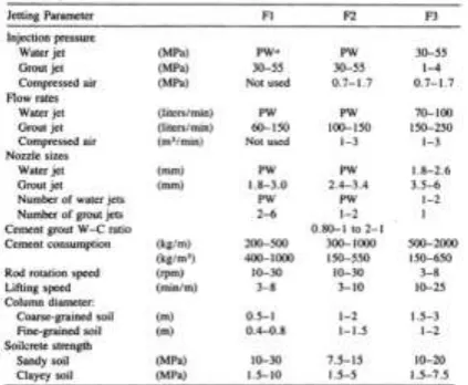
Z.-F. Wang (2012) Mentioned that Engineering experience in Seoul indicates that the unconfined compressive strength of the solidified columns can reach to 5.0–6.0 MPa after 28 days of curing to Grout W/C=1by weight. Table(2) provides a general summary of operational parameters and grouted soil strengths. Where F1, F2 and F3 are one fluid system, two fluid system and three fluid system respectively.(Xanthakos, et.al. (1994))
In the finite element model, Jet Grouting columns were represented by a wall with a thickness based on equivalent axial stiffness (Hamidi et al, 2009)
In this study the used jet grouting material was as which used by F. Tschuchnigg, H. F. Schweiger (2008). The diameter d has been taken as the true diameter and the stiffnesses of the piles are converted into equivalent stiffnesses according to their spacings (Table 3). The Mohr-Coulomb model is used to describe the behavior of the jet grouted columns. The interaction between jet grouted columns and the subsoil can be assumed as very rough hence no interface elements are defined between columns and soil.
Table (3). Properties of the jet grout piles for the 2D model Spacing
(m) type
γb
(kN/m3)
γsat
(kN/m3) υ Eref(kN/m
2) C
ref(kN/m2)
φ
(°)
2.00 drained 21.5 21.5 0.15 5000000 1350 32.5
3.3 Strip Footing
Strip footing can be simulated by beam element. This line element has bending stiffness, EI, and axial stiffness, EA. Where:
E: modulus of elasticity for concrete 4400 Fcu (N/mm2)
A: area of cross section I: moment of inertia
The footing is loaded with distributed load 100 kN/m2, which is transferred to soil. The properties of footing are given in Table (4).
Table (4) Material Properties For The Strip Footing
IV. FINITE ELEMENT MODEL
4.1 Finite Element Mesh
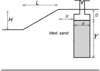
Fig. (1). presents the configuration of the problem under investigation and the corresponding variables that were assigned in the numerical model, H represents the vertical length of slope. L represents the horizontal length of slope.B represents the width of the footing and X represents the distance of the footing from the edge of slope. Y represents the depth of the depth of jet grouting underneath footing. Note that the distance X was measured, according to Meyerhof s theory, between slope crest and the footing edge which face to the side of slope. D represents the embedded depth of the footing. The tests were conducted with different value ofD and X in order to evaluate the variation of the settlement due to slope effect. The finite element mesh is generated automatically by the program as a very fine mesh to be more accurate in representation of slope behavior, as shown in Fig. (2)
Fig. (1) Model of slope, adjacent area and strip footing
Fig. (2) Finite Element Mesh For The Model Of Slope And Adjacent Area
Parameter Name Value Unit
Axial stiffness Flexural rigidity Equivalent thickness Weight
Poisson’s ratio
EA EI d w υ
3.811E+07 3.175E+06 1.00 25.00 0.2
4.2 Analysis Procedure
The elastic perfectly plastic finite element analysis involves a number of iterations. Four foundation depths models with Rd=D/H equal to be 0.0, 0.2, 0.4 and 0.6 were considered. For each foundation depth model, the
footing was placed in different location in horizontal direction. This location was based on the Rx=X/B ratio,
which was assigned to be equal to 0, 1, 2, 3, 4 and 5. The variation of the settlement with respect to the location of footing in horizontal direction can be observed with and without jet grouting underneath the footing. Table (5) presents the studied cases.
Table (5) Analysis Cases Used In The Numerical Study.
D/H X/B In case of
0 0.2 0.4 0.6
0 1 2 3 4 5
Before jet grouting With jet grouting Y/B =2 With jet grouting Y/B =3 With jet grouting Y/B =5 With jet grouting Y/B =10
V. ANALYSIS AND RESULTS
The effect of studied parameters on settlement values of strip footing may be presented as follows:
5.1. Deformation of Strip Footingbefore Jet
G
routin
g
Process
5.1.1 The Settlement of The Strip Footing
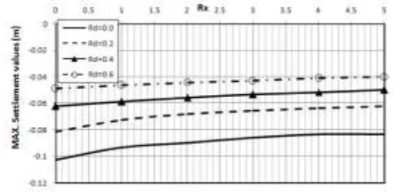
Figures (3) shows the relationship between settlement of strip foundation and (Rx) for Rd = 0.0, 0.2, 0.4, and 0.6.
The maximum settlement was found where the building is nearest to the slope crest. When the values of (Rx)
and (Rd) were increased, a corresponding decrease in the settlement of strip footing was recorded. At Rd = 0 the
maximum settlement at Rx = 0 has a value of 110 mm. Differential settlement can be observed which decrease at
Rx = 1. It can be observed that the settlement decrease by increasing the depth of foundation. At Rx ≥ 2no
considerable difference was noticed in the values of foundation settlement for all cases.
Fig. (3): Variation of The Maximum Foundation Settlement Values For Different Values
Of R
xand R
dBefore Jet Grouting.
5.1.2 The Horizontal Displacement of The Strip Foundation
Figure (4) shows the relationship between horizontal displacement of strip foundation and (Rx) for different
values of Rd. The maximum horizontal displacement was found where the building is nearest to the excavation.
When the values of (Rx) and (Rd) were increased, a corresponding decrease in the horizontal displacement of
strip footing was recorded. At Rd = 0 the maximum horizontal displacement at Rx = 0 has a value of 35 mm. At
Fig. (4): Variation of The Foundation Horizontal Displacement For Different Values Of R
xandRd before jet grouting.
5.2. Deformation of Strip Footingafter Jet
G
routin
g
Process
5.2.1 Influence of Jet Grouting Depth On Footing Settlement
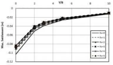
Figures (5, 6, 7, and 8) showInfluence of jet grouting depth on maximum values of footing settlementfor different values of Rx and Rd. Jet grouting provides an opportunity to significantly decrease footing settlement.
When the values of (Y/B) were increased, a corresponding decrease in the maximum settlement values of strip footing was recorded in the same case of Rx and Rd. The settlement values in all cases exhibited a decrease with
the increase in the Y/B values. As depicted in Figures (5, 6, 7, and 8), there is approximately 45%, 55%, 68% and 86% decrease in maximum footing settlement values due to the values of Y/B are 2, 3, 5 and 10, respectively for all cases.
Fig. (5): Influence of jet groutingdepth on max. Fig. (6): Influence of jet grouting depth on max.
Footing settlementfor different values of Rx footing settlementfor different values of Rx
and Rd=0m. and Rd= 0.2m.
Fig. (7): Influence of jet grouting depth on Fig. (8): Influence of jet grouting depth on
max. footing settlementfor different values of max. Footing settlementfor different values of
The reduction in maximum settlement values for strip footing adjacent to slope crest due to jet grouting process for medium sand may be expressed as follows:
Where:
Sf = settlement after jet grouting
Si = settlement befor jet grouting
5.2.2 Influence of Jet Grouting Depth OnFooting Horizontal Displacement
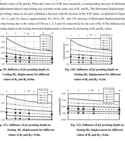
Figures (9, 10, 11, and 12) show Influence of jet grouting depth on footing Horizontal displacementvalues for different values of Rx and Rd. When the values of (Y/B) were increased, a corresponding decrease in Horizontal
displacementvaluesof strip footing was recorded in the same case of Rx and Rd. The Horizontal displacement of
strip footing values in all cases exhibited a decrease with the increase in the Y/B values. As depicted in Figures (9, 10, 11, and 12), there is approximately 4%, 6%%, 8% and 12% decrease in Horizontal displacementvalues of strip footing due to the values of Y/B are 2, 3, 5 and 10, respectively for the case of Rx=0.The Influenceof jet
grouting depth on the footing horizontal displacement is decrease by increasing of Rx and Rd values.
Fig. (9): Influence of jet grouting depth on Fig. (10): Influence of jet grouting depth on
f ooting Hz. displacement for different footing Hz. displacement for different
values of Rx and Rd=0.0m. values of Rx and Rd= 0.2m.
Fig. (11): Influence of jet grouting depth on Fig. (12): Influence of jet grouting depth on
footing Hz. displacement for different footing Hz. displacement for different
values of Rx and Rd= 0.4m. values of Rx and Rd= 0.6m.
VI. CONCLUSIONS
the relativedepth of foundation, Rd= D/H and the second is the relative distance,Rx Χ B, X is the building
distance. The reduction influence of jet groutingon footing displacement were studied and investigated. The jet grouting height,Y values are 2B, 3B, 5B and 10B.The following conclusions can be drawn from the obtained results:
The maximum settlement was found where the footing is nearest to the slope crest. When the values of (Rx)
and (Rd) were increased, a corresponding decrease in the settlement of strip footing was recorded.
The maximum horizontal displacement of footing was found where the footing is nearest to the slope crest.
When the values of (Rx) and (Rd) were increased, a corresponding decrease in the settlement of strip footing
was recorded.
Jet grouting provides an opportunity to significantly decrease footing settlement. When the values of (Y/B)
were increased, a corresponding decrease in the maximum settlement values of strip footing was recorded in the same case of Rx and Rd.
The settlement is approximately 45%, 55%, 68% and86%decrease in maximum footing settlement values
due to the values of Y/B equal to 2, 3, 5 and 10, respectively for all cases of Rx and Rd.
When the values of (Y/B) were increased, a corresponding decrease in Horizontal displacementvalues of
strip footing was recorded in the same case of Rx and Rd.
REFERENCES
1- Alp Gokalp and RasinDuzceer (2001). Ground improvement by jet grouting technique for foundations of a natural gascombined cycle power plant in turkey, Kasktas A.S., Istanbul, Turkey
2- Ayres, D. J.(1959). Grouting and the civil engineer, Transactionsof the Society of Engineers, 114–124. 3- Ayres, D. J.(1961). The treatment of unstable slopes andrailway track formations, Journal of the Society of
Engineers,52, 111–138.
4- Ayres, D. J.(1985). Stabilization of slips in cohesive soilsby grouting, in Failures in Earthworks, Thomas Telford,London.
5- BabakHamidi, Michal Krzeminski, Daniel Berthier, Philippe Vincent, Murray Yates and Menard Bachy,The application of jet grouting for the construction ofSydney International Airport Runway end safety area
6- F. Tschuchnigg, H. F. Schweiger (2008). Comparison of different models for analyzing foundations on jetgrout columns, Computational Geotechnics Group, Institute for Soil Mechanics and Foundation Engineering, Graz University of Technology, Graz, Austria.
7- HAMIDI, B., NIKRAZ, H. & VARAKSIN, S. (2009) Arching in Ground Improvement. Australian Geomechanics Journal, (December), 99-108.
8- Handy, R. L., and Williams, N. W. (1967). Chemical stabilizationof an active landslide, Civil Engineering, 37(8),62–65.
9- J. M. Duncan and S. G. Wright.(2005) Soil Strength andSlope Stability, Published by John Wiley & Sons, Inc., Hoboken, New Jersey
11-Rogers, C. D. F., and Glendinning, S. (1993). Stabilizationof embankment clay fills using lime piles, Proceedingsof the International Conference on Engineered Fills, Thomas Telford, London, pp. 226–238. 12-Rogers, C. D. F., and Glendinning, S.(1994). Deep SlopeStabilization Using Lime, Transportation
Research Record1440, Transportation Research Board, National ResearchCouncil, National Academy Press, Washington,DC, pp. 63–70.
13-Rogers, C. D. F., and Glendinning, S. (1997). Improvementof clay soils in situ using lime piles in the UK, EngineeringGeology, 47(3), 243–257.
14-SanazSayehvand and BehzadKalantari, (2012) Use of Grouting Method to Improve SoilStability Against Liquefaction—A Review Vol. 17 [2012], Bund. K EJGE.
15-Smith, R., and Peck, R. B. (1955). Stabilization by pressuregrouting on American railroads, Geotechnique, 5, 243–252.
16-S.V. Anil Kumarand K. Ilamparuthi(2009). Response of Footing on Sand Slopes, IGC, Guntur, INDIA. 17-W. R. Azzam and A. Farouk(2020). Experimental and Numerical Studies of Sand Slopes Loaded with
Skirted Strip Footing, EJGE, Vol. 15, Bund. H.