REVIEW OF METHODS TO INCREASE
PERFORMANCE OF SHELL AND TUBE HEAT
EXCHANGER
Amit
Department of Mechanical Engineering, National Institute of Technology Kurukshetra (India)
ABSTRACT
Increasing efficiency of the processes and devices is always desired from engineers. These requirement may
arise as a result of the need to increase process output, increase profitability, or accommodate capital
limitations. Processes which use heat transfer equipment must frequently be improved for these reasons. This
report provides some methods for increasing shell-and-tube exchanger performance. Themethods consider
whether the exchanger is performing correctly after their application and whether there is some increase in
efficiency or effectiveness of the heat exchanger.
I.INTRODUCTION
Increasing heat exchanger performance usually means transferring more duty or operating the exchanger at a closer temperature approach. This can be accomplished without a dramatic increase in surface area. Thisconstraint directly translates to increasing the overall heat transfer coefficient, U. The overall heat transfer coefficient is related to the surface area, A, duty, Q, and driving force, ΔT. This equation is found in nearly all
heat exchanger design references [1]:
Q=UA∆T
As stated in this form, U can be calculated from thermodynamic considerations alone. This calculation results inthe required U such that the heat is transferred at the stated driving force and area. Independent of this requiredU based on thermodynamics, an available U can be determined from transport considerations. For thiscalculation, U is a function of the heat transfer film coefficients, h, the metal thermal conductivity, k, and any fouling considerations, f. An exchanger usually operates correctly if the value of U available exceeds the Urequired.
The precise calculation of U from the transport relationships accounts for all of the resistances to heat transfer.These resistances include the film coefficients, the metal thermal conductivity, and fouling considerations. Thecalculation of U is based upon an area. For shell-and-tube exchangers, the area is usually the outside surface ofthe tubes [1].
U=f(h ,k ,f ,A)
Theoverall heat transfer coefficient can also be calculated by the equation given below, provided the inside and outside filmcoefficients, hi and ho, and the fouling resistance, f, are known [1].
153 | P a g e This discussion is limited to the shell-and-tube type exchangers. These exchangers are the most common in theprocess industry and can be easily modified in most cases. Furthermore, there are many sources available toestimate the shell-and-tube heat exchanger performance. Other types of exchangers such as air coolers mayalso be applicable with respect to cleaning and the use of tube inserts. Most of the more exotic heat exchangerssuch as plate-fin type exchangers, are not easily modified or enhanced to increase performance and are notconsidered here. However, during an investigation to increase performance, some of the exotic exchangers maybe a viable alternative if all of the other options have been exhausted.
A plan for increasing heat exchanger performance for shell and tube exchangers should consider the following steps:
1. Determine that the exchanger is operating correctly as designed.Correcting flaws in construction and pipingthat may have a detrimental effect on heat transfer and pressure drop may be the solution.
2. Estimate how much pressure drop is available. For single phase heat transfer coefficients, higher fluidvelocity increases heat transfer coefficients and pressure drop.
3. Estimate fouling factors that are not overstated. Excessive fouling factors at the design state result inoversized exchangers with low velocities. These low velocities may exacerbate the fouling problem. More liberalfouling factors and periodic cleaning may increase the heat exchanger’s performance.
4. Consider using a basic shell-and-tube exchanger with enhancement or intensification such as finning, tubeinserts, modified tubes, or modified baffles.
One simple and obvious solution for increasing shell-and-tube heat exchanger performance might be to switch theshell-and-tube fluids. The placement of the process fluids on the tube or shell side is usually not dependent onthe most efficient heat transfer area. A primary concern is pressure. High-pressure fluids tend to be placed in thetubes rather than the shell, resulting in less construction material and a less expensive exchanger [2]. Handlingphase changes may dictate where fluids are placed. Switching the tube-and-shell side process streams may onlybe valid if the process streams have no phase change and are approximately the same pressure.
II. ENHANCED SURFACES
Figure 1Examples of heat transfer enhancement surfaces of tubes.
II. FINNING
Tubes can be finned on both the interior and exterior. This is probably the oldest form of heat transferenhancement. Finning is usually desirable when the fluid has a relatively low heat transfer film coefficient as doesa gas. The fin not only increases the film coefficient with added turbulence but also increases the heat transfersurface area. This added performance results in higher pressure drop. However, as with any additional surfacearea, the fin area must be adjusted by an efficiency. This fin efficiency leads to anoptimum fin height with respectto heat transfer [4]. Most of the heat transfer and film coefficients for finned tubes are available in the open literatureand supported in most commercial heat exchanger rating packages.
155 | P a g e III.TUBE INSERTS
Inserts, turbulators, or static mixers are inserted into the tube to promote turbulence. These devices are mosteffective with high viscosity fluids in a laminar flow regime. Increase in the heat transfer film coefficientscan be as high as five times [5]. Inserts are used most often with liquid heat transfer and to promote boiling. Tube inserts are used to remove fouling from inside surface of tubes of heat exchanger [6].
Insertsare not usually effective for condensing in the tube and almost always increase pressure drop. Because of thecomplex relationships between the geometry of the insert and the resulting increase in heat transfer and pressuredrop, there are no general correlations to predict enhancements. However, through the modification of thenumber of passes, a resulting heat transfer coefficient gain can be achieved at lower pressure drop in somesituations
IV. TUBE DEFORMATION
Many vendors have developed proprietary surface configures by deforming the tubes. The resulting deformation appears corrugated, twisted, or spirally fluted. The surface condenses steam on the outside and heats water on the inside. The author reports a 400 % increase in the inside heat transfer film coefficient [7]; however, pressure drops were 20 times higher relative to the unaltered tube at the same maximum inside diameter.
Figure 3 Cleaning fouling using tube inserts.
V. BAFFLES
Deficiencies of thesegmented baffle include the potential for dead spots in the exchanger and excessive tube vibration.Baffle enhancements have attempted to alleviate the problems associated with leakage and dead areas in theconventional segmental baffles.
The most notable improvement has resulted in a helical baffle. Baffle is most effective for high viscosity fluids and provide several refinery applications. Baffles promote nearly plug flowacross the tube bundle. The baffles may result in shell reductions of approximately 10-20% [8].
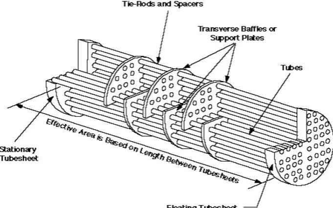
Figure 4 Transverse baffles used to redirect the flowing fluid.
VI.CONCLUSION
Engineers can evaluate increasing heat exchanger performance through a logical series of steps. The first stepconsiders if the exchanger is initially operating correctly. The second step considers increasing pressure drop ifavailable in exchangers with single-phase heat transfer. Increased velocity results in higher heat transfercoefficients, which may be sufficient to improve performance. Next, a critical evaluation of the estimated foulingfactors should be considered. Heat exchanger performance can be increased with periodic cleaning and lessconservative fouling factors. Finally, for certain conditions, it may be feasible to consider enhanced heat transferthrough the use of finned tubes, inserts, twisted tubes, or modified baffles.
REFERENCES
[1] Shah RK, Sekulic DP. Fundamentals of heat exchanger design. John Wiley & Sons; 2003 Aug 11.
[2] Sulzberger KJ, inventor; Tui Industries, assignee. Shell and tube heat exchanger. United States patent US
4,871,014. 1989 Oct 3.
157 | P a g e [4] GANAPATHY, V., “Design and Evaluate Finned Tube Bundles,” Hydrocarbon Processing, Vol 75, No 9,
pp. 103-111, Sep 1996.
[5] Eiamsa-Ard S, Promvonge P. Performance assessment in a heat exchanger tube with alternate clockwise and counter-clockwise twisted-tape inserts. International Journal of Heat and Mass Transfer. 2010 Mar 31;53(7):1364-72.
[6] MUKHERJEE, R., “Conquer Heat Exchanger Fouling,” Hydrocarbon Processing, Vol 75, No 1, pp.
121-127, Jan 1996.
[7] Lunsford KM. Increasing heat exchanger performance. Hydrocarbon engineering. 1998 Mar;77:786-93. [8] Lei YG, He YL, Li R, Gao YF. Effects of baffle inclination angle on flow and heat transfer of a heat