193 | P a g e
Comparison of regular buildings with
and without core wall
Prof. Mahadeva M
1, Prof. Manjunath S
2, Prof.Shirisha Y C
31,2
Department of Civil Engineering, Shri Pillappa College of Engineering, (India)
3
Department of CTM, Acharya Institute of Technology, (India)
ABSTRACT
A detail study of structural behaviour of the regular buildings with and without core wall Is done under
seismic load which is essential for appropriate design and their better performances. In the present study
4*3 bay, 5 storey medium rise structure with provision of lift core wall and each storey height 3m is
considered. analysis done by using e tab software. The analysis are carried out under different soil
condition i.e hard soil, medium and soft soil. Responses for storey drift and displacement is plotted for
different soil conditions.
Keywords : Base Shear, Core wall, E-Tabs, Infill loads, Joint displacement, Storey drift, Seismic
Behaviour
I. INTRODUCTION
The rapid development of urban population and the pressure on limited space significantly influence the
residential development of the city. The price of the land is increasing day by day, the desire to avoid uneven
and uncontrolled developing of urban area and bear the needs of land for important agricultural production
activity have all led to route residential building upwards. The local topographical restrictions in the urban area
are the only cause for the construction of multi-storey buildings to full fill the residential needs.
A core wall is nothing but a shear wall provided in the centre of the building to give more resistance to the
building. These are the reinforced concrete members provided to withstand lateral loads in the high rise
building. Core walls will be provided throughout the height of the building. These are provided around the stair
case or lift or around the both. Core wall will provide more strength and stiffness to the structure.
Core wall be designed according to the code provisions. Core wall in the building acts like cantilever beam
started from the base. Core wall has shear force and bending moment because of its height. Around the core wall
slabs are connected to it and on the other side connected to the columns and beams are connected in the same
way. It has high moment of inertia; hence it can withstand more loads. Core walls built with impervious
materials like steel, asphaltic concrete are provided as embankment of dam which prevents water leakage.
Increase in population particularly in metro cities, has resulted in demand for multi-storeyed buildings. As land
available for construction is limited, this has forced the planners to resort to vertical growth of the buildings in
form of multi-storeyed buildings. A building frame is subjected to both vertical as well as horizontal loads. The
vertical load consists of the dead weight of the structural components such as beams, slabs, columns etc. and
194 | P a g e
building to resist wind and other lateral forces depends on the rigidity of connections between the beams andcolumns.
The main objective of this project is to compare the regular building with & without core wall under earth quake
forces. Reinforced 5 storey’s framed structure is considered in the study and these types of buildings are mostly
observed in earth quake zone. Comparison to be done between regular buildings on the basis of joint
displacement, storey drift, base shear. Mainly we consider hard, medium and soft soil condition and how the
result of the structure varies.
II. MODELLING AND ANALYSIS
2.1. Introduction
ETABS- Extended Three Dimensional Analysis of Building Structures is developed specially as a computer
program for building systems. ETABS is now being used as an integral part of structural engineers, as to create
larger, more complex analytical models and to analyse using static and dynamic properties. This creating,
modelling and analysing, designing is possible as the interface is integrated with Microsoft windows. The results
are displayed graphically; also real time output of time-history displacements can be produced. ETABS provides
the user to construct a model as that of a real building like the terms used in here are column, beam, brace, and
wall, unlike that like nodes and finite elements. ETABS provides easy interface for using beams, columns, walls
in steel or concrete. Seismic and wind loads are generated accordingly to the needs of code requirements which
are made inbuilt in this computer program. The results can be got in ready format to make a document, making
the work a time saving one.
The working in the software is very easy. Firstly establish grid lines, define material property, structural
property, define loads and types of load combinations and assign the restraints and loads accordingly. Define the
seismic and wind loads according to the code requirements and then analyse it for any errors and then run the
model. The results will be got in the form of a tabular forms and also graphically which can be directly taken the
printout of these results and filed in a document. Different building models are analysed in ETABS. The
properties of building configurations are considered In present work are summarised below.
2.2. Models
Following are the different models which are consider in the analysis with plan irregularity under different soil
condition.
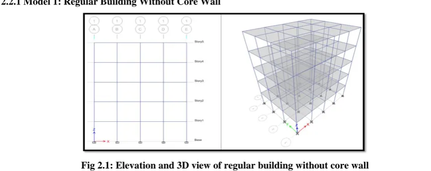
2.2.1 Model 1: Regular Building Without Core Wall
195 | P a g e
2.2.1 Model 2: Regular Building With Core WallFig 2.2: Elevation and 3D view of regular building with core wall
III. RESULTS AND DISCUSSION
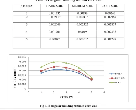
3.1 Storey Drifts
Lateral deflections are caused when buildings are subjected to seismic loads. The storey drift in any storey due
to least specified design lateral load, with partial load factor of 1.0 shall not exceed 0.004 times the storey
height, as per clause 7.11.1 IS1893:2000
Table 3.1 Regular building without core wall
STOREY HARD SOIL MEDIUM SOIL SOFT SOIL
1 0.001735 0.00198 0.00243
2 0.002119 0.002416 0.002967
3 0.002049 0.002327 0.002857
4 0.001701 0.0019 0.002333
5 0.00097 0.001016 0.001247
196 | P a g e
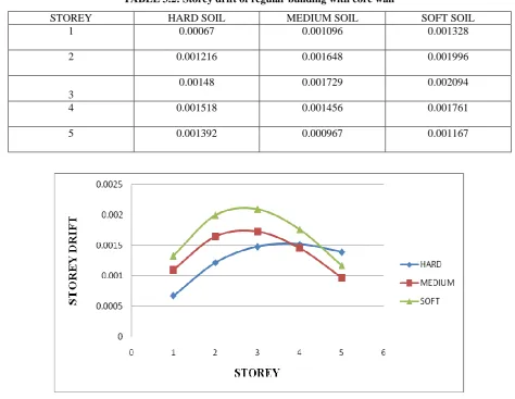
3.1.1. Regular building with core wallTABLE 3.2: Storey drift of regular building with core wall
STOREY HARD SOIL MEDIUM SOIL SOFT SOIL
1 0.00067 0.001096 0.001328
2 0.001216 0.001648 0.001996
3
0.00148 0.001729 0.002094
4 0.001518 0.001456 0.001761
5 0.001392 0.000967 0.001167
Fig 3.2: Storey drift of regular building with core wall
3.2.Displacement
The maximum displacement is consider along ‘x’ axis and ‘y’ axis.
3.2.1. Displacement of regular building without core wall
TABLE 3.3: Displacement of regular building without core wall
SOIL TYPE HARD MEDIUM SOFT
STOREY H Ux H Uy M Ux M Uy S Ux S Uy
1 3.2 5.2 3.7 5.9 4.5 7.3
2 7.8 11.6 8.9 13.2 10.9 16.2
3 12.3 17.7 14 20.2 17.2 24.8
4 16.1 22.8 18.2 25.9 22.4 31.8
197 | P a g e
Fig 3.3: Displacement of regular building without core wall3.2.2. Displacement of regular building with core wall
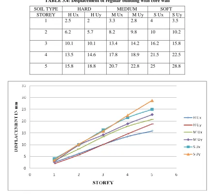
TABLE 3.4: Displacement of regular building with core wall
SOIL TYPE HARD MEDIUM SOFT
STOREY H Ux H Uy M Ux M Uy S Ux S Uy
1 2.5 2 3.3 2.8 4 3.5
2 6.2 5.7 8.2 9.8 10 10.2
3 10.1 10.1 13.4 14.2 16.2 15.8
4 13.5 14.6 17.8 18.9 21.5 22.5
5 15.8 18.8 20.7 22.8 25 28.8
198 | P a g e
IV. CONCLUSION
Maximum story drift found at middle stories of the structure for all the models.
Drift value of the building on soft soil building increased by 20% than medium soil building and medium
soil buildings increased by 10% than hard soil buildings.
Story drift of the building located on hard soil is less compared to the building located on medium and soft
soil.
As the drift value is less on hard soil, it is more suitable for the construction of buildings.
Displacement of the structure decreases if the core wall is added to the structure and it will decrease more
if the infill loads are added along with the core wall.
Story displacement increased as the soil condition varies from hard to medium to soft soil. Maximum value of displacement is found in soft soil.
REFERENCES
[1] Akil Ahmed, Seismic analysis of irregular buildings, International conference on interdisciplinary
research in engineering and technology(ICIDRET 2016), 18(2), 1998, 112-116.
[2] M Gowsalya, D Mahalakshmi, M Rajeshwari, S Sribha, Influence of soil conditions on the seismic
forces in the RC building by using ETabs, International journal of advanced research trends in
engineering and technology, ISSN-2394-3785, VOLUME 3, SPECIAL ISSUE 2, MARCH 2016
[3] A study on earthquake resistant construction techniques, American journal of engineering
research(AJER) volume 2 Issue 12, 258-264
BIOGRAPHAICAL DATA
Prof. Mahadeva M is working as assistant professor in civil engineering department form last 2 years and he also worked as assistant professor in k s institute of technology. He is national advisory board member for international conference and he secured a “Active Young
Researcher Award” from AR Research Publication and Conference World for continuous
contribution in the research field for shaping up the new era and He received is B E in civil
engineering and M.Tech with specialization in CAD structures from visvesvaraya
technological university. His research interest is in the field of soil structure interaction, structural engineering, earth quake engineering.
Prof. Manjunath S, working as an Assistant Professor in the Department of Civil Engineering
in SPCE from past two years. I have a total of 9 years of teaching experience. I have done my
B.E in Civil Engineering and M.Tech in Structural Engineering from VTU. I am a research
scholar, pursuing my P.hd in VTU and my area of research is water Resources, GIS and its applications.