209 |
P a g e
RESONANCE CHARACTERISTICS OF MICROSTRIP
ANTENNA AS A FUNCTION OF SUBSTRATE
THICKNESS
RitikaTandon
1, Alpana Singh
2, Saurabh Khanna
31,2
M.Tech Scholar, Subharti University Meerut, U.P. (India)
3
Assistant Professor, EN Department NIT, Meerut, U.P. (India)
ABSTRACT
A set of measurements of annular ring slot antennas on substrates of varying thickness is presented. The most
important factors in design of microstrip circuit and antenna are choice of the best substrate thickness and the
dielectric constant to have low losses. In this case an attempt has been made by selecting various dielectric
thicknesses to study return loss. For this, an annular ring slot microstrip antenna (ARSMSA) is designed at 3.0
GHz and simulated on different substrate thicknesses ranging from 0.5mm to 3.0 mm using Zeland IE3D
software. The variation in return loss is found from -5.869dB to -42.16.
Keywords: Microstrip Annular Ring Slot Antenna (ARSMSA), Return Loss, VSWR, Dielectric
Thickness
I. INTRODUCTION
Recent interest has developed in radiator etched on electrically thick substrates as these antennas are used for high frequency applications. However, microstrip antennas inherently have narrow bandwidth. In many cases, their increased impedance bandwidth is also paid for poorer radiation characteristics. Recent interest in millimeter wave systems and monolithic fabrication, however, has created a need for substrates that are electrically thicker, and/or have high permittivity. Increased bandwidth is another reason for interest in electrically thicker substrates. Anomalous results have been previously observed for printed antennas on such substrates. Many of the theoretical models, which worked well for thin, low dielectric constant substrates, fail to give good results for thicker or higher permittivity substrates.
210 |
P a g e
II. ANTENNA GEOMETRY AND DESIGN
The geometry of the proposed antenna is shown in Fig.1.The ground plane lies at the bottom side of the antenna with a very compact size of 21.75mm × 31mm × (0.5 to 3.0) mm. The radiation elements of the proposed antenna consist of an annular ring slot, operating approximately at 2.9 GHz (however a slight variation is also noticed in table 1 which is negligible for wideband operations ).m. The operating frequency is taken as 3 GHz. The other parameters are calculated using [7] and found as: W=31mm, h= (0.5 to 3.0) mm (assumed), εeff=4.63,
Leff=23.2mm, ∆L=0.72mm and L=21.75mm at εr=4.2. For a rectangular microstrip antenna the resonant
frequency is given as:
r r L L c f ) ( 2
Where length extension ( ΔL):
8 . 0 ) 258 . 0 ( 264 . 0 ) 3 . 0 ( 412 . 0 h W h W h L e ff e ff
Optimum value of W:
W= 2 / 1 2 ) 1 ( 2 r o and o e r r r f f 0
; also
e eo
e
Fig.1: annular ring slot antenna with W=31mm, h= (0.5 to 3.0)mm (assumed), εeff=4.63, Leff=23.2mm,
∆L=0.72mm and L=21.75mm at εr=4.2. fed by coaxial probe at (15.15mm, 2.975mm)
III. MEASUREMENTS AND RESULTS
211 |
P a g e
The results obtained are given in table 2. It can be observed that, variation in return loss is found from -5.869dB to -42.16 dB obtained for various substrates thickness.
Table I
Return Loss for Different Dielectric Thickness and Resonance Frequency
Return Loss(dB)→
Frequency
(MHz)↓
Thickness of Dielectric Substrate (mm)
0.2 0.5 0.75 1 1.25 1.75 2 2.5 2.75 3
2.874 -1.331 -4.535 -2.263 -2.287 -2.697 -4.578 -6.12 -11.48 -17.1 -27.63
2.879 -1.686 -6.325 -2.728 -2.652 -3.072 -5.149 -6.878 -13.09 -20.33 -30.49
2.889 -2.995 -16.05 -4.283 -3.757 -4.156 -6.748 -9.012 -18.31 -42.16 -20.31
2.896 -4.432 -19.8 -5.964 -4.817 -5.141 -8.151 -10.91 -25.01 -25.02 -16.72
2.897 -4.697 -17.19 -6.301 -5.016 -5.322 -8.404 -11.26 -26.72 -23.74 -16.28
2.905 -6.446 -8.187 -9.83 -6.917 -6.981 -10.7 -14.52 -29.89 -17.68 -13.61
2.912 -5.869 -4.776 -16.16 -9.894 -9.413 -14.03 -19.62 -19.53 -14.27 -11.67
2.913 -5.701 -4.57 -16.8 -10.24 -9.689 -14.41 -20.22 -19 -14.02 -11.52
2.92 -3.933 -3.069 -15.19 -14.52 -13.07 -18.86 -24.26 -15.05 -11.95 -10.18
2.927 -2.515 -2.115 -9.302 -16.68 -17.46 -20.66 -18.49 -12.24 -10.23 -8.999
2.93 -2.198 -1.901 -8.068 -15.32 -17.87 -19.24 -16.8 -11.54 -9.775 -8.672
Table II
Return Loss (Maximum Value) for Different Dielectric
Dielectric
thickness
Maximum dB
value
0.2 -5.869
0.5 -19.8
0.75 -16.8
1 -16.68
1.25 -17.87
1.75 -20.66
2 -24.26
2.5 -29.89
2.75 -42.16
3 -30.49
212 |
P a g e
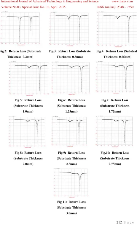
Fig.2: Return Loss (Substrate
Thickness 0.2mm)
Fig.3: Return Loss (Substrate
Thickness 0.5mm)
Fig.4: Return Loss (Substrate
Thickness 0.75mm)
Fig 5: Return Loss
(Substrate Thickness
1.0mm)
Fig.6: Return Loss
(Substrate Thickness
1.25mm)
Fig.7: Return Loss
(Substrate Thickness
1.75mm)
Fig 8: Return Loss
(Substrate Thickness
2.0mm)
Fig.9: Return Loss
(Substrate Thickness
2.5mm)
Fig.10: Return Loss
(Substrate Thickness
2.75mm)
Fig 11: Return Loss
(Substrate Thickness
213 |
P a g e
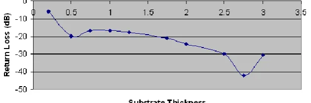
IV. CONCLUSION
This paper has presented a set of measurements of annular ring slot antennas on substrates of different thickness and fixed permittivity equal to 4.2.Therefore for the design of a radiator se1ection of suitable substrate thickness is very essential. The results shown in figure 12 are very useful f o r selection of suitable substrates for specific annular ring slot antenna applications. For the annular ring slot microstrip antenna (ARSMSA) designed at 3.0 GHz and simulated on different substrate thicknesses ranging from 0.5mm to 3.0 mm using Zeland IE3D software, the variation in return loss is found from -5.869dB to -42.16. A slight variation in resonance frequency is also noticed which can be neglected for wideband application.
Fig 12. Return Loss vs Substrate Thickness Curve
REFERENCES
[1].
Bahl I J & B Bhartia,"Microstrip Antennas", Arctech House. pp. 1-65.[2].
D M Pozar & S M Voda, " A Rigorous Analysis of Microstripline fed patch antenna" IEEE Trans. on A& P, Vol. No.6, 1982.
[3].
M Kara, "Effective p e r m i t t i - v i t y of rectangular microstri p antenna elements w i t h variousthickness of substrates", Microwave 8 Optical Technology, Vol. 10, Issue 4, Nov. 1995.
[4].
Daniel H. Schaubert,David M. PozarAndrew Adrian‖ 1989Effect of Microstrip Antenna SubstrateThickness and Permittivity: Comparison of Theories with experiment‖ IEEE transactions on antennas and propagation, vol. 31, No. 6.
[5].
J. Bahl and P. Bhartia, ―Design of microstrip antennas covered with a dielectric layer,‖ IEEE Trans.Antennas Propagat., vol. AP-30, pp. 314-318, Mar.1982.
[6].
C. A. Balanis, Antenna Theory Analysis and Design. 3rd ed., Hoboken, New Jersey: Wiley, 2005.chapter14.