SELECTION OF EFFECTIVE MITIGATION METHOD
FOR INRUSH CURRENT IN POWER TRANSFORMER
Ruchi Harchandani
1, Rashmi Kale
21,2
Asstt. Prof., Department of Electrical Engineering, F.C.R.I.T., Maharashtra,( India)
ABSTRACT
Power Transformers are energized depending on load requirement by closing of circuit breakers which generate asymmetrical flux and result into saturation of transformer core. Due to which huge transient magnetizing inrush current is generated. Inrush current can be as high as ten to fifteen times its rated current. The magnitude of inrush current depends upon residual flux, angle of voltage during energization of transformer, source strength, and leakage impedance. This inrush current will further increase if a feeder containing multiple transformers is energized. DC-component of inrush transient currents of the incoming transformer generates additional saturation in the already connected transformers.
The inrush current in transformer could cause many problems from mechanical stress on transformer windings to harmonics injection, and system protection malfunction. Tripping of electrical protective devices may be caused by the asymmetrical voltages and prolonged transient harmonic overvoltage, affecting the stability and reliability of the whole electrical systems. Different methods to reduce this inrush current have been discussed and implementation of Dynamic Voltage Restorer (DVR) to control inrush current is highlighted in this paper.
Keywords:
Dynamic voltage restorer, Inrush current, Mitigation, Saturation, TransformerI.
I
NTRODUCTIONThe excitation characteristic of the transformer core is a nonlinear relationship between the flux and
magnetizing current. The operating range of magnetic field for transformers is in linear region. In the steady
state, transformers are designed to operate below the knee point of their saturation curve. However, when
transformers are energized, flux can rise to a high value in the saturation region and magnetizing current
increases drastically. When a transformer is first energized, a transient current up to 10 to 15 times larger than
the rated transformer current can flow for several cycles. Worst case inrush happens when the primary winding
is connected at an instant around the zero-crossing of the primary voltage, (for a pure inductance would be the
current maximum in the AC cycle). This inrush current will further increase if a feeder containing multiple
transformers is energized.
Load
Heavy Load 1
Heavy Load 2
Parallel Transformers
Source T1
T2
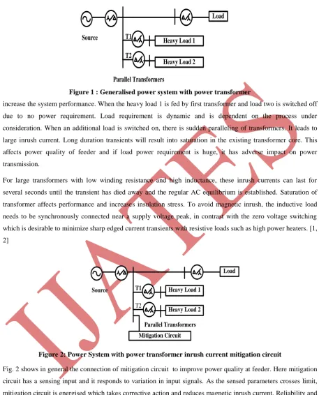
Figure 1 : Generalised power system with power transformer
increase the system performance. When the heavy load 1 is fed by first transformer and load two is switched off
due to no power requirement. Load requirement is dynamic and is dependent on the process under
consideration. When an additional load is switched on, there is sudden paralleling of transformers. It leads to
large inrush current. Long duration transients will result into saturation in the existing transformer core. This
affects power quality of feeder and if load power requirement is huge, it has adverse impact on power
transmission.
For large transformers with low winding resistance and high inductance, these inrush currents can last for
several seconds until the transient has died away and the regular AC equilibrium is established. Saturation of
transformer affects performance and increases insulation stress. To avoid magnetic inrush, the inductive load
needs to be synchronously connected near a supply voltage peak, in contrast with the zero voltage switching
which is desirable to minimize sharp edged current transients with resistive loads such as high power heaters. [1,
2]
Load
Heavy Load 1
Heavy Load 2
Parallel Transformers
Mitigation Circuit
Source T1
T2
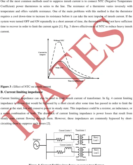
Figure 2: Power System with power transformer inrush current mitigation circuit
Fig. 2 shows in general the connection of mitigation circuit to improve power quality at feeder. Here mitigation
circuit has a sensing input and it responds to variation in input signals. As the sensed parameters crosses limit,
mitigation circuit is energised which takes corrective action and reduces magnetic inrush current. Reliability and
fast response are desired features of mitigation. Inrush current recurrence depends on its own swiching and
adjcent transformer switching. If number of transient switching are more, then to maintain consistent
II.
D
IFFERENTM
ETHODSThere are many possible mitigation methods which are discussed below are different circuits which are effective
in certain operating conditions.
A.
NTC Power Thermistor
One of the most common methods used to suppress inrush current is to connect NTC (Negative Temperature
Coefficient) power thermistors in series to the line. The resistance of a thermistor varies inversely with
temperature and offers variable resistance. One of the main problems with this method is that the thermistor
requires a cool down-time to increase its resistance before it can take the next impulse of inrush current. If the
system were turned OFF and ON repeatedly in a short amount of time, the thermistors would not have sufficient
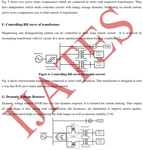
time to recover in order to limit the current again [1]. Fig. 3 shows effectiveness of NTC to reduce heavy inrush
current.
Time in millisecond Current in
Ampere
Without NTC
With NTC
Figure 3 : Effect of NTC on inrush current
B. Current limiting impedance
Current limiting impedance can also be used to limit inrush current of transformer. In fig. 4 current limiting
impedance is shown that would be bypassed by a short circuit after some time has passed in order to limit the
current at the start, but still conserve power in steady state. This impedance could be a resistor, an inductance, or
a series combination of both. The drawback of current limiting impedance is power losses that result from
steady state current flowing through them. However, these impedances are commonly bypassed by
short-circuiting them to suppress such losses [2].
Heavy Load 2 Heavy Load 1 Substation
Current Limiter 1
Current Limiter 2
Transformer 1
Transformer 2
The response time of current limiter is decided by its time constant. There has to be optimied value for such
circuits which cannot be generalised. When heavy inrush current start flowing through operating transformer,
limiter damps its magnitude. It has coulped in such a way which demagnetises to avoid saturation current.
C. Synchronous Closing
Each winding of the transformer should be switched at the maximum of the voltage so that inrush current can be
reduced to avoid saturation. Also by triggering the system at a phase angle that is different from the supply
voltage source inrush current can be minimized. The concept behind this technique is to trigger the circuit at the
specific phase at which the transient response of the circuit would be minimized. In order to trigger the system
at a specific phase-angle compared to the voltage source, a delay can be implemented in the switching
mechanism that depends on the phase-angle which depends upon the impedance of the system. Such delays are
usually achieved by a separate clock, synchronized with the voltage source [3].
If we choose to switch transformers at voltage zero-crossing instant, the calculated inrush currents will be
approximately 10% higher. It is observed that the total inrush currents for four, eight, and sixteen transformers
are 23%, 26%, and 27% larger than for a single transformer, respectively.
D. Tap changer utilization
To reduce the inrush current, a higher impedance of the winding is required so, connecting the transformer using
the maximum number of turns (lowest tap) in the windings to increase the impedance and reducing the inrush
current and their effects. This possibility was accepted due to their reduced cost and easy application. Thyristor
tap changers may be configured to provide continuous or discrete level control. Continuous control is based on
delay angle control, Delay angle control generates harmonics. To achieve little or no harmonic generation, tap
changer must provide discrete level control [4].
E. Active Series Compensators
An active inrush current compensator is capable of reducing the inrush current effectively during startup. The
proposed compensator is based on an inverter-based series compensator which is comprised of a single-phase
inverter and series transformer. Voltage sags are very frequent events with energization of transformer or
starting of large motors although their duration is very short. Hence, during voltage stabilizer mode, the existing
series compensator is controlled by a voltage stabilizer controller and superimposes a compensating voltage on
the inverter output whenever the load voltage deviate from the nominal value. This strategy is easier to
implement because it requires no information of the transformer parameters [6]. Each power transformer should
have dedicated series compensator. Active series compensator has to be critically designed to avoid losses in the
form of heat. The magnetic coupling is again in anti-phase if the amount of current passing through compensator
is exceeding set value. Switching in the compensator is fast to have proper demagnetizing effect during
Active Series Compensator 2 Active Series Compensator 1 Heavy Load 2 Heavy Load 1 Substation Transformer 1 Transformer 2
Figure 5: Mitigation by active series compensator
Fig. 5 shows two active series conpensators which are connected in series with respective transformers. They
have independent switch mode controller circuits with energy storage elements. Depending on inrush current,
active series compensator acts to limit current of transformer.
F. Controlling BH curve of transformer
Magnetising and demagnetizing pattern can be controlled to limit large inrush current . It is achieved by
resonanting transformer with LC circuit. It is more optimized for medium loading condition [7].
B H Heavy Load 2 Heavy Load 1 Substation Transformer 1 Transformer 2 Ferroresonant Transformer Load Figure 6: Controlling BH curve for inrush current
Fig. 6 shows ferroresonant transformer connected in series with substation. This transformer is designed in such
a way that B-H curve limits individual inrush current.
G. Dynamic Voltage Restorer
Dynamic voltage restorer (DVR) has very fast dynamic response. It is featured for current limiting. Thus impact
of overvoltage is less. Along with compensation, the harmonics are minimized to improve power quality.
Voltage restoration helps in minimizing the fault impact as well as increase stability [7-8].
Heavy Load 2 Heavy Load 1 Substation DVR 1 DVR 2 Transformer 1 Transformer 2 Load
Figure 7: Dynamic voltage restorer as mitigation circuit
H. Ultra fast capacitor
An ultra-fast capacitor (UF capacitor) charging and discharging reduces transients. Ultra capacitor is source of
energy. It acts as a dynamic voltage source. Two control switches are connected in parallel and this combination
is connected in series. One switch controls charging while another is present in discharging. Controller signals
are controlling switches. The closed loop operation can be achieved based in the value of overvoltage [9].
I. Inrush current limiting reactors
This method employs reactors in series with the capacitor bank. The reactor increases the magnitude of the
surge impedance, effectively reducing the peak value of the inrush current. Also, since the current through the
reactor cannot change instantly, the higher frequency components of the transient are limited and the severity of
the current inrush transient is reduced. Sometimes reactors are built intentionally with higher resistances to
increase damping of the transient [10].
J. Energized by a less capable source
If energized by a less capable source, such as a generator set, the current inrush would be somewhat less than
when energized by a utility line, but still very large because of the large short circuit current capability of a
synchronous generator. In either case, the severe power transient induced by switching on transformers can be
very disruptive to the electrical system, particularly when it is being powered up.
If the utility line is live, switching on transformers would not induce a significant inrush current if the
transformers were to be energized in a stagger mode allowing sufficient time for the inrush current on each
transfer to decay sufficiently (typically 2 to 3 seconds) before switching on the next transformer [11].
However, typically due to cost constraints, in most cases the connection between the transformer and the utility
line would be made using a fuse protected switch which would not allow for staggering transformer switch-on,
and therefore, all transformers would be energized simultaneously. Energizing multiple transformers at once
would then induce a much stronger inrush current onto the utility line, but with a reasonable stiff power source it
would be well within the utility source capabilities.
III.
SIMULATION
RESULTS
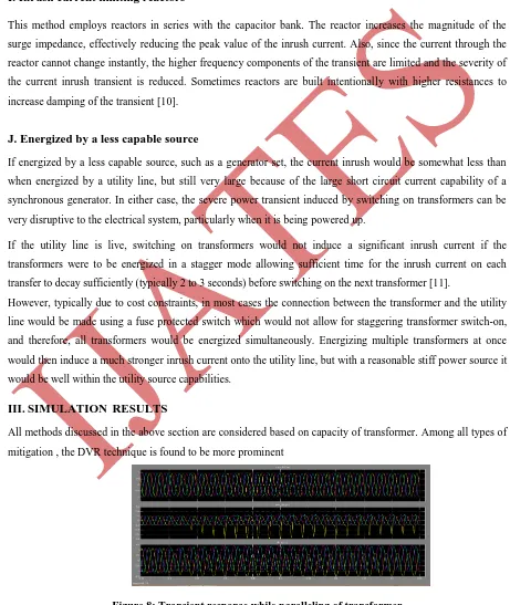
All methods discussed in the above section are considered based on capacity of transformer. Among all types of
mitigation , the DVR technique is found to be more prominent
Figure 9: Transient response while paralleling of transformer without Dynamic voltage Restorer
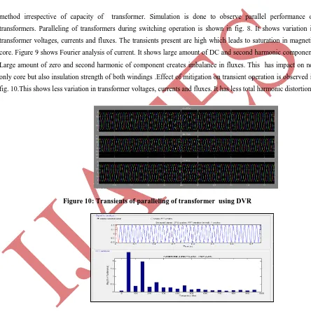
method irrespective of capacity of transformer. Simulation is done to observe parallel performance of
transformers. Paralleling of transformers during switching operation is shown in fig. 8. It shows variation in
transformer voltages, currents and fluxes. The transients present are high which leads to saturation in magnetic
core. Figure 9 shows Fourier analysis of current. It shows large amount of DC and second harmonic component.
Large amount of zero and second harmonic of component creates imbalance in fluxes. This has impact on not
only core but also insulation strength of both windings .Effect of mitigation on transient operation is observed in
fig. 10.This shows less variation in transformer voltages, currents and fluxes. It has less total harmonic distortion
Figure 10: Transients of paralleling of transformer using DVR
Figure 11: Harmonic analysis transient response while parellilng of transformer using Dynamic voltage
Restorer
IV.
CONCLUSIONIn the paper the effects of transformer inrush current on power system and several techniques have been
mentioned which can mitigate inrush current due to energization of transformer. Depending upon the system
requirement and costing, method can be chosen. NTC is most common and widely used device for inrush
current mitigation where the frequency of operation is limited. DVR systems have the advantage that they are
highly efficient and have very fast response. Tap changer method is one of the cheapest techniques. This method
has variable and accurate control. Synchronous closing is the most efficient and can reduce the inrush current to
great extent. Ultra-capacitor is more attractive futuristic mitigation method. This paper highlights on DVR
mitigation technique by using proper simulation and analysis of with and without mitigation. Simulation results
shows large reduction in harmonics and thus in total harmonic distortion of power transformers.
References
[1] Lisbôa, C. A., Erigson, M. I., and Carro, L., “ System level approaches for mitigation of long duration transient faults in future technologies,” 12th IEEE European Test Symposium (ETS'07),2007.
[2] J. Pontt, J. Rodriguez, J. San Martin,,R. Aguilera., “ Mitigation of sympathetic interaction between powertransformers fed by long
Over Head Lines caused by inrush transient currents,”
[3] Salman Kahrobaee, Marcelo C. Algrain, Sohrab Asgarpoor, “Investigation and Mitigation of Transformer Inrush Current during Black
Start of an Independent Power Producer Plant, Energy and Power Engineering, 2013, 5, 1-7.
[4] R.Elliott. (2011, November 11) Inrush Current Mitigation [Online]. Available:http://www.sound.westhost.com
[5] Ametherm, Inc. "How To Stop Inrush Current". Internet: www.ametherm.com/inrush-current/how-to-stop-inrush-current.html, 2010
[Dec. 15, 2011].
[6] A. C. Lippincott and R. M. Nelms. A capacitor-charging power supply using a series-resonant topology, constant on-time/variable
frequency control, and zero-current switching. Industrial Electronics, IEEE Transactions on 38(6), pp. 438-447. 1991.
[7] Cokkinides, G.J., Stefopoulos, G, “ Voltage Stability and Voltage Recovery: Load Dynamics and Dynamic VAR Sources Power
Systems Conference and Exposition, 2006. PSCE '06. 2006 IEEE PES, Oct. 29 2006-Nov. 1 2006 ,page(s):124 - 131 E-ISBN
:1-4244-0178-X Print ISBN:1-4244-0177-1
[8] Chris Fitzer, Atputharajah Arulampalam, Mike Barnes, and Rainer Zurowski , “ Mitigation of Saturation in Dynamic Voltage
Restorer
[9] Connection Transformers”IEEE Transactions on Power Electronics, Vol. 17, No. 6, November 2002,pp.1058-1066.
[10] “ Voltage Sag , Mitigation Endeavour Energy Power Quality & Reliability Centre,University of Wollongong
[11] Alexander E. Emanuel, “ Inrush Transient Current Mitigation,” 2012
[12] Seyed mohammad hassan hosseini, hadi samadzadeh,javad olamaei,murtaza farsadi, “ SSR mitigation with SSSC thanks to fuzzy control” Turkish Journal of Electrical Engineering & Computer Sciences,2013.
[13] Baris Kovan, Francisco de León, Dariusz Czarkowski, M,Zivan Zabar, and Leo Birenbaum,“Mitigation of Inrush Currents in Network
Transformers by Reducing the Residual Flux with an Ultra-Low-Frequency Power Source”
[14] Sag Proofing Technologies Inc, Installation and Service Manual - Voltage-Sag Compensators, 2005.
[15] J. J. Grainger and W. D. Stevenson, Jr., Power System Analysis. Singapore , McGraw-Hill Inc., 1994, pp. 76–80.
[16] G. Benmouyal, E. O. Schweitzer, III, and A. Guzmán, “Synchronized Phasor Measurement in Protective Relays for Protection,
Control, and
Analysis of Electric Power Systems,” proceedings of the 29th Annual Western Protective Relay Conference, Spokane, WA, October