a
Corresponding author: [email protected]
LHC MACHINE: STATUS AND PLAN
Mirko Pojer1a
1
CERN, CH-1211 Geneva 23, Switzerland
Abstract. The LHC Run I was successfully concluded in March 2012. An incredible amount of data has been collected and the performance continuously improved during these three years. Important information on the limitations of the machine also emerged, which will be used to further increase the potential of the machine in the coming years.
1 Setting the scene
The operation of the LHC in its first run was accompanied by an amazing escalade in the performance which lead to a peak luminosity close to the nominal design value [1]: 7.7 1033 cm-2s-1 to be compared with the nominal 1034 cm-2s-1. These luminosities imply a number of collisions per crossing between 30 and 50, resulting in 109 collisions per second: a big challenge not only for the experiments (which have to deal with very complicate collision pattern to distinguish and analyse) but also for the data mining and storage, with 15 million gigabytes of data produced per year and an incredible computational power required.
In terms of challenges for the LHC, the machine is working at a factor 200 in stored beam energy (360 MJ) with respect to any other machine ever built, with a factor 2 in magnetic field and a factor 7 in beam energy.
1.1 The collimation system
To operate at nominal performance the LHC requires a large and complex (multi-stage) collimation system. Differently from previous colliders (which used collimators mostly for experimental background conditions) the LHC can, in fact, only run with collimators, due to the very small quench limit (few mJ/cm3) of its magnets. And the collimation hierarchy has to be respected at any stage of operation in order to achieve satisfactory protection and cleaning.
As explained in §2.1, lower * implies tighter collimator settings as well as a careful alignment, together with beam sizes and orbit well within tolerance.
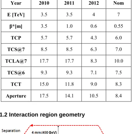
In Table 1, the settings for all collimators are listed, as they were used during the three years of operation. The aperture values are listed too, together with the energy and * attained.
Table 1. Summary of collimator settings (in normalized sigmas) used during the three years of operation.
Year 2010 2011 2012 Nom
E [TeV] 3.5 3.5 4 7
β*[m] 3.5 1.0 0.6 0.55
TCP 5.7 5.7 4.3 6.0
TCS@7 8.5 8.5 6.3 7.0
TCLA@7 17.7 17.7 8.3 10.0
TCS@6 9.3 9.3 7.1 7.5
TCT 15.0 11.8 9.0 8.3
Aperture 17.5 14.1 10.5 8.4
1.2 Interaction region geometry
Figure 1. Separation and crossing angles.
In the IRs, the beams are first combined into a single common vacuum chamber and then re-separated in the horizontal plane. Because of the tight bunch spacing and to prevent undesired parasitic collisions, in the region
EPJ Web of Conferences 60, 01002 (2013) DOI: 10.1051/epjconf/20136001002
© Owned by the authors, published by EDP Sciences, 2013
where the beams circulate in the common vacuum chamber, a parallel separation is applied in one plane (mostly effective at the IP), which is collapsed to 0 when the beams are colliding; a crossing angle is also used in the other plane.
2
What limits machine performance?
Two are the main drivers for the improvement of the performance of a machine: more energy and more luminosity. For the first case, it means increasing either the circumference (new machine) or the bending field, which demands for a new technology (as it is the objective of the high energy LHC program).
About an increase in the luminosity, several are the factors that can contribute to it. If we look at the luminosity formula
L
kN
f
F
kN
bf
F
y x b * * 2 * * 2
4
4
(1)with
* * * *
yx for round beams,
= E/E0,
f is the revolution frequency (11.25 kHz), k is the number of colliding bunch pairs, Nb is the bunch population,
is the beam size at IP, * is the normalized emittance,
* the betatron (envelope) function at the IP, F is a reduction factor due to the crossing-angle,
we can recognize several ways for a maximization of the luminosity:
- increase the energy (we come back to the need of a new technology)
- increase the number of bunches or the protons per bunch (depending on the injector chain performance)
- reduce the beam size (injector performance) - reduce *
- reduce the emittance.
In the rest of this chapter, an overview of the limitations for the optimization of these parameters is given.
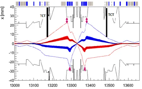
2.1 What limits the *?
In the high luminosity IRs, the triplet quadrupoles define the machine aperture limit for squeezed beams; * is constrained by the beam envelope, the margin between TCT and triplet and the crossing angle (see Figure 2).
During 2011, the * was reduced from 1.5 to 1 m: the first resulted from the interpolation of the aperture measurements at 450 GeV, whilst, for the second one, aperture measurements were done at 3.5 TeV. In 2012, the * was further reduced, thanks to the increase in energy (smaller beams) and the use of tight collimator settings.
An additional reduction of the * would demand for larger aperture triplets.
Figure 2. Beam envelopes (1 for the solid blue and red areas
and 9 for the dashed lines) in the interaction point, considering 1.5 margin at the inner triplets.
2.2 What limits the number and population of bunches?
High bunch population and tight bunch spacing make the beams prone to instabilities related to impedances, i.e. to self-generated fields (called wake field in time domain, beam-coupling impedance in frequency domain): two particles travelling in the same direction interact through the direct space charge effect and through the pipe wall (wall impedance).
In 2012 instabilities have become more critical due to higher bunch intensity and tighter collimators settings. The cures chosen are the use of transverse feedback (‘damper’ that measures the oscillations and sends corrective deflections) and of non-linear magnetic fields (sextupoles, octupoles, beam-beam) that produce a frequency spread among particles and kills coherent motion.
Also, the number and population of bunches is limited by the electron cloud effect, that is the excitation of electrons from the pipe walls (often appearing as an avalanche) when intense, shortly-spaced bunches are passing through the pipe. This was observed in the LHC as soon as the operation with trains started and became worst and worst moving down in bunch spacing from 150, 75, 50 to 25 ns. It is normally associated to vacuum pressure rise, single-bunch and multi-bunch instabilities (leading to incoherent beam size growth) and heat load on the cryogenics. The chosen remedy is the conditioning by beam-induced electron bombardment (“scrubbing”) leading to a progressive reduction of the threshold above which the avalanche occurs.
2.3 Heating damage
Figure 3. Damaged beam screen in an injection protection device.
2.4 Unidentified Falling Objects
The UFOs are thought to be small (10’s mm) dust particles which, falling into the beam, may generate very fast beam losses. If the losses are too high, the beams need to be dumped to avoid a magnet quench. The number of such events in the past years has been [2]:
- 18 beam dumps in 2010 - 17 beam dumps in 2011 - 15 beam dumps in 2012.
A progressive decrease of the UFO rate was observed from the beginning of Run I (a kind of “UFO scrubbing”), but they might become a serious issue for 7 TeV operation, since the losses induced in the magnets by the UFOs will increase by a factor 3 and the tolerable loss will go down by a factor 5 (higher B field): scaling the rate and amplitudes of 2012 one predicts at least one beam dump per day. Furthermore, 10 times higher UFO rate was observed with 25 ns beams.
2.5 Radiation to Electronics
Tunnel electronics which is sensitive to radiation is typically installed in protected areas far away from the beam. Operation in these years has shown that some of the equipment which were supposed to be safe from radiation or located in safe areas, in reality suffer from beam loss induced single event errors (especially quench protection system electronics, power converter and cryogenics PLCs): 74 of these events were observed in 2011 and an identical quantity in 2012 [3]. Despite the increased luminosity production and consequent increase in loss rate, the number of SEE in 2012 was kept low thanks to a series of mitigation actions: equipment relocation (sometimes to surface), additional shielding and more error robust firmware. 2011 Christmas mitigation actions served to reduce the SEUs by almost a factor 4: down to 3 dumps per fb-1. A massive campaign of relocation and shielding is also planned for LS1, which aims at further reducing the number of SEU-induced dumps to less than 0.5 per fb-1.
3
Machine performance in Run I
The performance of the LHC in its first three years of operation have been really impressive, above all if compared with the nominal design parameters (Table 2).
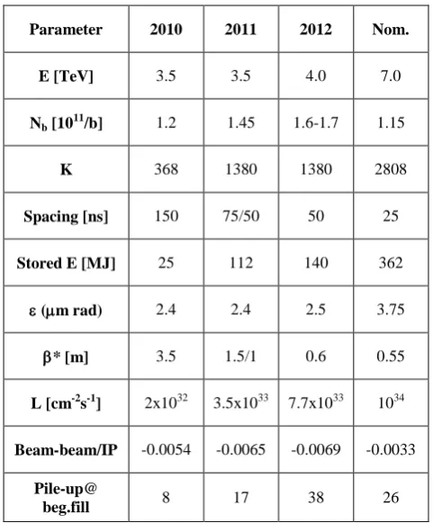
Table 2. Parameters and performance in 2010-2012 (p-p).
Parameter 2010 2011 2012 Nom.
E [TeV] 3.5 3.5 4.0 7.0
Nb [10 11
/b] 1.2 1.45 1.6-1.7 1.15
K 368 1380 1380 2808
Spacing [ns] 150 75/50 50 25
Stored E [MJ] 25 112 140 362
(m rad) 2.4 2.4 2.5 3.75
* [m] 3.5 1.5/1 0.6 0.55
L [cm-2s-1] 2x1032 3.5x1033 7.7x1033 1034
Beam-beam/IP -0.0054 -0.0065 -0.0069 -0.0033
Pile-up@
beg.fill 8 17 38 26
The strategy followed to reach this performance is shown in Figure 4, where the comparison of peak luminosities for proton-proton collisions in 2011 and 2012 is given. In Figure 5, the comparison of the integrated luminosities in three years is also shown, as recorded by CMS [x].
Figure 4. Separation and crossing angles.
beams, with a brightness much higher with respect to the design value.
Figure 5. CMS recorded integrated luminosities in Run I, for p-p collisions.
3.1 Lessons learnt
Many are the important lessons got during LHC Run I, above all about the remarkable reproducibility of the machine, in terms of optics, orbit and tune. A general operational robustness was accompanied by the superb performance of the machine protection (hardware and procedures). The excellent beam lifetime was the result of an excellent vacuum and magnetic field quality, plus the good control of the collective effects and the long range beam-beam perturbation; the head-on beam-beam effect was discovered to be not a limiting factor.
The optics was also remarkably close to the model and corrected to an excellent precision.
Last, but not least, the aperture of the machine was discovered to be better than expected, which allowed reaching and exploiting very low values of *.
4
The LHC upgrade program
The 10 years plan for the LHC foresees three long shut-downs (LS) of the machine for major upgrades, spaced by three years of operation with beam; the first one should be almost 2 years long, while the other two will be only one year long.
What follows is limited to the machine and no reference is done to the upgrade of the experiments; they will however go through major or minor modifications, also to adapt to the modifications of the accelerator.
4.1 LS1
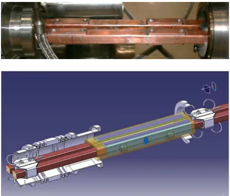
The objective of LS1 [4] is to prepare the machine for 6.5/7 TeV operation in 2015. The actual plan includes: - The consolidation of the 13 kA splices with the approved design of shunt and insulation (open 1695 interconnections and redo ~1500 splices), as shown in details in Figure 6
- The installation of the missing DN200 valves, as completion of the compensatory measures in case of major incident, decided and partly installed in 2009 - The replacement of 15 dipole and 4 quadrupole weak magnets (weak insulation, faulty quench heaters, wrong beam screen, missing correctors)
- The consolidation of faulty circuits
- The R2E mitigation actions, with relocation of electronics in 3 points
- The installation of collimators with integrated button BPMs (tertiary collimators and a few secondary collimators).
All these activities will be performed in about 20 months, after which the machine should be able to work at 7 TeV (most probably initially 6.5, to have a reduced number of training quenches), with the nominal luminosity of 1034 cm-2s-1.
Figure 6. Two details of the consolidation of the 13 kA splices: shunts installed across each segment of copper bar (on top) and new insulation ox around both bus-bars (on the bottom).
4.2 LS2
The second long shut-down will be mainly devoted to a major upgrade of the injectors (LINAC4, 2GeV PS Booster, SPS coating). Nonetheless, many interventions will be performed on the LHC too:
- The dispersion suppressor, so-called cryo-collimators with a compact 11 T magnet, in one experimental point, to avoid off-momentum protons on SC dipoles
- Vertical SC links in point 1 and 5 (to feed the inner triplet and the stand-alone magnets), to definitely overcome the radiation issue
- A new cryogenic installation at point 4, with the separation between SC magnets and RF cavities cooling circuit
- Improved triplet cooling - Some beam diagnostics - Some collimators.
4.3 LS3
1.2 km of the LHC tunnel will be modified during LS3, with new triplet magnets and separation-recombination dipoles plus matching section quadrupoles, with new cryogenics and vertical links for all new elements. Also, the crab cavities should be installed, to cope with the problem of the crossing angle, and new instrumentation and collimators. The declared objective is to push the performance above the ultimate (5 x1034 cm-2s-1 or more) with an integrated luminosity of 3000 fb-1 by 10-12 years.
5
Conclusions
The progress in the performance of the LHC has been breath-taking.
The LHC is performing incredibly well (even better than expected) and this is possible thanks to the quality of the design, construction and installation and to the thorough preparation in the injectors which are delivering beams well beyond nominal parameters
A solid upgrade program is in a very mature state, even if the final parameters will depend on the capacity of the experiments to manage pile-up.
6
Acknowledgements
The author would like to thank G. Arduini, J. Wenninger and L. Rossi for providing material for this work.
References
1. O. Bruning et al., LHC Design Report, Geneva: CERN, 2004. - 548 p.
2. T. Baer, private communication.
3. LHC Post-mortem database, ihttp://lhc-postmortem.web.cern.ch/lhc-postmortem/
4. F. Bordry et al., The First Long Shutdown (LS1) of the LHC, presented in IPAC 2013, Shanghai, June 2013.