344 | P a g e
AN ALTERNATIVE METHOD TO GENERATE
RECIPROCATING MOTION
Tribhuwan Singh
1, Satyendra Chaturvedi
2, Shahazad Ali
1,2
Assistant Professor
Department of Mechanical Engineering,
IIMT College of Engineering, Greater Noida , UP, (India)
3
A
ssistant Professor
Department of Mechanical Engineering, Noida Institute of
Engg. & Technology, Greater Noida, UP, (India)
ABSTRACT
Engine is the main power source of Automobiles, where combustion takes place & produces heat which
converts into mechanical energy. We know IC-Engines are used in Automobiles, Aero-planes etc. But
incomplete combustion produces some harmful gasses like NOx, which is main cause of air pollution. Modern
Science & Technology has been taken many positive steps for emission control. Like using CNGs & LPGs
instead of petrol & diesel. Now technology brings Electrical bikes, scooters & cars. The battery of electrical
vehicle can charge easily like mobile. They have less running cost & 100% emission free. But they have very
less load carrying capacity & not suitable for long run. So basically we have to prefer Engines for more power
& more running capacity. Here a new mechanism is introduced which has more load carrying & running
capacity than electrical vehicles but makes zero emission or pollution.
In this paper a new engine which will work on the principle of electromagnetism is discussed. In this solenoid
coil with iron as a piston cylinder arrangement is used with some electronic circuit to control the movement of
solenoid. And assemblies are made for engine arrangement.
I. INTRODUCTION
Like conventional engines this system also has cylinder, piston (without piston rings), connecting rod, crank
shaft. There is no inlet & exhaust valve or ports & no spark-plug also. In this system we are using 4 Solenoids.
Solenoid behaves like a magnet when electricity supplied to it. These solenoids with iron core works as a piston
cylinder arrangement as in IC engines. When current is supplied to solenoid coil, the iron core inside the coil
start moving.
This moves of iron core is used as piston movement, and with some modification in crankshaft and connecting
rod, this is used in engine assembly. For the movement of coils a timer circuit is used. This circuit contains a
conducting disk, A DC motor and a rectifier circuit. We can also control its speed by using an fan regulator.
This paper is all about an engine which will work on electric supply. This engine can work on both type of
345 | P a g e
II. OBJECTIVE
1. The main objective of this paper is to form a mechanism which work as an IC engine without using any
fuel.
2. This system works on the principle of electromagnetism and the system is powered by electromagnetic coil.
3. This system is fully emission free i.e. it doesn’t produce any harmful gases. And that is our sole purpose.
III. LITERATURE REVIEW
According to the paper “Design and development of a new electromagnetic prime mover solenoid powered
engine preliminary design”, published in Control System, Computing and Engineering (ICCSCE), 2012 IEEE
International Conference. It stated that, The applications of electromagnetic prime mover devices are becoming
more extensive as future technological developments are moving towards sustainable environment. From
various types of electromagnetic prime mover devices, the most commonly used device is electric motor.
However, this device has some major issues such as complex maintenance processes after catastrophic failure,
complex/expensive controllers, and declining performance from the dependency of limited raw materials i.e.
permanent magnets. These problems are mostly associated with the convenience in operation and certain
problems are only applicable to certain types of electric motor. Due to these issues, the authors have developed a
new electromagnetic prime mover design to replace the existing electric motor. This new prime mover is
designed based on the solenoid concept and the internal combustion engine working mechanisms. In this paper,
the authors are introducing a new electromagnetic prime mover design known as Solenoid
Powered Engine (SPE). The paper describes the SPE conceptual design, mechanical components and combined
electrical/electronic components.
Also the paper published in Power and Energy Conference, 2008. PECon 2008. IEEE 2nd International states
that, Designing an electric vehicle (EV) using electric motor as its prime mover is very common. However,
incorporating the electric motor to the overall EV design is relatively complex. The latest layout design of an
EV requires a complex controller to govern the whole system especially the electric motors. Due to this
complexity, the authors have developed an alternative electromagnetic prime mover for EV to replace the
existing electric motor. This new prime mover is designed based on the solenoid concept and the internal
combustion engine (ICE) working mechanisms. In this paper, the authors are introducing a new electromagnetic
prime mover known as solenoid powered engine (SPE).
IV. METHODOLOGY
In this system we have used 4 ac solenoid coils as an electromagnetic coil. These coils are working as cylinder
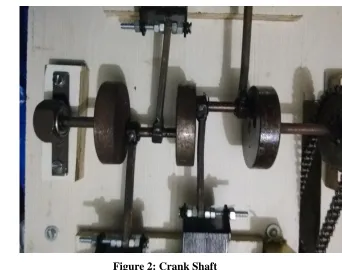
piston arrangement. This coil arrangement is further supported by a designed crankshaft containing a power
transmitting disk and gear arrangement with bearings.
The design of this system is derived from the In-line 4-cylinder engine. In this we have used 2 coils at one side
346 | P a g e
V. COMPONENTS REQUIRED
1. 4- Solenoid coil (AC coil)
2. Bearing
3. Crankshaft (designed)
4. Chain and sprocket
5. Wheel
6. Wheel shaft
7. Dc Timer circuit
8. Wire
9. Body frame
Figure 1: Solenoid Coil
Different components are assembled on a self constructed model as per drawing
.
347 | P a g e
VI.
ELECTRONIC CIRCUIT
A rectifier is an electrical device that converts alternating current (AC), which periodically reverses direction, to
direct current (DC), which flows in only one direction. The process is known as rectification. Physically,
rectifiers take a number of forms, including vacuum tube diodes, mercury-arc valves, copper and selenium
oxide rectifiers, semiconductor diodes, silicon-controlled rectifiers and other silicon-based semiconductor
switches. Historically, even synchronous electromechanical switches and motors have been used. Early radio
receivers, called crystal radios, used a "cat's whisker" of fine wire pressing on a crystal of galena (lead sulfide)
to serve as a point-contact rectifier or "crystal detector".
Rectifiers have many uses, but are often found serving as components of DC power supplies and high-voltage
direct current power transmission systems. Rectification may serve in roles other than to generate direct current
for use as a source of power. As noted, detectors of radio signals serve as rectifiers. In gas heating systems
flame rectification is used to detect presence of a flame.
Because of the alternating nature of the input AC sine wave, the process of rectification alone produces a DC
current that, though unidirectional, consists of pulses of current. Many applications of rectifiers, such as power
supplies for radio, television and computer equipment, require a steady constant DC current (as would be
produced by a battery). In these applications the output of the rectifier is smoothed by an electronic filter
(usually a capacitor) to produce a steady current.
More complex circuitry that performs the opposite function, converting DC to AC, is called an inverter.
VII. WORKING PRINCIPLE
A common tractive electromagnet is a uniformly-wound solenoid and plunger. The solenoid is a coil of wire,
and the plunger is made of a material such as soft iron. Applying a current to the solenoid applies a force to the
plunger and may make it move. The plunger stops moving when the forces on it are balanced. For example, the
forces are balanced when the plunger is centered in the solenoid.
The maximum uniform pull happens when one end of the plunger is at the middle of the solenoid. An
approximation for the force F is
348 | P a g e
The maximum pull is increased when a magnetic stop is inserted into the solenoid. The stop becomes a magnet
that will attract the plunger, but it adds little to the solenoid pull when the plunger is far away, but dramatically
increases the pull when they are close. An approximation for the pull P is
Here la is the distance between the end of the stop and the end of the plunger. The additional constant C1 for
units of inches, pounds, and amperes with slender solenoids is about 2660. The second term within the bracket
represents the same force as the stop-less solenoid above; the first term represents the attraction between the
stop and the plunger.
VIII. RESULT AND DISCUSSIO
Work carried out on this project gives out the result as:
1. We are able to make a working model of electromagnetic engine. This works on principle of
electromagnetism.
2. A fully emission free engine mechanism is developed by the arrangement of 4 electromagnetic coil with a
designed crankshaft.
3. This engine has less efficiency then conventional IC engines.
4. Its speed can be controlled by a regulator.
This system needs more development for its use in near future. Further improvement is needed for
increasing its efficiency and its use ability in daily life.
349 | P a g e
IX. CONCLUSION
Sooner or later, maybe - in the nearest future, this electromagnetic engine would be realistic one. The most
important thing mechanism is now known, its only need a goo d and improved arrangement for the
betterment of this system.
The two most important thing is to increase its efficiency and its compact assembling of its part so that
its use in machines. Also now it will be only applicable to places where low power is re quired with
smooth running. Also in near future it will get tough competition to electric motors.
For further improvements important area is its input to output ratio and its coils design for smooth
running. This project is an simple working model of future electromagnetic engine.
X. FUTURE SCOPE
1. The main advantage of this project is that it is fully emission free. It doesn’t produce any pollution.
2. This engine mechanism is very useful in future when there is scarcity of fossil fuels.
3. This engine mechanism will be run by both AC and DC currents, by simply modifying the electromagnetic
coils.
4.
This mechanism will be good replacement to IC engines in very future when pollution is high and there isless availability of fossil fuels.
XI. REFERENCES
1. “Studies on electromagnetic engines”, by Amarnath, jayprakesh, Balaji, International journl of development
research.
2. “A research in the application of permanent magnets and solenoids to the planar Maglev system design”:
Conference Paper · May 2003, Magnetic conference 2003 alifornia.
3. “Design and development of a new electromagnetic prime mover solenoid powered engine preliminary
design”, by Syed Zainal Abidin , Kamarul Bahrin ; Department of Electrical Power Universiti Tenaga
Nasional Selangor, Malaysia.
4. Guarnieri, M.; , "When Cars Went Electric, Part One [Historical]," Industrial Electronics Magazine, IEEE ,