MODELLING, SIMULATION AND PERFORMANCE
OF QUADROCOPTER USING MATLAB SOFTWARE
Ashwin Rameshrao Garle
1, Prof. Dr. B. E. Kushare
21, 2
Department of Electrical Engineering
K. K. Wagh Institute of Engg. Education & Research, Nashik, Maharashtra, (India)
ABSTRACT
The quadrocopter is one of the most complex flying machines. Its complexity is due to the versatility and maneuverability to perform many types of tasks. Quadrocopter is a unique type of aerial vehicle which has the vertical take-off and landing (VTOL) ability. This work is aimed to study the mathematical modelling of quadrocopter and the performance of quadrocopter has been demonstrated by simulation using versatile simulation package, MATLAB/Simulink. The dynamic model of the quadrocopter is obtained via a Lagrange approach. The proposed controller is based on Lyapunov analysis using a nested saturation algorithm. The proposed controller is compared with PID controller using MATLAB/SIMULINK. PID controller exist more oscillations than in the nested saturations control algorithm. Simulation results show that the controller is able to perform the tasks of taking off, hovering, and landing.
Keywords: Aircraft Control, Aircraft Dynamics, Helicopter Control, Lyapunov Methods, Real-Time
Systems, Recursive Control Algorithms.
I. INTRODUCTION
1.1 Overview of Quadrocopter
Since the beginning of the 20th century, many research efforts have been done to create effective flying
machines with improved performance and capabilities. The use of Aerial Vehicles for military, scientific and
civilian sectors are increasing drastically in recent years. UAVs (Unmanned Aerial Vehicles) have clear
advantages such as higher manoeuvrability, lower cost, decreased radar signature, strength, as well as decreased
risk for human life. These advantages lead the use of these vehicles in many applications from military
operations to civilian tasks, and extensive research are carried out in many laboratories. Currently, there are
various commercial and experimental aerial vehicles of various sizes available, and many more autonomous
VTOL (VERTICAL TAKE OFF & LANDING) vehicles are being developed at universities, research centres,
and by hobbyists. The quadrocopter has been used for many applications and research studies, as well. The
studies in quadrocopter modelling and control increased rapidly in recent years [1].
Quadrocopter is a type of helicopter with four lift-generating propellers mounted on motors. Two of the motors
generate thrust by spinning their propellers clockwise and other two counter-clockwise. Control of the machine
can be achieved by varying the relative speed of the propellers. Due to the availability of high-speed brush less
motor, inertial measurement units based on MEMS(Micro Electro Mechanical Sensors) technology and high
power to weight ratio ( 150 W/Kg) Li-polymer batteries, quadrocopter can now be designed and fabricated but
In contrast to a classical helicopter with main and tail rotors, a quadrocopter is propelled by four horizontal
rotors directly attached to the airframe. But the four propellers are not the same, and they are divided in two
pairs that contain two pusher blades and two pullers blades, which work in a contra-rotation manner. The
different motions of a quadrocopter are generated by varying the speed of four rotors as well as changing the
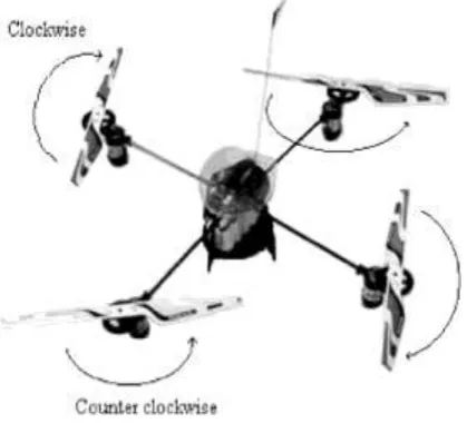
thrust of each blade. As shown in Fig.1.1 The quadrocopter consists of four motors on which propellers are
mounted. These motors are arranged at the corners of a X-shaped frame, where all the arms make an angle of 90
degrees with one another. As shown in Figure 1.1, two of the rotors or propellers spin in one direction and the
other in the opposite direction. Each spinning propeller generates vertically upward lifting force. All the motion
of machine is a consequence of this force. Lifting forces generated by the spinning propeller and the weight, are
responsible for all the motion of body, as the external effects such as air friction, wind pressure etc. have been
neglected. The design of quadrocopter motors and propellers is assumed to be such that these thrust forces
always act perpendicular to the plane of propellers and therefore plane of quadrocopter [2]. The center of mass
of machine is located at the centre of the quadrocopter and the weight force acts at this point.
One of the limiting factors that prevents further implementation of the helicopters into applications, is the way it
moves. It needs to tilt along the desired direction of motion. By doing this it can have necessary acceleration
towards that direction. But tilting has the undesired effect of moving the on-board camera’s direction of view.
This becomes an issue for surveillance and other vision based tasks. There has been considerable innovation in
the sensors that are used to control the quadrocopter as well. Modern MEMS (Micro Electro Mechanical
Sensors) technology makes it easier to add more sensors on a small quadrocopter as the space and weight
constraints can be stringent. Sensors including basic IMUs (Inertial Measurement Units), GPS (Global Position
System) modules.
Due to some unique abilities of the quadrocopter such as high manoeuvrability, small size, and easy control mini
rotorcrafts are finding many applications. The most significant of them would have to be search-and-rescue and
emergency response. Other major applications of quadrocopters are in homeland security, military surveillance,
and search and destroy. Miniaturization of quadrocopter has enabled them to be used for border patrol and
surveillance. Quadrocopter also have potential applications in other areas like earth sciences where they can be
used to study climate change, glacier dynamics, and volcanic activity or for atmospheric sampling. [3].
As the number of applications is significantly increasing, current research goals have created a serious need for
specialized air vehicles, able to:
1.
Pose certain flight advantages, and2.
Cope up with specific mission requirements.At the same time these air vehicles must have significant on-board processing power for ensuring that complex
and demanding calculations can be performed uninterruptedly. This need arises from the fact that the system
must be able to cope with harsh or special environmental conditions (such as high wing perturbations or
cramped spaces), which imposes the necessity for complex control laws, taking into account the dynamics of the
vehicle’s environment and constraints.
The quadrocopter is one of the most complex flying machines. Its complexity is due to the versatility and
maneuverability to perform many types of tasks. The classical helicopter is conventionally equipped with a main
rotor and a tail rotor. However, other types of helicopters exist, including the twin rotor or tandem helicopter
and rear motors rotate counter clockwise while the other two rotate clockwise, gyroscopic effects and
aerodynamic torques tend to cancel in trimmed flight.
Figure 1.1: The Schematic of Quadrocopter
This quadrocopter does not have a swash plate. In fact it does not need any blade pitch control. The collective
input (or throttle input) is the sum of the thrusts of each motor. Pitch movement is obtained by increasing
/reducing the speed of the rear motor while reducing /increasing the speed of the front motor.
The roll movement is obtained similarly using the lateral motors. The yaw movement is obtained by increasing
/decreasing the speed of the front and rear motors while decreasing /increasing the speed of the lateral motors.
This should be done while keeping the total thrust constant .In view of its configuration, the quadrocopter has
some simi-larities with planar vertical take-off and landing (PVTOL) aircraft.
The quadrocopter under consideration consists of a rigid cross frame equipped with four rotors as shown in Fig.
1.1. The up (down) motion is achieved by increasing (decreasing) the total thrust while maintaining an equal
individual thrust. The forward/backward, left/right and the yaw motions are achieved through a differential
con-trol strategy of the thrust generated by each rotor. In order to avoid the yaw drift due to the reactive torques, the
four rotor aircraft is configured such that the set of rotors (right-left) rotates clockwise and the set of rotors
(front-rear) rotates counter clockwise. The forward/backward, left/right and the yaw motions are achieved
through a differential control strategy of the thrust generated by each rotor. There is no change in the direction
of rotation of the rotors [6].
Major comparative point with respect to a traditional helicopter can be given as follows:
In traditional helicopters, the yaw motion, due to the reactive torque of the main rotor, is compensated by the
torque produced by the tail rotor. The energy spent on the tail rotor makes no contribution to the upward thrust
of the helicopter. Comparatively, in the four rotor design, if the four rotors rotate at the same speed, there will be
no yaw motion since the reactive torques are cancelled out, as one pair of rotors rotates in the opposite direction
of the other pair. In this case, all of the energy spent on the four rotors contributes to generate the upward thrust.
The same upward thrust generated by a single rotor in traditional helicopters can be generated by four smaller
rotors for the quad rotor; and the fact of using rotors with smaller size helps to reduce the induced mechanical
vibrations comparatively to a single large main rotor. On the other hand, traditional helicopters have somewhat
complicated mechanisms for achieving controlled flight, while for the four rotor mini rotor craft, controlled
flight is achieved easily by differential thrust control of the four rotors[7].
1.2Aim of the Work
The objective of this project is to study the mathematical modelling of the quadrocopter. The dynamic model of
the four-rotor rotorcraft is obtained via a Lagrange approach. Pro-posed controller is based on Lyapunov
analysis using a nested saturation algorithm. The proposed controller is compared with PD controller using
MATLAB/SIMULINK.PID controller exist more oscillations than in the nested saturations control
algorithm.Sim-ulation results show that the proposed controller is able to perform the tasks of taking off,
hovering, and landing and propose nested saturations control algorithm exist less oscillations than PID
controller.
This project simulate and perform analysis of quadrocopter on three axis x, y, z using MATLAB/SIMULINK
simulation package. It also simulate and perform analysis of quadrocopter with trajectory following various
paths along X-axis,Y-axis,Z-axis.
1.3 Scope of the Work
This work is divided into three stages. This is to ensure that the project is conducted within its intended
boundary and is heading to the right direction to achieve its objectives:
The first stage is to study working principle of the quadrocopter.
Secondly, mathematical modeling of the quadrocopter being studied.
The third stage of the project is to analyze on the comparative performance of the quadrocopter between proposed controller based on Lyapunov analysis using a nested saturation algorithm and PID controllerusing MATLAB/SIMULINK. with respect to commanded input along x-axis, y-axis and z-axis. Performance of
the quadrocopter is also analyzed from the trajectory plotted by quadrocopter against commanded inputs along
x-axis,y-axis,z-axis based on the MATLAB/SIMULINK simulation results.
1.4 Thesis Outline
This section will give an outlines of the structure of the thesis. The following is an explaination for each chapter.
Background of Control techniques for quadrocopter.
Chapter 2 discusses a mathematical modelling of quadrocopter .
Chapter 3 gives the comparative analysis and simulated output of quadrocopter for translational parameters
along x-axis, y-axis and z-axis using MATLAB/SIMULINK. It also shows the performance and analysis of
quadrocopter for trajectory.
Chapter 4 presents the conclusion.
II.STUDY OF MATHEMATICAL MODELLING FOR QUADROCOPTER
The purpose of deriving a mathematical model for quadrocopter is to assist in developing controllers for
physical mini rotorcrafts. The general method to design a control system is to calculate the dynamic model of
the system. The dynamic model of a system is a mathematical equation that comprises of all the forces that can
act on the system at a given time. A conventional quadrocopter is an under actuated aircraft with four rotors that
have fixed position with respect to the aircraft body frame.
2.1 Assumptions
The quadrocopter structure is rigid and its deformation characteristics will be disregarded.
The quadrocopter structure is symmetrical and material inconsistencies will be disregarded.
The propellers are rigid and deflections will be ignored.
The cross products of the inertia matrix can be neglected.
The ground effect is neglected.
Small body forces are ignored, because they are generally of a much smaller magnitude than the principal
control inputs u and τ.
Force-balance analysis of quadrocopter is carried out in steady state conditions only. Turbulent conditions
are ignored.
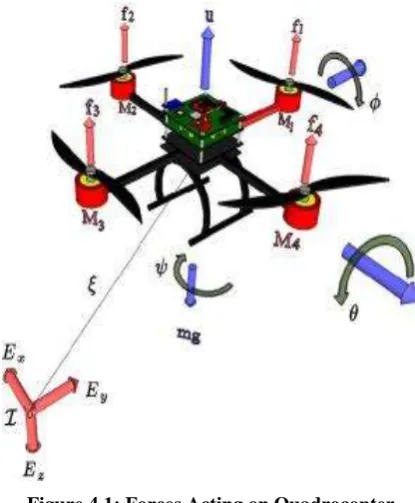
Rigid body representation of the quadrocopter is given in Fig. 1. Body fixed frame is assumed to be at the
Centre of gravity of the four rotor where z axis is pointing downwards. According to the Euler’s angle
representation, angles of rotation about the aircraft’s Centre of mass in x, y and z axes are defined respectively
as roll (φ), pitch (θ) and yaw (ψ). The earth’s gravitational force is assumed to be constant and in downwards direction.
The generalized coordinates of the mini rotorcraft are q = (x, y, z, ψ, θ, φ) where ξ
Figure 4.1: Forces Acting on Quadrocopter
= (x, y, z) denotes the position of the centre of mass of the mini rotorcraft relative to a fixed inertial frame I, and
η= (ψ, θ, φ) are the Euler angles, ψ is the yaw angle around the z-axis, θ is the pitch angle around the modified
y-axis, and φ is the roll angle around the modified x-axis, which represent the orientation of the rotorcraft. The translational kinetic energy of the rotorcraft is
Ttrans = m.ξ/2 T .ξ (4.1)
Where m denotes the mass of the rotorcraft. The rotational kinetic energy is
Trot= 2.ηT .J.η (4.2)
The matrix J acts as the inertia matrix for the full- rotational kinetic energy of the rotorcraft expressed directly in
U = mgz ( 4.3)
z is the rotorcraft altitude, ω is the angular velocity, I is the inertia matrix, and g is the acceleration due to gravity. The angular velocity vector ω resolved in the body fixed frame is related to the generalized velocities η (in the region where the Euler angles are valid) by means of the kinematic relationship
The Lagrangian is
L(q, q′) = Ttrans + Trot – U (4.4)
Small body forces may be ignored because they are generally of much smaller magnitude than the principal
control inputs (u)
u = f1 + f2 + f3 + f4 (4.5)
The thrust of rotor i is equal to f = K.ω2. While, the rotation speeds of the motors are described by ω, the rotor thrust force is also equal to f = K.ω2, where parameter K is a constant namely the push factor.
III. SIMULINK MODEL AND ITS COMPARATIVE PERFORMANCE ANALYSIS
The main goal is to achieve a stable flight of the quadrocopter, this is done using two control strategies: a linear
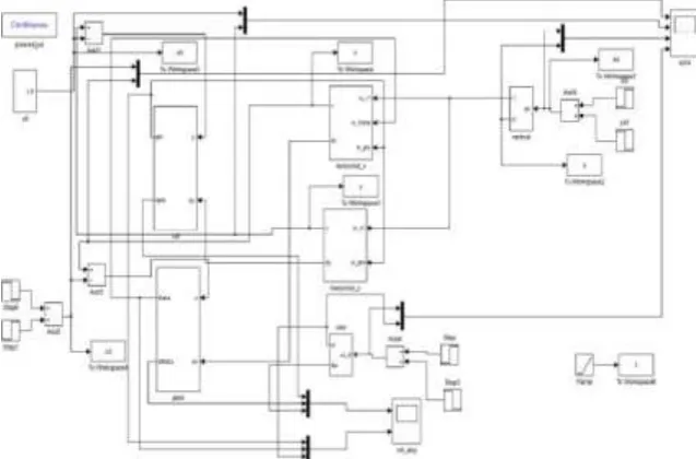
PID control and nonlinear nested saturations control.This chapter details MATLAB Simulink model of
quadrocopter. Figure 5.1 below shows the Simulink model for quadrocopter using nested saturation control
algorithm
Figure 5.1: Simulink Model for Quadrocopter Using Nested Saturation Control Algorithm
Figure 5.3 shows the output of nested saturation control algorithm along y-axis.
Figure 5.4 shows the output of nested saturation control algorithm along z-axis.
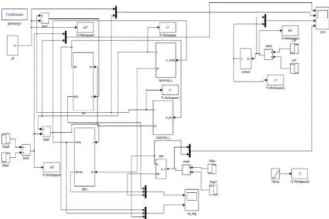
3.1 PID Controller
Figure 5.5 above shows the Simulink model for quadrocopter using PID Controller
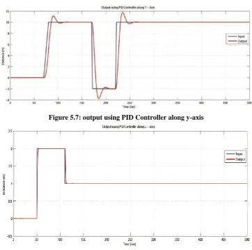
Figure 5.7: output using PID Controller along y-axis
Figure 5.8: output using PID Controller along z-axis
IV.CONCLUSION
In this report, proposed a control algorithm for a quadrocopter. The dynamic model of the quadrocopter
obtained via a Lagrange approach is studied and the proposed control algorithm based on Lyapunov analysis
using nested saturations also been implemented using MATLAB/SIMULINK software.
The proposed controller has been successfully applied using MATLAB/SIMULINK software. Quadrocopter
follows the applied/commanded input very closely. From the obtained results of three translational moments
along x-axis, y-axis and z-axis, it can be concluded that the controller performs satisfactorily.
The proposed control algorithm in this report is easy to understand and simple implement. From performance
analysis it can be conclude that the response is almost similar for both controllers (i.e Nested Saturation Control
Algorithm and PID Controller), but the PID controller exist more oscillation than in the nested saturations
control algorithm. It is also observed that PID controller output takes more settling time as compared to output
of nested saturation control algorithm.
Simulation results shows that the proposed controller is able to perform the tasks of taking off, hovering, landing
and it offers more stable flight as it has less oscillations compared to PID controller .
The results show that
MATLAB paired with Simulink is a good simulation tool for modelling and to analyse quadrocopter
REFERENCES
[1] Karl E. Wenzel, Andreas Masselli and Andreas Zell ”Visual Tracking and Following of a Quadrocopter by
another Quadrocopter ” 2012 IEEE/RSJ International Conference on Intelligent Robots and Systems,
October 7-12, 2012.
[2] ShoheiNoda ,Shozi Machida and Hun-ok Lim” Mechanism and Control of Four Rotor Flying Robot ” 11th
International Conference on Control, Automation and Systems ,Oct. 26-29, 2011.
[3] Qiang Zhan, Junqing Wang, Xi Xi,” Control System Design and Experiments of a Quadrotor ” Proceedings
of the 2012 IEEE International Conference on Robotics and Biomimetic , December 11-14, 2012.
[4] Buddy Michini, Josh Redding, N. Kemal Ure, Mark Cutler and Jonathan P. How ” Design and Flight
Testing of an Autonomous Variable-Pitch Quad rotor ”, IEEE International Conference on Robotics and
Automation, May 9-13, 2011.
[5] Vahid Khorani and Alireza Mohammad Shahri ” The True Role of Accelerometers in Quadrotor’s Inertial
Navigation System ” Proceeding of the 2013 RSIIISM International Conference on Robotics and
Mechatronics ,February 13-15, 2013.
[6] Pedro Castillo, Student Member, IEEE, Alejandro Dzul , Member, IEEE, and Rogelio Lozano, Member,
IEEE” Real-Time Stabilization and Tracking of a Four-Rotor Mini Rotorcraft ”, IEEE Transactions On Control Systems Technology, VOL. 12, NO. 4, July 2004.
[7] Shweta Gupte, Paul Infant Teenu Mohandas , James M. Conrad ”A Survey of Quad rotor Unmanned Aerial
Vehicles” IEEE-978-1-4673-1375- 9/12/2012, Dec-2012.
[8] Rodrigo Kuntz Rangel, Karl Heinz Kienitz, Mauricio Pazini Brandao ”Development of a Multi-Purpose