R E S E A R C H
Open Access
The inflection point: a torque reference for
lingual bracket positioning on the palatal
surface curvature of the maxillary central
incisor
Abdel Hadi Kanj
1*, Joseph Bouserhal
1,2,3, Essam Osman
4and Ahmed Abdel Moneim El Sayed
1Abstract
Background:Contrary to buccal orthodontics, lingual orthodontics has no reference for vertical bracket positioning on the maxillary central incisor. The aim of this study was to provide a reference point in relation to torque for lingual bracket positioning on the palatal surface curvature (PSC) of the maxillary central incisor.
Methods:Cone beam computed tomography (CBCT) radiographs of 50 right maxillary central incisors from archives of a dental radiographic center were transferred to Photoshop, where their PSC was traced using pen-tool. The PSC torque angle values of the incisors were calculated in Excel using cubic poly-Bezier curves at 0.5-mm increments and at the inflection point of PSC. Descriptive statistics for the torque angle values of the increments and for the inflection point for the 50 incisors were then calculated. One-way ANOVA test was used to detect systematic differences between the increments, and Tukey test was used post-hoc.
Results:For all incisors, increments incisal to inflection point exhibited progressive decrease in torque angle values from the first-calculated increment to inflection point while increments cervical to inflection point exhibited progressive increase from inflection point to last-calculated increment. Mean torque angle values of all the increments and inflection point showed high standard deviations and vast range of values. One-way ANOVA test was highly statistically significant (p< 0.0001) and most pairwise comparisons of the increments using Tukey test were significant.
Conclusions:Inflection point can be used as a reference for bracket positioning on PSC. Cervically oriented shifts in vertical bracket position cause crown labial/root palatal movement cervical to inflection point and crown palatal/root labial movement incisal to it. A scientific mathematical justification for customized bracket torque prescriptions on PSC of maxillary central incisor was also provided.
Keywords:Bracket positioning, Lingual orthodontics, Maxillary central incisor, Torque
Background
The torque of a certain crown site can be assessed by viewing the proximal tooth aspect and then determining the inclination of the tangent at that site [1–13]. Conse-quently, each bracket site on a tooth will have an associ-ated torque angle value (TorqueAngleValue) determined by the
tangent’s inclination at that site. The difference in torque between two bracket positions can be found by subtract-ing their associated TorqueAngleValues [6–13]. The effect of vertical bracket position on torque in labial/buccal or-thodontics has been discussed thoroughly in the litera-ture [6–13] compared to a single study in lingual orthodontics [2]. Yet that lingual study used only four different vertical bracket positions to investigate that ef-fect instead of using 0.5 mm or 1 mm tooth increments, akin to the studies of the labial/buccal orthodontics [6– 8, 10–13]. In their turn, Kurz et al. [1] calculated the
* Correspondence:[email protected] 1
Department of Developmental Sciences, Division of Orthodontics, Faculty of Dentistry, Beirut Arab University (BAU), Beirut Campus, Main Building, 1st Floor, Tareek El Jadida P.O. Box 11-5020 Riad El Solh 11072809, Beirut, Lebanon
Full list of author information is available at the end of the article
TorqueAngleValue of only one bracket site on the lingual sur-faces of a set of maxillary and mandibular dentition, while Bryant et al. [4] with a mathematical equation of a parametric survival model could only calculate the max-imum slope found at the inflection point of the palatal surface curvature (PSC) of the maxillary central incisor. The inflection point of a mathematical function is the point where the curvature of that function changes from convex to concave or vice versa [14].
TorqueAngleValue calculation is generally accomplished by drawing tangents directly on the crown [8, 9]. Miethke pointed out that this method“is more or less subjective depending on the crown curvature” [8]. The error in angle measurement which can occur upon the use of drawn tangents to assess lingual surface curvature can exceed 4° [2], which calls for more accurate mathemat-ical methods of angle measurement. The pen-tool in Adobe Photoshop Creative Cloud 2013 (Adobe Systems Inc., San Francisco, CA) can create cubic Bezier curves, which are parametric mathematical equations where the tangent at any point on these curves could be calculated
by using the curve’s first derivative [15]. A cubic Bezier curve is formed by four control points and mathematic-ally it is represented by two equations [16]. The two equations could be found by substituting the coordinates of the four control points in the mathematical formula of the cubic Bezier curve [16]. The initial and terminal control points of the cubic Bezier curve lie on the curve and are always its endpoints while the other two inter-mediate control points which determine its curvature do not generally lie on the curve [16].
Contrary to lingual orthodontics, conventional labial orthodontics has a reference point for bracket position-ing reflected in the long axis point [17]. As there is no reference in lingual orthodontics for bracket positioning on PSC, the aim of this study was to find if the inflection point of PSC can be used as a torque reference for lin-gual bracket positioning (the inflection point of PSC is the anatomical landmark where the intersection between the convex and concave portions of PSC occurs). The use of cone beam computed tomography (CBCT) to cal-culate the TorqueAngleValues on the labial and buccal surface
curvatures were made previously in two studies [12,13]. To our knowledge, no study has been done using CBCT to assess the PSC of the maxillary central incisor through cubic poly-Bezier curves in Photoshop.
Methods
Ethical committee approval was obtained from the uni-versity’s ethical board before beginning the study (pre--approval code: 2016H-0040-D-M-0155). To fulfill the aim of the study, 50 right maxillary central incisors (RMCI) were selected from CBCT archives of a dental radiographic center and then the TorqueAngleValues of their Photoshop-traced PSC were calculated at 0.5-mm incre-ments and at the inflection point using the first
derivative of their cubic poly-Bezier curve. A total of 50 CBCT radiographs containing both jaws were selected randomly from the archives of a radiographic center in a private office. Those radiographs were made for non-orthodontic reasons and were taken by a Kodak 9500C Cone Beam 3D machine (Kodak Dental Systems, Carestream Health Inc., Rochester, NY) at 10 mA, 80 KV and an exposure time of 10.8 s with a voxel dimen-sion of 300μm. The inclusion/exclusion criteria for the selection of each CBCT radiograph is detailed below.
Inclusion criteria
– Radiographs should belong to individuals aged between 15 and 30.
– The absence of inter-incisal contact on the palatal surface of the RMCI on radiograph. Contact of the lower incisors on the PSC of the RMCI would not allow proper tracing of PSC.
– RMCI presenting palatal surface and incisal edge integrity on radiograph.
Exclusion criteria
– Intra-oral presence of metal or amalgam restorations shown in radiograph.
– Intra-oral presence of labial or lingual brackets in radiograph.
– RMCI with attrition or caries or a dilacerated root in radiograph.
The manipulation of each RMCI followed the proce-dures detailed below (all proceproce-dures were made by one orthodontist):
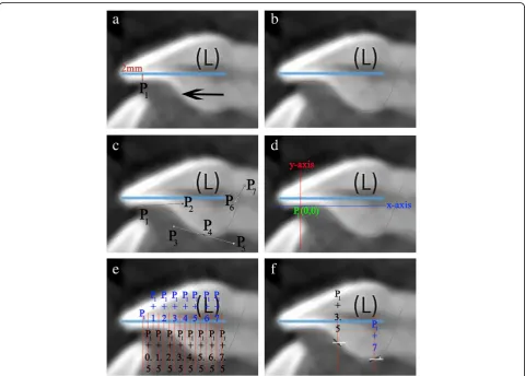
1. Using CS 3D Imaging Software 3.1.9 (Carestream Health, Rochester, NY), the axial slice in“Oblique Slicing”tab was selected and the indicator which represented the sagittal plane was oriented with the labio-palatal axis of the RMCI (Fig.1a). In the sagittal slice, a line with a known measurement (calibration line) was drawn that was used later for calibration (Fig.1b). A screenshot image of the workspace at double magnification was made and then the TIFF image was opened with Photoshop.
2. In Photoshop, the scale from pixels to millimeter was calibrated using the calibration line. The long axis of the crown was then drawn in Photoshop (Fig.1c). The long axis of the crown was defined similarly to Bryant et al. [4] and van Loenen et al. [9] as a line drawn from the incisal edge of the incisor to the midpoint of the line joining the palatal and labial CEJ. The image was then rotated until the long axis of the crown became horizontal
Fig. 3x1CP, x2CP, x3CP, and x4CPstand respectively for thexcoordinate value of the first, second, third, and fourth control points of the respective cubic poly-Bezier curve (first or second). y1CP, y2CP, y3CP, and y4CPstand respectively for theycoordinate value of the first, second, third, and fourth control points of the respective cubic poly-Bezier curve. The parameter tin all the equations below lies between 0≤t≤1. The first and second equations are the equations of thexand ycomponents of the cubic Bezier curve respectively, while the third and fourth equations are their first derivatives, respectively, and the fifth and sixth equations are the second derivatives. The position of the inflection points of a parametric cubic Bezier curve are among the solutions of the equation: B′(t)XB″(t) = B′x(t)•B″ y(t)‐B′y(t)•B″x(t), where B′(t) and B″(t) stand for the first and second derivative vectors, respectively, of Bezier curve andXstands for the
(parallel to Photoshop’sx-axis) (Fig.1d). This rotation allows superimposition of all incisors on their crown’s long axis, enabling direct comparison of the torque angles.
3. As a single cubic Bezier curve failed in accurately describing the PSC, 2 cubic poly-Bezier curves were used. On the crown’s long axis, at a distance of 2 mm from the incisal edge, a line perpendicular to the crown’s long axis was drawn that intersected PSC at point P1(Fig.2a). The initial anchor point
(first control point) of the first cubic poly-Bezier curve of PSC was P1, while its terminal anchor
point (fourth control point) was point P4, a point
located 1.5 to 3 mm cervical to the visually esti-mated position of the inflection point of PSC (Fig.2a–c). Choosing the terminal anchor point of the first cubic poly-Bezier curve as previously de-scribed ensures that the inflection point of PSC is contained in the first cubic poly-Bezier and gives the ability to objectively determine the true position of inflection point on PSC as well as itsTorqueAngleValue through accurate mathematical procedures. 4. To allow the first and second cubic poly-Bezier
curves to be continuous and differentiable at P4,
the second control point (P5) of the second cubic
poly-Bezier was positioned so that line P3P4 and
line P4P5 have equal lengths and slopes (Fig. 2c)
[16]. The terminal anchor point of the second cubic poly-Bezier (P7) was placed in a position
cervical and labial to the palatal CEJ (Fig. 2c), in order to allow the second cubic poly-Bezier to more accurately trace the part of PSC cervical to P4.
5. The origin of the 2 cubic poly-Bezier curves was set at P1, with thex-axis parallel to the long axis
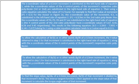
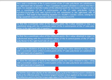
of the crown and they-axis perpendicular to the x-axis (Fig.2d). Thex-axis andy-axis were positive in the right and upwards directions, respectively. The coordinates of the four control points that are needed to obtain the equations of each of the 2 cubic poly-Bezier curves were found using the ruler tool in Photoshop. Figure3gives the cubic Bezier curve formulas and the formulas of their first and second derivatives [15] that were used to find the slope at inflection point and at the 0.5-mm increments from P1to palatal CEJ (Fig.2e, f). Figures4
and5list the procedures done in Microsoft Excel 2013 (Microsoft, Redmond, Washington) to calculate theTorqueAngleValues at the 0.5-mm increments and inflection point.
6. After calculating theTorqueAngleValues of all the 0.5-mm increments and inflection point, the incisor was divided into two incisor parts, a part incisal to the inflection point and a second part cervical to it. Incremental subtractions in each incisor part were done in Excel, where an incremental subtraction was defined as follows: the difference in the
TorqueAngleValue between two successive 0.5 mm increments, where the more incisal increment was always subtracted from the more cervical increment (Table1).
Statistical analysis
The statistical analysis was performed using the tical Package for Social Sciences SPSS (IBM SPSS Statis-tics version 23, Armonk, NY). Intra-observer reliability in tracing the RMCI and in calculating the TorqueAngleValues of their increments was determined using the Dahlberg formula, by randomly selecting 10 incisors and repeating
the tracing and measuring procedures after 1 month. Descriptive statistics for theTorqueAngleValues of the 50 RMCI at the inflection point and at the 0.5-mm increments be-tween [P1] and palatal CEJ were calculated. The fre-quency of positive and negative incremental subtractions in each incisor part of the 50 incisors was found. Since the data did not violate assumption of normality as de-tected by Shapiro-wilk test, one-way ANOVA was done to detect systematic differences between the mean
TorqueAngleValues of the increments and when significant dif-ferences exist Tukey test was used post-hoc. The level of significance was set atp< 0.05 for all statistical tests.
Results
The Dahlberg error for repetitive tracing and measuring procedures was 1.18°.
All 50 incisors studied showed that their 0.5-mm in-crements had a progressive decrease inTorqueAngleValuesfrom P1 to inflection point and an opposite progressive in-crease in TorqueAngleValues from inflection point to the most cervical calculated increment, with the inflection point exhibiting the most negativeTorqueAngleValue. All incremental subtractions in the incisor part cervical to inflection point were positive (478 incremental subtractions), and all incremental subtractions in the incisor part incisal to inflection point were negative (350 incremental subtrac-tions) (Additional file1).
Table 1The torque angle values at the 0.5-mm increments and at the inflection point of the incisor in Figs.1and2are shown in this table. As the palatal CEJ of this incisor is located at thex coordinate point 7.70, the most cervical 0.5-mm increment is [P1+ 7.50]. Incremental subtractions were calculated for the
successive 0.5-mm increments in the incisor part incisal to the inflection point and in the incisor part cervical to the inflection point. An incisor part containing anXnumber of 0.5-mm increments contains a number equal toX−1 of incremental subtractions. Note the progressive decrease in torque angle values of the increments from P1to inflection point and the
opposite progressive increase in the torque angle values of the increments from inflection point to the most cervical calculated increment. An incremental subtraction had a negative value in the incisor part incisal to inflection point and a positive value in the incisor part cervical to it. The inflection point had the most negative torque angle value on PSC
0.5 mm increment Torque angle value Incremental subtraction Number of incremental subtractions Incisor part incisal to inflection point
[P1] 3.26 6
[P1+ 0.50] −0.10 −3.36
[P1+ 1.00] −4.61 −4.51
[P1+ 1.50] −10.85 −6.24
[P1+ 2.00] −19.53 −8.68
[P1+ 2.50] −30.86 −11.33
[P1+ 3.00] −42.21 −11.35
Inflection point [P1+
3.46]
−46.67
Incisor part cervical to inflection point
[P1+ 3.50] −46.63 8
[P1+ 4.00] −41.54 5.09
[P1+ 4.50] −32.68 8.86
[P1+ 5.00] −24.37 8.31
[P1+ 5.50] −17.71 6.66
[P1+ 6.00] −9.24 8.47
[P1+ 6.50] 4.02 13.26
[P1+ 7.00] 21.41 17.39
[P1+ 7.50] 40.84 19.43
Table 2Descriptive statistics of the torque angle values of the PSC of the 50 incisors from [P1] to [P1+ 11] and at the
inflection point. Descriptive statistics of the inflection point location on the PSC of the 50 studied incisors is also shown in this table. N stands for frequency of recorded site and SD for standard deviation
Site N Minimum Maximum Range Mean SD [P1] 50 −3.30 28.62 31.92 9.15 7.90
[P1+ 0.5] 50 −7.62 19.25 26.87 4.95 6.32
[P1+ 1] 50 −9.63 11.66 21.28 0.04 5.40
[P1+ 1.5] 50 −18.38 3.42 21.80 −6.10 5.38
[P1+ 2] 50 −32.14 −2.59 29.55 −14.07 6.70
[P1+ 2.5] 50 −44.96 −7.59 37.37 −24.44 9.40
[P1+ 3] 50 −48.39 −11.80 36.59 −31.88 9.30
[P1+ 3.5] 50 −60.77 −16.91 43.86 −36.34 8.79
[P1+ 4] 50 −52.64 −20.16 32.48 −35.84 6.61
[P1+ 4.5] 50 −45.96 −18.24 27.73 −33.31 6.22
[P1+ 5] 50 −43.15 −15.51 27.64 −29.75 6.21
[P1+ 5.5] 50 −50.27 −9.85 40.42 −26.04 7.47
[P1+ 6] 50 −35.48 6.28 41.77 −20.62 8.87
[P1+ 6.5] 50 −31.96 7.64 39.60 −14.00 9.84
[P1+ 7] 50 −27.82 21.41 49.23 −7.33 11.73
[P1+ 7.5] 50 −20.81 40.84 61.65 0.10 13.77
[P1+ 8] 45 −14.02 48.09 62.11 9.18 15.83
[P1+ 8.5] 34 −9.88 50.10 59.98 13.32 14.86
[P1+ 9] 25 −5.31 46.92 52.24 16.69 12.74
[P1+ 9.5] 12 −1.69 37.92 39.61 18.09 11.92
[P1+ 10] 4 4.91 34.30 29.39 20.77 12.07
[P1+ 10.5] 3 14.50 32.31 17.81 24.63 9.16
[P1+ 11] 1 32.92 32.92 0.00 32.92 –
Inflection point
50 −70.84 −22.71 48.13 −45.82 9.98 Inflection
point location –
[P1+ 2.03] [P1+ 6.17] 4.14 [P1+ 3.73] 0.94
Table 3One-way ANOVA test shows a highly significant difference (p< 0.0001) between the torque angle values of the increments Sum of squares df Mean square F Significance Between groups 270,831.54 22 12,310.52 137.60 < 0.0001 Within
groups
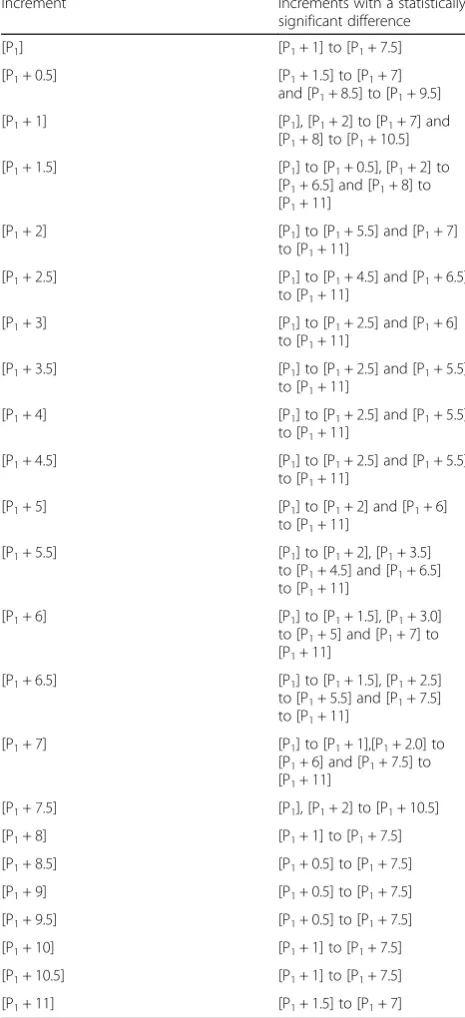
The one-way ANOVA test showed a highly statistically significant difference between the increments, F(22,885) = 137.60, p< 0.0001 (Table 3). The results of the post-hoc Tukey test were mostly significant and are pre-sented in Table4.
Discussion
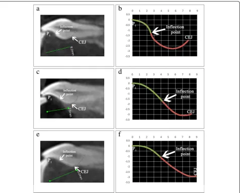
The inflection point of PSC of maxillary central incisor has utmost importance in understanding the directional change in torque which will occur upon a 0.5-mm shift in a vertical bracket position. As incremental subtrac-tions were always positive cervical to inflection point and negative incisal to it, the following can be derived: Cervically oriented shifts or errors in vertical bracket position in an RMCI cause crown labial/root palatal torque changes cervical to inflection point (Fig. 6) and crown palatal/root labial torque changes incisal to it, while incisally oriented shifts cause movements oppos-ite to the mentioned ones cervical and incisal to inflec-tion point, respectively. Furthermore, the more cervical a bracket is placed on the incisor part cervical to inflec-tion point, the more is the potential of crown labial/ root palatal torque expression. Conversely, the more cervical a bracket is placed on the incisor part incisal to inflection point, the more is the potential of crown pal-atal/root labial torque expression. As the inflection point exhibits the most negative TorqueAngleValue on PSC, it is the site with most crown palatal/root labial torque expression potential. The characteristics of the inflec-tion point meninflec-tioned in the four previous sentences justify its use as a torque reference for lingual bracket positioning on the PSC of the maxillary central incisor. Bracket position on PSC specified as either incisal or cervical to inflection point allows the orthodontist to recognize the inherent characteristics of the bracket site rather than it being specified arbitrary and thus devoid of this recognition.
The vast extent ofTorqueAngleValuesat all the 0.5-mm incre-ments of the 50 RMCI studied (Table2) and the statisti-cally significant differences between the TorqueAngleValues of the increments (Tables3 and4) are a scientific justifica-tion through a mathematical model (cubic Bezier) for the use of customized bracket torque prescription on PSC. The adoption of a pre-established bracket torque prescription is inappropriate for embracing the ex-tremely varying PSC morphology of the maxillary central incisor. The most common maxillary central incisor lin-gual bracket torque prescriptions of 40°, 55°, and 68° are not sufficient to cover the wide spectrum ofTorqueAngleValues at each of the 0.5-mm increments.
This study is in agreement with other studies that re-ported on the wide variability in PSC morphology [1,2, 4]. The PSC form of the incisors in this study varied from slight to moderate to complex S-shaped curvatures (Fig. 7). The aforementioned difference in PSC form justifies the approach in lingual orthodontics to individualize the base of each maxillary central incisor lingual bracket [18]. The wide range in the forms of PSC is responsible for the broad variation in the TorqueAngleValues Table 4Post-hoc Tukey test summarized and presented in the
table below. The left side of the table shows an increment while the right side shows which increments were statistically significant different (p< 0.05) from that increment
Increment Increments with a statistically significant difference [P1] [P1+ 1] to [P1+ 7.5]
[P1+ 0.5] [P1+ 1.5] to [P1+ 7]
and [P1+ 8.5] to [P1+ 9.5]
[P1+ 1] [P1], [P1+ 2] to [P1+ 7] and
[P1+ 8] to [P1+ 10.5]
[P1+ 1.5] [P1] to [P1+ 0.5], [P1+ 2] to
[P1+ 6.5] and [P1+ 8] to
[P1+ 11]
[P1+ 2] [P1] to [P1+ 5.5] and [P1+ 7]
to [P1+ 11]
[P1+ 2.5] [P1] to [P1+ 4.5] and [P1+ 6.5]
to [P1+ 11]
[P1+ 3] [P1] to [P1+ 2.5] and [P1+ 6]
to [P1+ 11]
[P1+ 3.5] [P1] to [P1+ 2.5] and [P1+ 5.5]
to [P1+ 11]
[P1+ 4] [P1] to [P1+ 2.5] and [P1+ 5.5]
to [P1+ 11]
[P1+ 4.5] [P1] to [P1+ 2.5] and [P1+ 5.5]
to [P1+ 11]
[P1+ 5] [P1] to [P1+ 2] and [P1+ 6]
to [P1+ 11]
[P1+ 5.5] [P1] to [P1+ 2], [P1+ 3.5]
to [P1+ 4.5] and [P1+ 6.5]
to [P1+ 11]
[P1+ 6] [P1] to [P1+ 1.5], [P1+ 3.0]
to [P1+ 5] and [P1+ 7] to
[P1+ 11]
[P1+ 6.5] [P1] to [P1+ 1.5], [P1+ 2.5]
to [P1+ 5.5] and [P1+ 7.5]
to [P1+ 11]
[P1+ 7] [P1] to [P1+ 1],[P1+ 2.0] to
[P1+ 6] and [P1+ 7.5] to
[P1+ 11]
[P1+ 7.5] [P1], [P1+ 2] to [P1+ 10.5]
[P1+ 8] [P1+ 1] to [P1+ 7.5]
[P1+ 8.5] [P1+ 0.5] to [P1+ 7.5]
[P1+ 9] [P1+ 0.5] to [P1+ 7.5]
[P1+ 9.5] [P1+ 0.5] to [P1+ 7.5]
[P1+ 10] [P1+ 1] to [P1+ 7.5]
[P1+ 10.5] [P1+ 1] to [P1+ 7.5]
of the 0.5-mm increments. Also contributing to this broad variation ofTorqueAngleValuesis the anatomical location of the 0.5-mm increment being measured. For example, the increments [P1+ 3] and [P1+ 3.5] of the RMCI in Fig. 7b are cervical to the inflection point while in the incisor of Fig. 7d those two increments are incisal to it. The anatomical variation in increment location with re-spect to the inflection point between incisors leads to distinctly differentTorqueAngleValues.
Conclusions
1. The inflection point is the anatomical landmark on PSC where directional change in torque occurs in a maxillary central incisor, as of this it can be used as a torque reference for lingual bracket positioning on PSC.
2. Cervically oriented shifts in vertical bracket position in an RMCI cause crown palatal/root labial torque changes incisal to inflection point and crown labial/ Fig. 6aIncrements [P1+ 3] and [P1+ 3.5] has aTorqueAngleValue equal to−60° and−45°, respectively. The incremental subtraction value
root palatal torque changes cervical to inflection point, while incisally oriented shifts cause opposite movements incisal and cervical to inflection point, respectively.
3. The high-standard deviation of the meanTorqueAngleValues of all the 0.5-mm incremental PSC sites of the 50 studied incisors calls for the fabrication of customized brackets that incorporates individualized torque pre-scriptions appropriate to vertical bracket position.
Additional file
Additional file 1:The torque angle value of each 0.5 mm increment and of each inflection point for each of the 50 RMCI used in this study are found in this additional file. Furthermore, the location of each inflection point of each of the 50 RMCI is disclosed here. Each value for each incremental subtraction in the incisor part incisal to inflection point or in the incisor part cervical to the inflection point for each RMCI is also shown in this additional file. (XLSX 76 kb)
Abbreviations
CBCT:Cone beam computed tomography; PSC: Palatal surface curvature; RMCI: Right maxillary central incisor
Acknowledgements
The authors of this study did not receive an aid or advice from other persons.
Funding
The authors funded the study.
Availability of data and materials
The dataset supporting the conclusions of this article is included within the article and its additional file.
Authors’contributions
Ethics approval and consent to participate
Ethical committee approval was obtained from the university’s ethical board before beginning the study (Pre-approval code: 2016H-0040-D-M-0155).
Consent for publication
Not applicable
Competing interests
The authors declare that they have no competing interests.
Publisher’s Note
Springer Nature remains neutral with regard to jurisdictional claims in published maps and institutional affiliations.
Author details
1Department of Developmental Sciences, Division of Orthodontics, Faculty of
Dentistry, Beirut Arab University (BAU), Beirut Campus, Main Building, 1st Floor, Tareek El Jadida P.O. Box 11-5020 Riad El Solh 11072809, Beirut, Lebanon.2Department of Orthodontics and Dentofacial Orthopedics, Henry M. Goldman School of Dental Medicine, Boston University, Boston, USA.
3
Department of Orthodontics, School of Dental Medicine, Saint Joseph University of Beirut, Beirut, Lebanon.4Department of Oral Rehabilitation
Sciences, Division of Dental Biomaterials, Faculty of Dentistry, Beirut Arab University (BAU), Beirut, Lebanon.
Received: 17 April 2018 Accepted: 24 July 2018
References
1. Kurz C, Swartz ML, Andreiko C. Lingual orthodontics: a status report. Part 2: research and development. J Clin Orthod. 1982;16:735–40.
2. Knösel M, Jung K, Gripp-Rudolph L, Attin T, Attin R, Sadat-Khonsari R, et al. Changes in incisor third-order inclination resulting from vertical variation in lingual bracket placement. Angle Orthod. 2009;79:747–54.
3. Dellinger EL. A scientific assessment of the straight-wire appliance. Am J Orthod. 1978;73:290–9.
4. Bryant RM, Sadowsky PL, Hazelrig JB. Variability in three morphologic features of the permanent maxillary central incisor. Am J Orthod. 1984;86:25–32. 5. Vardimon AD, Lambertz W. Statistical evaluation of torque angles in reference
to straight-wire appliance (SWA) theories. Am J Orthod. 1986;89:56–66. 6. Germane N, Bentley BE, Isaacson RJ. Three biologic variables modifying
faciolingual tooth angulation by straight-wire appliances. Am J Orthod Dentofac Orthop. 1989;96:312–9.
7. Germane N, Bentley B, Isaacson RJ, Revere JH. The morphology of canines in relation to preadjusted appliances. Angle Orthod. 1990;60:49–54. 8. Miethke RR. Third order tooth movements with straight wire appliances.
Influence of vestibular tooth crown morphology in the vertical plane. J Orofac Orthop. 1997;58:186–97.
9. Miethke RR, Melsen B. Effect of variation in tooth morphology and bracket position on first and third order correction with preadjusted appliances. Am J Orthod Dentofac Orthop. 1999;116:329–35.
10. van Loenen M, Degrieck J, De Pauw G, Dermaut L. Anterior tooth morphology and its effect on torque. Eur J Orthod. 2005;27:258–62. 11. Vigorito JW, Moresca R, Dominguez GC, Tortamano A. Influence of the
convexity of the upper central incisor on the torque expression of preadjusted brackets. J Clin Orthod. 2006;40:42–6.
12. Sardarian A, Danaei SM, Shahidi S, Boushehri SG, Geramy A. The effect of vertical bracket positioning on torque and the resultant stress in the periodontal ligament--a finite element study. Prog Orthod. 2014;15:50. 13. Kong W-D, Ke J-Y, Hu X-Q, Zhang W, Li S-S, Feng Y. Applications of
cone-beam computed tomography to assess the effects of labial crown morphologies and collum angles on torque for maxillary anterior teeth. Am J Orthod Dentofac Orthop. 2016;150:789–95.
14. Bronshteĭn IN, editor. Handbook of mathematics. 4th ed. berlin. New York: Springer; 2004.
15. Zhang Z, Zhang X, Zhang H. A sampling method based on curvature analysis of cubic Bézier curve. JCP. 2014;9:595–600.
16. Sederberg TW. Computer aided geometric design. 2012;
17. Andrews LF. The straight-wire appliance, origin, controversy, commentary. J Clin Orthod. 1976;10:99–114.


![Table 2 Descriptive statistics of the torque angle values ofthe PSC of the 50 incisors from [P1] to [P1 + 11] and at theinflection point](https://thumb-us.123doks.com/thumbv2/123dok_us/826793.1580226/7.595.304.538.155.537/table-descriptive-statistics-torque-angle-values-incisors-theinflection.webp)
![Fig. 6 a Increments [P1 + 3] and [P1 + 3.5] has a TorqueAngleValue equal to − 60° and − 45°, respectively](https://thumb-us.123doks.com/thumbv2/123dok_us/826793.1580226/9.595.60.537.87.486/fig-increments-p-p-torqueanglevalue-equal-respectively.webp)