A Joint Beamforming based SDMA Protocol for
IEEE 802.11n Downlink
Cheng Guo, Liqiang Zhao, Hui Zhao
State Key Laboratory of Integrated Service Networks,Xidian University, Xi’an, Shaanxi 710071, China
Whai-En Chen
Dept. of Computer Science & Information Engineering National Ilan University
Taiwan [email protected]
Abstract—To support space division multiple access (SDMA) in the IEEE 802.11n downlink, a joint beamforming based MAC protocol, J-MAC is presented in this paper. An access point (AP) follows J-MAC, which employs multiple array antennas, and user equipments (UEs) follow the IEEE 802.11x standard which employ omni-directional MIMO antennas. J-MAC maintains full compatibility with 802.11x, and UEs do not change any more. In J-MAC, firstly, the AP achieves the weight vector for the array antenna-based beamforming, and updates it periodically. Secondly, before transmitting any data-frame, the AP achieves the weight vector for the MIMO-based beamforming, which should be updated in each transmission. Finally, after getting the joint beamforming, the AP transmits its data-frames to multiple UEs simultaneously. Simulation results show that J-MAC can support the joint beamforming effectively and provide much higher network throughput, lower delay, jitter and packet-loss-rate than DCF does.
Keywords: WLAN,SDMA,Beamforming,Array Antenna, MIMO Precoding
I. INTRODUCTION
Wireless LANs (WLANs) have been widely used for broadband wireless access in the past few years, and will achieve sustained and rapid growth with the acceleration of 4G deployment. To meet the increasing requirement of multimedia application, the demand for higher capacity and better reliability, the emerged IEEE 802.11n standard [1] enhances both physical layer (PHY) and media access control (MAC) layer. At the PHY layer, 802.11n employs the Multiple-Input Multiple-Output (MIMO) technology, and its data rate is up to 600Mbps. Moreover, based on the basic MAC protocol, distributed coordination function (DCF), 802.11n adopts Frame Aggregation named Aggregated MAC-level protocol data unit MPDU) and Aggregated MAC-level service data units (A-MSDU) [2] and enhanced Block Acknowledgement (ACK) to obtain a throughput boost.
Although 802.11n has been designed with MIMO technology in mind, it still only concentrates on point-to-point transmission and does not take into account any MAC scheduling schemes for space division multiple access (SDMA). However, MIMO precoding based SDMA is very promising. [3] provided a Multi-user MIMO based opportunistic MAC protocol to achieve higher throughput performance in wireless
networks. After surveying random access based MAC protocols for MU-MIMO enabled WLANs, [4] challenged to design more effective MU-MIMO MAC protocols. [5] proposed a novel MAC scheme combined with a low-complexity beamforming technique at the Physical layer to achieve simultaneous downlink transmissions to multiple users. [6] focused on beamforming and compressed feedback schemes to improve the throughput for a MIMO system. As the successor of 802.11n, 802.11ac could support MU-MIMO, and provide a very high throughput up to Gbps. Although 802.11ac had been standardized, it has not got so popular as 802.11n in deployment up to now. Hence, it is urgent for 802.11n to support SDMA by employing novel antenna technologies.
SDMA can also be implemented with array antennas (AAs) [7], also known as directional antennas. [8] proposed a modified MAC protocol, D-DCF, to support both array antennas and normal omni-directional antennas simultaneously in one WLAN. [9] presented an enhanced MAC protocol for Downlink SDMA in WLANs where only the Access Point is equipped with multiple antennas.
In this paper, we provide a SDMA protocol for the WLAN downlink based on joint beamforming (BF). APs employ multiple array antennas, which are separated by a distance that exceeds the coherent distance of the channel. So they compose a MIMO system, and we can achieve the MIMO-based BF (MIMO-BF) by the precoding technology. On the other hand, the elements or arrays of each antenna are close to each other to form an array antenna system. And we can achieve the AA-based BF (AA-BF). To the authors’ best knowledge, the joint beamforming based SDMA scheme has never been considered in the literature.
The rest of this paper is organized as follows: joint beamforming is presented in section II. J-MAC is introduced in section III. In section IV, performance analysis is described to analyze the system throughput of J-MAC. In section V, simulation studies are carried out to evaluate the proposed scheme. The concluding remarks are given in Section VI.
II. DESCRIPTION OF JOINT BEAMFORMING
AA-BF can shape the radio beam and direct the majority of signal energy to the destination receiver, thus reducing leakage of signal in undesired directions and causing little interference
QSHINE 2015, August 19-20, Taipei, Taiwan Copyright © 2015 ICST
to other receivers. MIMO-BF can support multi-layer or multiuser transmission to improve the system throughput.
At the beginning, the transmitter works in the omni-directional mode as it does not know both the MIMO-BF and AA-BF matrix (i.e., V and W) corresponding to its receivers. Before calculating the two vital matrixes, the transmitter has to get the relevant channel state information (CSI). Since IEEE 802.11x is a time division duplex (TDD) system, the reciprocity between the uplink and downlink channels can be exploited to achieve the CSI. To implement joint BF (J-BF) in the WLAN downlink, firstly, the AP estimates the CSI of the omni-directional channel in the uplink, and calculates the AA-BF matrix based on the estimated omni-directional CSI. Since then, the AP transmits its packets in the AA-BF mode. Secondly, after implementing AA-BF, the AP estimates the CSI of the AA-BF channel in the uplink, and calculates the MIMO-BF matrix based on the estimated directional CSI. Thus, the J-BF is implemented.
To support the J-MAC protocol for the WLAN downlink, the AP is equipped with multiple array antennas which can perform joint beamforming. For simplicity, all the UEs are equipped with one omni-directional antenna.
III. DESCRIPTION OF J-MAC
By exploiting the joint beamforming scheme, we can achieve the spatial multiplex gain. However, the original MAC protocols in 802.11x have not been designed for SDMA and hence they may erode the benefits of joint beamforming. Hence, it is very important to appropriately design the MAC protocol for WLANs.
To achieve the spatial multiplex gain, the AP requires perfect channel knowledge, e.g., direction of departure (DoD) for AA-BF, and directional CSI for MIMO-BF. According to channel reciprocity in the TDD mode, we can implement the joint beamforming based SDMA protocol in the downlink based on the channel knowledge obtained in the uplink. However, to obtain the channel knowledge of the uplink, the AP has to inform the destination UEs to upload two training sequences for the estimation of DoD and CSI respectively, which may cause a large overhead.
In the indoor scenarios, normally a user is stationary or walks in his room, so it is not necessary for the AP to modify its DoD frequently to track its users. In J-MAC, we shall update the DoD from the AP to its given stations (STAs) periodically. On the other hand, as the AP contends with all the other STAs for the channel, the time interval between its two transmissions may be very large. So we assume that the fading coefficients are constant during a transmission and vary from one transmission to another. In J-MAC, we shall estimate the CSI for MIMO-BF before each transmission. Hence, the proposed J-MAC protocol includes three phases.
A. Array antenna-based Beamforming
At the beginning, the AP works in the omni-directional mode as it does not know both the AA-BF and MIMO-BF matrix (i.e., W and V) corresponding to its STAs.
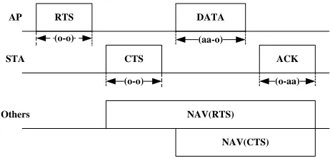
So the AP firstly sends the RTS control-frame to the STA in the omni-directional mode to reserve the channel, as shown in Fig.1. After a SIFS interval, the STA replies the CTS control-frame in the omni-directional mode, which includes a pilot sequence in the PHY header that is preambles. Based on the pilot, AP performs an adaptive algorithm to obtain W, and direct the beam to the STA. After that, AP can transmit its data-frame to this STA at the directed beam. Then the STA sends the ACK control-frame to show that it has received the data-frame from AP successfully. As ACK also includes the pilot, AP can update the W accurately and timely, and keep working in the directional mode. Then, AP can achieve AA-BF with other STAs in the same way.
RTS
CTS (o-o)
DATA (aa-o)
ACK
NAV(RTS) AP
STA
Others
(o-aa)
NAV(CTS) (o-o)
Fig. 1 Array antenna based beamforming (AA-BF)
In Figs1-2, (aa-o) represents the transmitter operating in the directional mode based on AA-BF and the receiver operating in the omni-directional mode; (j-o) represents the transmitter operating in the directional mode based on J-BF and the receiver operating in the omni-directional mode; (o-aa) 、(o-j) and (o-o) are similar to (aa-o). Discussions of the beamforming algorithms are beyond the scope of this paper. In this paper, we assume that desired beamforming algorithms have been implemented at each array antenna to perform the movement tracking and beamforming tasks.
B. MIMO-based Beamforming
Obviously, after implementing AA-BF, the channel has been changed, which is not the initial omni-directional channel. So we have to estimate the CSI after AA-BF again, which will be used for MIMO-BF. After implementing both AA-BF and MIMO-BF, i.e., J-BF, the AP will transmit its packets to multiple STAs simultaneously.
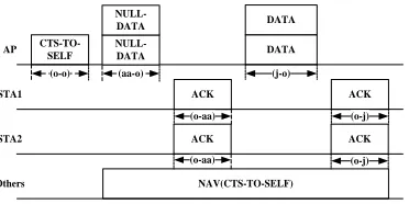
Firstly, in order to reserve the channel for the following SDMA transmission, the AP transmits a CTS-TO-SELF control-frame in the omni-directional mode. The duration/ID field at the preamble of this frame indicates the time that the channel will be occupied. All the STAs adjust their network allocation vectors (NAVs) when their current NAV values are smaller than the duration/ID value of the received control-frame.
After receiving the NULL-DATA frame, both STAs transmit an ACK control-frame as a reply. Based on the achieved AA-BF, the AP can receive the two ACK frames at the same slot.
After receiving the ACK frames, the AP can estimate the directional CSI, and calculate the MIMO-BF matrix V by means of MMSE.
Up to now, both AA-BF and MIMO-BF matrix, i.e., W and
V, have been achieve, so the AP can implement J-BF, and transmit its data-frames to multiple STAs at the same slots.
After receiving the data-frames, the two STAs reply an ACK frame.
CTS-TO-SELF
ACK
(o-aa)
DATA
(j-o)
ACK
NAV(CTS-TO-SELF) AP
STA1
Others
(o-j) (o-o)
NULL-DATA NULL-DATA
ACK
(o-aa)
ACK STA2
(o-j) (aa-o)
DATA
Fig. 2 Joint beamforming based MAC protocol
IV. THROUGHPUTANALYSIS
There are quite a few papers on the analysis of DCF [10-12] and we may look at those analytical models for analyzing the contention procedure of J-MAC. However, to our best knowledge, no one has considered the performance of J-BF. In this section, we shall evaluate the transmission of data-frames in the SDMA mode, as shown in Fig. 2, and do a comparison between J-MAC and DCF.
For a successful data transmission in the downlink, the total time in DCF is:
RTS S
data
T = DIFS + RTS + SIFS + CTS +
SIFS + T + SIFS + ACK
(1)
The total time in J-MAC is:
J MAC S
data
T SIFS CTS to self SIFS Null data
SIFS ACK SIFS T SIFS ACK
(2)
Let:
t DCF
t J
T DIFS RTS SIFS CTS
T SIFS CTS to self SIFS
Null data SIFS ACK
(3)
Assuming the data transmission rate is R. As J-MAC supports AP to communicate with n STAs at the same time, so the data transmission rate in J-MAC is R/n, the throughput can be expressed as:
8 (1 )
8 (1 )
8 DCF
t DCF data
t DCF
F FER
S
T SIFS T SIFS ACK
F FER
F
T SIFS SIFS ACK
R
(4)
8 (1 )
8 (1 )
8
R/ n
8 (1 )
8
( ) / n ( ) / n
J MAC
t J data
t J
t J
n F FER
S
T SIFS T SIFS ACK
n F FER
F
T SIFS SIFS ACK
F FER
F
T SIFS SIFS ACK
R
(5)
Where F is the frame length in bytes, and FER is the Frame Error Rate.
Compared (4) with (5), obviously, we can see that the former is larger than the later. Thus, the throughput in J-MAC is higher than that in DCF.
V. SIMULATION RESULTS
In order to evaluate the performance of our proposed scheme, the following simulations are made. The values of the parameters used to obtain numerical results for simulations are specified in IEEE 802.11n, and some key parameters are given in Table I.
We set a star topology in a rectangular area of 100m×100m with one AP and variable STAs increasing from 5 to 30 in a step of 5. All the STAs are randomly distributed around the AP, and each terminal has a new fixed size packet (8191 bytes) available for transmission immediately after the transmission buffer is empty. For simplicity, the data-frames will be discarded only due to the retransmission time reaches the retry limit.
Four separate array antennas are employed in the AP and each antenna includes twenty arrays. Each STA is configured with one omni-directional antenna. Two array antennas direct their beams to the same STA, and the two independent channels which form a 2×1 MIMO system are used for achieving MIMO-BF together, thus, AP can communicate with two STAs simultaneously.
Table I SIMULATION PARAMETERS Parameters Values Basic channel rate
Channel model AA-BF algorithm MIMO-BF algorithm
A slot time SIFS DIFS
PHY preamble and header time MAC header
6.5Mbps Channel D [13] Eigen-beamforming
SVD 9us 16us0000
034us 43.4us 36 bytes
5 10 15 20 25 30
42 43 44 45 46 47 48 49
Total number of nodes
S
a
tu
ra
ti
o
n
t
h
ro
u
g
h
p
u
t
(M
b
p
s
)
11n-DCF J-MAC
Fig. 3 Saturation throughput
0 5 10 15 20 25 30 35
10-4 10-3 10-2 10-1 100
SNR/dB
F
E
R
QPSK调制
J-MAC-无干扰
J-MAC-有干扰
11n-DCF
Fig. 4 Frame Error Rate
Fig. 3 shows that the saturation throughput in J-MAC is much higher than that in 802.11n, as J-MAC supports the SDMA mode.
In J-MAC, the control overhead is lower than that in DCF, especially in the scenario where there are lots of downlink data services. Moreover, J-MAC supports J-BF, which provides diversity gains and decreases its FER. The FER is shown in Fig.4.
As can be seen from Fig.4, the J-BF has much lower FER than the single MIMO-BF.
5 10 15 20 25 30
0.005 0.01 0.015 0.02 0.025 0.03 0.035 0.04
Total number of nodes
S
a
tu
ra
ti
o
n
d
e
la
y
(
s
)
11n-DCF J-MAC
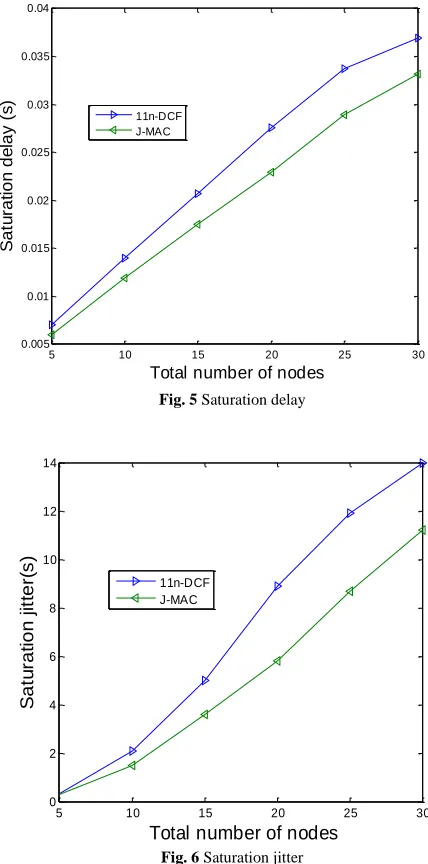
Fig. 5 Saturation delay
5 10 15 20 25 30
0 2 4 6 8 10 12 14
Total number of nodes
S
a
tu
ra
ti
o
n
j
it
te
r(
s
)
11n-DCF J-MAC
Fig. 6 Saturation jitter
Fig.5 shows that the average saturation access delay in J-MAC is lower than that in DCF. Access delay is defined as the duration of time from a packet arriving at the transmission buffer to the packet leaving the buffer.
5 10 15 20 25 30 0
0.05 0.1 0.15 0.2 0.25 0.3 0.35 0.4 0.45 0.5
Total number of nodes
S
a
tu
ra
ti
o
n
p
a
c
k
e
t-lo
s
s
-r
a
te
(%
)
11n-DCF J-MAC
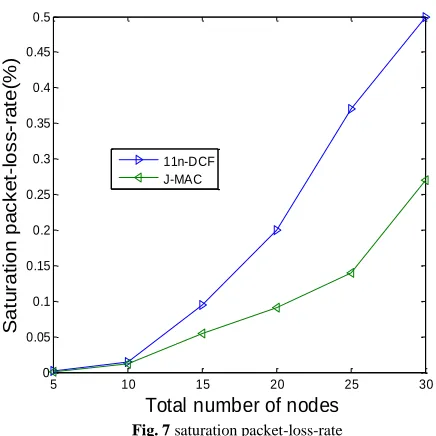
Fig. 7 saturation packet-loss-rate
In general, J-MAC performs better than 802.11n by means of its SDMA mode, and its advantages increase when the AP transmits to more STAs simultaneously in the downlink.
VI. CONCLUSIONS
A joint beamforming based MAC protocol, J-MAC is proposed in this paper to support SDMA in the 802.11n downlink. Based on both AA-BF and MIMO-BF, an AP can achieve spatial diversity gain to reduce its BER and array gain to reduce multiuser interference. Moreover, J-MAC supports AP to obtain omni-directional CSI for AA-BF and directional CSI for MIMO-BF at different stage, where the omni-directional CSI can be automatically updated and the directional CSI needs AP to retrain the MIMO channel to update before each data transmission. Simulation results show that J-MAC supports the SDMA mode effectively in the downlink, and performs much better than 802.11n.
ACKNOWLEDGMENT
This work was supported in part by National Natural Science Foundation of China (No. 61372070), Natural Science Basic Research Plan in Shaanxi Province of China (2015JM6324), Hong Kong, Macao and Taiwan Science &
Technology Cooperation Program of China (2014DFT10320), EU FP7 Project MONICA (PIRSES-GA-2011-295222), and the 111 Project (B08038).
REFERENCES
[1] IEEE Standard for Information technology Telecom- munications and Information exchange between Systems-Local and Metropolitan Area Networks Specific requirements-Part 11: Amendment 5: Enhancements for Higher Throughput, IEEE Std. 802.11nTM-2009.
[2] Y. Kim, E. Monroy, O. Lee, K. Park, and S. Choi, “Adaptive two-level frame aggregation in IEEE 802.11n WLAN,” 18th Asia-Pacific Conference on Communications (APCC), 2012, pp.685-663.
[3] J. Daewon and L. Hyuk, “Opportunistic MAC Protocol for Coordinating Simultaneous Transmissions in Multi-User MIMO Based WLANs,” IEEE Communications Letters, 2011, Vol. 15, No. 8, pp.902-904. [4] R. Liao, B. Bellalta, M. Oliver, and Z. Niu, “MU-MIMO MAC
Protocols for Wireless Local Area Networks: A Survey,” IEEE Communications Surveys & Tutorials, 2014, pp.1.
[5] E. Kartsakli, N. Zorba, L. Alonso, and C. Verikoukis, “A Threshold-Selective Multiuser Downlink MAC Scheme for 802.11n Wireless Networks,” IEEE Transactions on Wireless Communications, Vol.10, No.3, March 2011, pp.857-867.
[6] J. Kim and I. Lee, “802.11 WLAN: history and new enabling MIMO techniques for next generation standards,” IEEE Communications Magazine, 2015, Vol. 53, No. 3, pp.134-140.
[7] A. Alexiou, and M. Haardt, “Smart Antenna Technologies for Future Wireless Systems: Trends and Challenges,” IEEE Communications Magazine, 2004, Vol. 42, No. 9, pp.90-97.
[8] L. Zhao, J. Zhang, and H. Zhang, “Directional distributed co-ordination function – a medium access control protocol to simultaneously support both omni-directional and smart antennas in a same WLAN Cell,” IET Communication, Aug. 2007, Vol.1, pp.765-771.
[9] R. Liao, B. Bellalta, C. Cano, and M. Oliver, “DCF/DSDMA: Enhanced DCF with SDMA Downlink Transmissions for WLANs,” Baltic Congress on Future Internet Communications, 2011, pp.96-102. [10] L. Dai and X. Sun, “A Unified Analysis of IEEE 802.11 DCF Networks:
Stability, Throughput and Delay,” IEEE Transactions on Mobile Computing, 2013, Vol. 12, No. 8, pp.1558–1572.
[11] E. Felemban and E. Ekici, “Single Hop IEEE 802.11 DCF Analysis Revisited: Accurate Modeling of Channel Access Delay and Throughput for Saturated and Unsaturated Traffic Cases,” IEEE Trans. Wireless Comm., 2011, Vol. 10, No. 10, pp.3256–3266.
[12] T. Sugimoto, N. Komuro, H. Sekiya, S. Sakata, and K. Yagyu, "Maximum throughput analysis for RTS/CTS-used IEEE 802.11 DCF in wireless multi-hop networks," International Conference on ICCCE, 201 0, pp.1-6.